O9BARVAEVOBTAVALANCHE BEACON
ASTEELFLASH FRANCE
Click to zoom
Application Details
- Equipment Class
- DCD - Part 15 Low Power Transmitter Below 1705 kHz
- Date of Grant
- Feb 07, 2024
- Application Purpose
- Original Equipment
- Date of Application
- Feb 07, 2024
- Equipment Note
- AVALANCHE BEACON
- Frequency Range
- 0.45700000 - 0.45700000
- Company
- ASTEELFLASH FRANCE
- Country
- France
Documents & Files
Document Text
Text extracted from the exhibit documents filed with the FCC. Open a document above to read the original.
Users Manual
CONNECTING TO THE ARVA APP CONNECTING TO THE ARVA APP Flash the QR code with my camera Download the ARVA app Register my transceiver product Switch on the transceiver by pressing marking to activate Bluetooth Connect my transceiver to the app Configure my transceiver For more information, visit: Profile > My Registered Devices > Settings 2 3 EN Congratulations on purchasing a new ARVA transceiver; this manual contains all the infor- mation you need to use it. This manual is avail- able on our website in the "downloads" section. Register your ARVA device on our website www. arva-equipment.com or on the ARVA app and enjoy an additional 3 years of warranty (regis- tration must be completed within 2 years of the date of purchase). 1.1/ TECHNICAL CHARACTERISTICS 1/ GETTING STARTED INSTRUCTIONS FOR USE 1/ 2/ 3/ 4/ 5/ 6/ 7/ GETTING STARTED TRANSMIT MODE SEARCH MODE PROBING - SHOVELING INTERFERENCE WARRANTY - MAINTENANCE DECLARATION OF CONFORMITY (at the end of the manual) Digital 3-antenna device Search strip width in digital mode: 60 m Active interference management Automatic revert-to-transmit by motion sensor Power supply: 3 AAA/LR03 alkaline batteries Battery life in transmit mode: 350 h with alkaline batteries Storage temperature range: -20 °C to +70 °C Operating temperature range: -20 °C to +45 °C Maximum altitude to function properly: 10 000 m Avalanche beacon / Frequency band : 456.9 - 457.1 kHz Avalanche beacon / Maximum power used : H-Field < 2.23 μA/m @ 10 m Bluetooth 2.4 GHz / Frequency band : 2.400 - 2.4835 GHz Bluetooth 2.4 GHz / Maximum power used : ERP < 100 mW Weight: 193 g (batteries included). 4 EN EVO BT MARKING BUTTON OFF/SEND/SEARCH SELECTOR UNLOCK / EXIT SEND BUTTON ELASTIC ATTACHMENT LANYARD HOLSTER DE PORTAGE 5 EN The information in this manual is for guidance only and is subject to change at any time. The technical features and product specifications may be changed without no- tice for future versions of our devices. No liability is accepted for improper use, failure to follow the operating instructions, unauthorised modifications to the de- vice, continued use despite signs of wear and tear or faults of any kind, or unauthorised or improperly performed repairs. Pictogram inviting users to take end-of-life prod- ucts for recycling Pictogram encouraging users to read instruc- tions and warnings 1.2/ MEANING OF MANUAL / DEVICE PICTOGRAMS Waste disposal for users in private households: this symbol indicates that this product should not be dis- posed of with your other household waste. It is your responsibility to dispose of your waste by taking it to a designated collection point where electrical and electronic devices are recycled properly. Collecting and recycling your waste 1.3/ TRAINING - RESPONSIBILITY Training and practicing so you understand your device com- prehensively is essential for a successful avalanche search. Off-piste skiing/snowboarding and ski touring/splitboarding are risky activities, and wearing a transceiver should never affect your decision making in risky areas. Know when to turn round and go back. 1.4/ STORAGE - BATTERIES You must store your device in a cool, dry place away from direct sunlight. If you plan to store it for a long period, remove the batteries, as the warranty does not cover damage will help conserve natural resources and protect the envi- ronment and people's health. For more information on the nearest recycling centre to your home, contact your local authority, the household waste disposal service or the shop where you purchased the product. 6 EN caused by battery failure (including loss of waterproofing). We recommend that you check your device regularly, includ- ing the operation of the OFF/SEND/SEARCH selector and the condition of the display. Also, ensure there is no trace of cor- rosion in the battery compartment. The EVO BT operates exclusively with three AAA/LR03 alka- line batteries. Do not use rechargeable batteries. The label in the battery compartment is important for customer ser- vice, do not remove it. When you change batteries, change all 3 batteries at the same time. After changing the batteries, make sure that the cover is closed properly. Important for Switzerland: appendix 4.10 of standard SR814.013 applies to batteries. Disposing of a battery in a fire or furnace or mechanically crushing or cutting a battery can cause an explosion. Keeping a battery in a very high-temperature environment can cause an explosion or the escape of flammable liquid or gas. A battery subjected to extremely low air pressure may cause an explosion or leakage of flammable liquid or gas. An explosion may result if the wrong type of battery is used. 1.5/ SETTING UP YOUR DEVICE During the start-up phase, press and hold the marking but- ton. The Bluetooth pictogram appears. You can then connect your transceiver to your smartphone. The ARVA application offers a number of services, including the opportunity to register, set up and maintain your transceiver. 2/ TRANSMIT MODE 2.1/ TURNING ON THE DEVICE The transceiver is off when the rotating selector switch is in the OFF position. To turn on the device, rotate the OFF/ Turn on the transceiver by pressing on marking to activate Bluetooth Connect my transceiver to the app Configure my transceiver 7 EN Once the start-up phase is complete, the device prompts the user to conduct a GROUP CHECK (see paragraph 3.1/ GROUP AND FREQUENCY TEST) and then automatically switches to transmit mode. A blinking arrow in the upper middle of the screen and a characteristic melody confirm that your trans- ceiver is in transmit mode. 2.2/ WEARING THE DEVICE Make sure that the carabiner on the elastic attachment lan- yard is connected to the holster’s waist belt (2 positions, left or right), position the device in the holster with the screen The device then displays the remaining battery life. We advise you to replace the batteries as soon as the battery life indica- tor drops below 50%. …
Text truncated - open the document above for the full version.
Attestation Statements
V02072023 Federal Communications Commission Authorization and Evaluation Division 7435 Oakland Mills Road Columbia, MD 21046 USA Date: 07/26/2023 Ref: Attestation Statement Part 2.911(d)(7) Filing Validity Period: Permanent FCC ID: O9BARVAEVOBT Manufacturer Name ASTEELFLASH FRANCE FRN Applicant 0003784279 Address 43 Chemin du vieux chene 38240 - MEYLAN - France ASTEELFLASH FRANCE certifies that, as of the dates of this application, Americas Compliance Consulting LLC dba iCertifi is our designated U.S. agent for service of process for the above referenced FCC ID. We accept to maintain an agent for no less than one year after the grantee has terminated all marketing and importation or the conclusion of any commission-related proceeding involving the equipment. The US Agent for Service of Process is aware of and agrees to comply with the requirements outlined in the FCC Equipment Authorization Program, Report and Order FCC 22-84, and clause § 2.911. iCertifi accepts, as of the date of the filing of the application, the obligation of the designated U.S. agent for service process for the above: Designated U.S. Agent Information: Name Americas Compliance Consulting, LLC dba iCertifi FCC FRN 0033399411 Address 1001 SW Disk Drive, Suite 250 Bend, Oregon 97702 USA Contact Person Paul Preston Telephone (866) 885-4575 Email [email protected] Sincerely, Benjamin Vanni Americas Compliance Consulting LLC dba iCertifi ASTEELFLASH FRANCE Paul Preston
Cover Letter(s)
Letter of Agency January 17, 2024 To: Federal Communications Commission 7435 Oakland Mills Road Columbia, MD 21046-1609 Timco Engineering, Inc. 13146 NW 86th Drive, Suite 400 Alachua, FL 32615- United States We, the undersigned ASTEELFLASH FRANCE hereby authorizes Majid MOURZAGH, LCIE SUD EST, to act on our behalf in all matters relating to all processes required for FCC certification of our devices. Any and all acts carried out by the above agent on our behalf shall have the same effects as acts of our own. This authorization is valid until: March 31, 2024 If you have any questions regarding this authorization, let us know please. Sincerely, Benjamin Vanni Signature:
Cover Letter(s)
CONFIDENTIALITY REQUEST To: Federal Communications Commission Authorization and Evaluation Division 7435 Oakland Mills Road Columbia, MD 21046-1609 Cc: Timco Engineering, Inc. 13146 NW 86th Drive, Suite 400 Alachua, FL 32615- United States January 17, 2024 Subject: Confidentiality request FCC ID: O9BARVAEVOBT ASTEELFLASH FRANCE requests, pursuant to 47CFR 0.457 and 0.459, post grant confidentiality for portions of the material contained in this application. The following document regarding this submission for FCC ID: O9BARVAEVOBT shall be kept confidential: LONG-TERM CONFIDENTIALITY: 1. Block Diagram description of the equipment (file: Block Diagram - O9BARVAEVOBT.pdf) 2. Schematic Diagram of the equipment (file: Schematic -O9BARVAEVOBT.pdf) The above materials contain trade secrets and proprietary information not customarily released to the public. The public disclosure of these materials may be harmful to the applicant and provide unjustified benefits to its competitors. Permanent Confidentiality: The applicant requests the exhibits listed above as permanently confidential be permanently withheld from public review due to materials that contain trade secrets and proprietary information not customarily released to the public. The applicant understands that disclosure of this application and all accompanying documentation will not be made before the date of the Grant for this application. Sincerely, Responsible party: Benjamin Vanni Title: Project manager Signature:
External Photos
LCIE SUD EST Laboratoire de Moirans Z.I. Centr’Alp 170, Rue de Chatagnon 38430 MOIRANS – France Page 1/2 EXTERNAL PHOTOS OF EQUIPMENT FCCID: O9BARVAEVOBT LCIE SUD EST Laboratoire de Moirans Z.I. Centr’Alp 170, Rue de Chatagnon 38430 MOIRANS – France Page 2/2 Back cover stay not removable
ID Label/Location Info
LCIE SUD EST Laboratoire de Moirans Z.I. Centr’Alp 170, Rue de Chatagnon 38430 MOIRANS - FRANCE Page 1/2 PRODUCT LABELING FCCID: O9BARVAEVOBT LCIE SUD EST Laboratoire de Moirans Z.I. Centr’Alp 170, Rue de Chatagnon 38430 MOIRANS - FRANCE Page 2/2 ID Label Location
Internal Photos
LCIE SUD EST Laboratoire de Moirans Z.I. Centr’Alp 170, Rue de Chatagnon 38430 MOIRANS – France Page 1/4 INTERNAL PHOTOS OF EQUIPMENT FCCID: O9BARVAEVOBT Antenna Y Antenna X LCIE SUD EST Laboratoire de Moirans Z.I. Centr’Alp 170, Rue de Chatagnon 38430 MOIRANS – France Page 2/4 LCIE SUD EST Laboratoire de Moirans Z.I. Centr’Alp 170, Rue de Chatagnon 38430 MOIRANS – France Page 3/4 LCIE SUD EST Laboratoire de Moirans Z.I. Centr’Alp 170, Rue de Chatagnon 38430 MOIRANS – France Page 4/4 BLE Module
Operational Description
LCIE SUD EST Laboratoire de Moirans Z.I. Centr’Alp 170, Rue de Chatagnon 38430 MOIRANS - FRANCE GENERAL INFORMATION FCCID: O9BARVAEVOBT 1.1. Product description LCIE SUD EST Laboratoire de Moirans Z.I. Centr’Alp 170, Rue de Chatagnon 38430 MOIRANS - FRANCE 1.2. Tested System Details LCIE SUD EST Laboratoire de Moirans Z.I. Centr’Alp 170, Rue de Chatagnon 38430 MOIRANS - FRANCE 1.3. Test Methodology Both conducted and radiated testing were performed according to the procedures in ANSI C63.4 or/and ANSI C63.10, FCC Part 15 SubPart 15C. Radiated testing was performed at an antenna to EUT distance of 10 meters. During testing, all equipment’s and cables were moved relative to each other in order to identify the worst case set-up. 1.4. Test facility Tests have been performed: November 22, 2023 to November 24, 2023 This test facility has been fully described in a report and accepted by FCC as compliant with the radiated and AC line conducted test site criteria in ANSI C63.4 or/and ANSI C63.10. This test facility has also been accredited by COFRAC (French accreditation authority for European Union test lab accreditation organization) according to NF EN ISO/IEC 17025, as compliant with test site criteria and competence in 47 CFR Part 15/ANSI C63.4 and EN55032/CISPR32 norms for 89/336/EEC European EMC Directive application. All pertinent data for this test facility remains unchanged.
RF Exposure Info
LCIE SUD EST Laboratoire de Moirans Z.I. Centr’Alp 170, Rue de Chatagnon 38430 MOIRANS – FRANCE RF Exposure Considerations for FCC ID: O9BARVAEVOBT Per FCC KDB 447498 D01 General RF Exposure Guidance v06 The 1-g and 10-g SAR test exclusion thresholds for 100 MHz to 6 GHz are based on source-based time-averaged maximum conducted output power of the RF channel requiring evaluation, adjusted for tune-up tolerance, and the minimum test separation distance required for the exposure conditions. The minimum test separation distance defined in 4.1 f) is determined by the smallest distance from the antenna and radiating structures or outer surface of the device, according to the host form factor, exposure conditions and platform requirements, to any part of the body or extremity of a user or bystander. Minimum test separation distance: 5 mm Step c) For frequencies below 100 MHz, the following may be considered for SAR test exclusion 1) For test separation distances ≤ 50 mm, the power threshold determined by: [(equation in step c) 1) )×( 1 2 )] (푚푊) With 50 mm and 100 MHz (dBm) (mW) Nom 0.457 -49.3 0.000012 0.5 737.06 Exempt from SAR 1925.31 Exempt from SAR Verdict Maximum source-based time averaged conducted output power or EIRP (worst case) including tune-up tolerance Channel Frequency (MHz) Minimum separation distance (mm) Limit for 1-g SAR (mW) Limit for 10-g SAR (mW) Verdict Conclusion: Therefore our device complies with FCC’s RF radiation exposure limits for general population without SAR evaluation.
Test Report
Arva Template: Release October 22 nd , 2022 This document shall not be reproduced, except in full, without the written approval of the LCIE. This document contains results related only to the items tested. It does not imply the conformity of the whole production to the items tested. Unless otherwise specified, the decision of conformity takes into account the uncertainty of measurement. This document doesn’t anticipate any certification decision. The COFRAC accreditation attests the technical capability of the testing laboratory for the only tests covered by the accreditation. If some tests mentioned in this report are carried out outside the framework of COFRAC accreditation, they are indicated by the symbol. Accreditation N°1-1633 Scope available on www.cofrac.fr TEST REPORT N°: 20570161-795244-A Version: 02 Subject Electromagnetic compatibility tests according to the standards: FCC CFR 47 Part 15, Subpart C ANSI C63.4 RSS-210 Issue 10 Issued to ASTEELFLASH FRANCE 43 Chemin du vieux chene 38240 – MEYLAN France Apparatus under test Product AVALANCHE BEACON Trade mark ARVA Manufacturer ASTEELFLASH Model under test EVO BT Serial number RF SIMPLE FCCID O9BARVAEVOBT IC 22008-ARVAEVOBT Conclusion See Test Program chapter §1 Test date November 22, 2023 to November 24, 2023 Test location MOIRANS FCC Test site FR0008 - 918017 ISED Test site FR0008 - 6500A Sample receipt date November 22, 2023 Composition of document 29 pages Document issued on February 2, 2024 Written by : Approved by : Majid MOURZAGH Anthony MERLIN Tests operator Technical manager TEST REPORT N° 20570161-795244-A Version : 02 Page 2/29 PUBLICATION HISTORY Version Date Author Modification 01 January 19 , 2024 Creation of the document 02 February 2, 2024 Majid MOURZAGH Correction FCC Test Site page 1 Add Scan missed on §3.6.5 Each new edition of this test report replaces and cancels the previous edition. The control of the old editions of report is under responsibility of client. TEST REPORT N° 20570161-795244-A Version : 02 Page 3/29 SUMMARY 1. TEST PROGRAM .................................................................................................................................... 4 2. SYSTEM TEST CONFIGURATION ......................................................................................................... 5 3. RADIATED EMISSION DATA (15.209) .................................................................................................... 7 4. FUNDAMENTAL FREQUENCY TOLERANCE (RSS) ........................................................................... 17 5. OCCUPIED BANDWIDTH ..................................................................................................................... 19 6. RECEIVER SPURIOUS EMISSION....................................................................................................... 21 7. UNCERTAINTIES CHART ..................................................................................................................... 29 TEST REPORT N° 20570161-795244-A Version : 02 Page 4/29 1. TEST PROGRAM Standard: - FCC Part 15, Subpart C - ANSI C63.10 (2013) - RSS-210 Issue 10 - RSS-Gen Issue 5 EMISSION TEST LIMITS RESULTS (Comments) Limits for conducted disturbance at mains ports 150kHz-30MHz CFR 47 §15.207 Frequency Quasi-peak value (dBμV) Average value (dBμV) PASS FAIL NA NP 150-500kHz 66 to 56 56 to 46 0.5-5MHz 56 46 5-30MHz 60 50 Radiated emissions 9kHz-30MHz CFR 47 §15.209 (a) CFR 47 §15.225 RSS-Gen §4.9 Measure at 300m 9kHz-490kHz : 67.6dBμV/m /F(kHz) Measure at 30m 490kHz-1.705MHz : 87.6dBμV/m /F(kHz) 1.705MHz-30MHz : 29.5 dBμV/m PASS FAIL NA NP Radiated emissions 30MHz-25GHz* CFR 47 §15.209 (a) CFR 47 §15.225 RSS-Gen §4.9 Highest frequency : (Declaration of provider) Measure at 3m 30MHz-88MHz : 40 dBμV/m 88MHz-216MHz : 43.5 dBμV/m 216MHz-960MHz : 46.0 dBμV/m Above 960MHz : 54.0 dBμV/m PASS FAIL NA NP Fundamental field strength limit CFR 47 §15.225 RSS-210 Operation within the band 456.9-457.1kHz PASS FAIL NA NP Fundamental frequency tolerance CFR 47 §15.225 RSS-210 Operation within the band 456.9-457.1kHz PASS FAIL NA NP Occupied bandwidth RSS-Gen Issue 5 §6.7 No limit PASS FAIL NA NP Receiver Spurious Emission** RSS-Gen Issue 5 §7.3 See RSS-Gen §7.3 30MHz-88MHz : 40 dBμV/m 88MHz-216MHz : 43.5 dBμV/m 216MHz-960MHz : 46.0 dBμV/m Above 960MHz : 54.0 dBμV/m PASS FAIL NA NP *§15.33: The highest internal source of a testing device is defined like more the highest frequency generated or used in the testing device or on which the testing device works or agrees. - If the highest frequency of the internal sources of the testing device is lower than 108 MHz, measurement must be only performed until 1GHz. - If the highest frequency of the internal sources of the testing device ranges between 108 MHz and 500 MHz, measurement must be only performed until 2GHz. - If the highest frequency of the internal sources of the testing device ranges between 500 MHz and 1 GHz, measurement must be only performed until 5GHz. If the highest frequency of the internal sources of the testing device is above 1 GHz, measurement must be only performed until 5 times the highest frequency or 40 GHz, while taking smallest of both. **Testing covered the receive mode, and receiver spurious emissions are considered to be the same as transmitter. TEST REPORT N° 20570161-795244-A Version : 02 Page 5/29 2. SYSTEM TEST CONFIGURATION 2.1. HARDWARE IDENTIFICATION (EUT AND AUXILIARIES): Equipment under test (EUT): EVO BT Serial Number: RF SIMPLE Power supply: During all the tests, EUT is supplied by Vnom: 4.5 VDC For measurement with different voltage, it will be presented in test method. Name Type Rating Reference / Sn Comments Supply1 AC DC Battery 3*1.5 VDC Inputs/outputs - Cable: Access Type Length used (m) Declared <3m Shielded Under test Comments No input or output TEST REPORT N° 20570161-795244-A Version : 02 Page 6/29 Equi…
Text truncated - open the document above for the full version.
Test Setup Photos
LCIE SUD EST Laboratoire de Moirans Z.I. Centr’Alp 170, Rue de Chatagnon 38430 MOIRANS - FRANCE Page 1/2 CONDUCTED AND RADIATED MEASUREMENT PHOTO FCCID: O9BARVAEVOBT 1.1 Radiated emissions LCIE SUD EST Laboratoire de Moirans Z.I. Centr’Alp 170, Rue de Chatagnon 38430 MOIRANS - FRANCE Page 2/2
Contact Information
Applicant
Vanni Benjamin(Project manager)
Test Firm
LCIE Etablissement Sud EstAnthony MERLIN
[email protected]0033 4 76 07 36 35
Technical Specifications
| # | Rule Parts | Frequency Range | Power Output |
|---|---|---|---|
| 1 | 15C | 0.457 MHz - 0.457 MHz | - |
Other Applications from ASTEELFLASH FRANCE
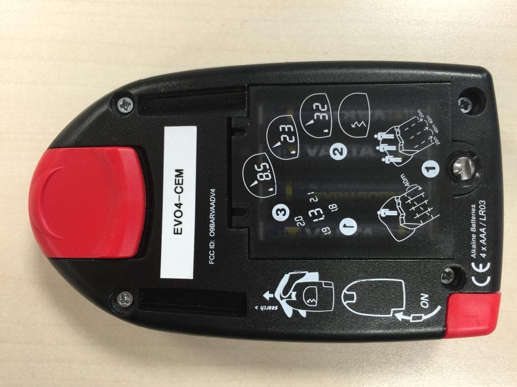
O9BARVAADV4
May 14, 2015Low Power Transmitter Below 1705 kHz
Equipment Class
DCD - Part 15 Low Power Transmitter Below 1705 kHz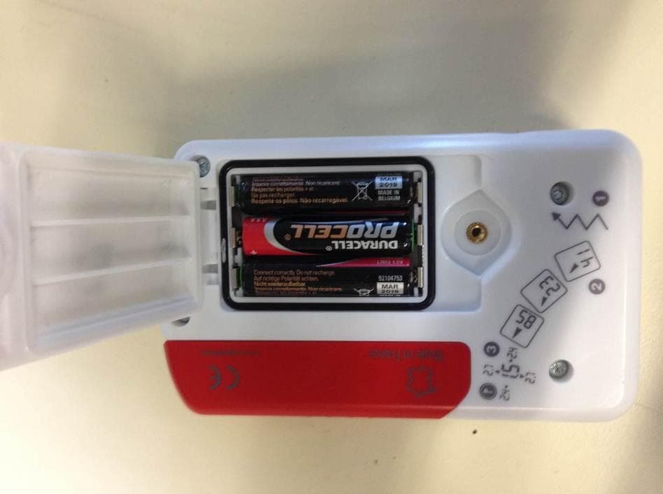
O9BARVANEO
Jul 08, 2014Low Power Transmitter Below 1705 kHz
Equipment Class
DCD - Part 15 Low Power Transmitter Below 1705 kHz
O9BARVAADV
Feb 06, 2005Avalanche Beacon
Equipment Class
DCD - Part 15 Low Power Transmitter Below 1705 kHz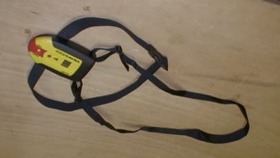
O9BARVA9000
Mar 01, 2001Avalanche transceiver
Equipment Class
DCD - Part 15 Low Power Transmitter Below 1705 kHz