O9BARVAADV4Low Power Transmitter Below 1705 kHz
ASTEELFLASH FRANCE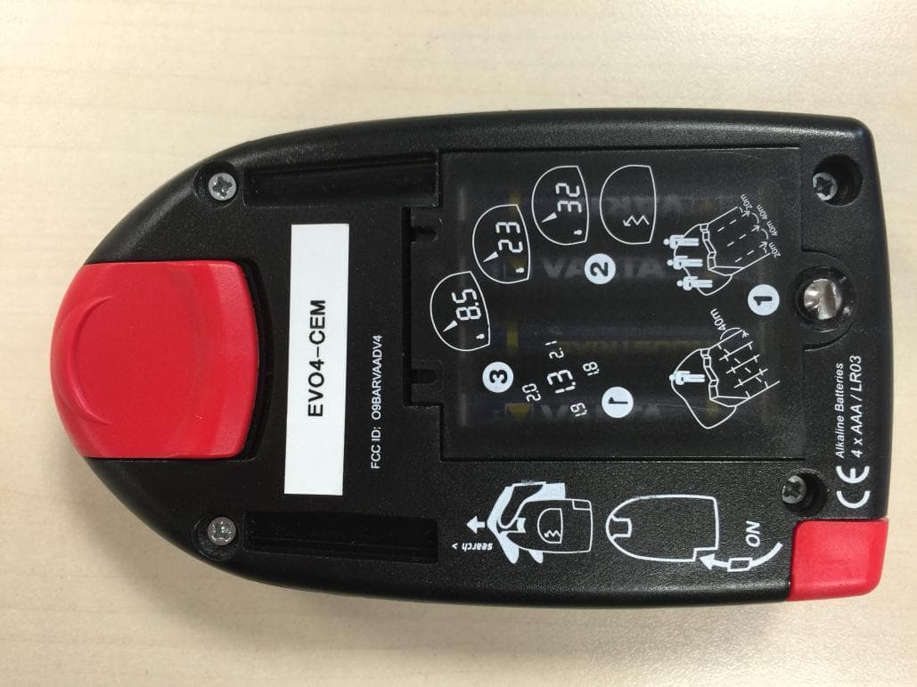
Click to zoom
Application Details
- Equipment Class
- DCD - Part 15 Low Power Transmitter Below 1705 kHz
- Date of Grant
- May 14, 2015
- Application Purpose
- Original Equipment
- Date of Application
- May 14, 2015
- Equipment Note
- Low Power Transmitter Below 1705 kHz
- Frequency Range
- 0.45700000 - 0.45700000
- Company
- ASTEELFLASH FRANCE
- Country
- France
Documents & Files
Document Text
Text extracted from the exhibit documents filed with the FCC. Open a document above to read the original.
Users Manual
Page 1/1 LCIE Laboratoire de Moirans Z.I. Centr’Alp 170, Rue de Chatagnon 38430 MOIRANS-FRANCE USER MANUAL (FCC STATEMENT) FCCID: O9BARVAADV4 This is a copy of the page where the FCC statement is included: CDF15EFR
Users Manual
EVO 4 100% digital USER MANUAL CDF15EFR • 100% digital TECHNICAL FEATURES5-YEAR WARRANTY FOR THIS DEVICE REGISTER YOUR DEVICE ON WWW.ARVA-EQUIPMENT.COM R&TTE Declarations of Conformity Hereby. Name of manufacturer: AsteelFlash France. Adress: 43, rue du Vieux Chêne. Zip Code: 38240. City: Meylan. Country: France. Declares that the ava- lanche beacon. Type designation: EVO4. Trademark: ARVA, is in compliance with the essential requirements and other relevant provisions of directive. 1999/5/EC. The compliance of the device has been evaluated according to the Electromagnetic compatibility standard test: FCC CFR 47 part 15, Subpart C. The complete decla- ration of conformity is available at the address above. Name: TORRES. Fonction: Establishment Development Director. Date: 19/08/2011. Signature: FCC requirements: - FCC ID: O9BARVAADV4 NOTE: This equipment has been tested and found to comply with the limits for a Class B digital de- vice, pursuant to part 15 of the FCC Rules. These limits are designed to provide reasonable protec- tion against harmful interference in a residential installation. This equipment generates uses and can radiate radio frequency energy and, if not installed and used in accordance with the instruc- tion, may cause harmful interference to radio communications. However, there is no guarantee that interference will not occur in a particular in- stallation. If this equipment does cause harmful interference to radio or television reception which can be determined by turning the equipment off and on, the user is encouraged to try to correct Disposal of electronic instruments by users from private house- holds in the European Union. This symbol stamped on the product or its packaging indicates that the product is not allowed to be disposed of with household waste. It is your responsibility to bring your electronics waste to a designated recycling office for proper disposal. Separate disposal and recycling of your waste will contribute to preserving our natural resources and ensure an environmentally-friendly disposal safer for public health. For more information regarding the closest recycling center to your res- idence, contact your local city hall, waste management company, or the store where you purchased the product. The V-shaped conveyor technique allows you to optimize the excavation phase of shoveling. As soon as the person is uncovered, it is important to turn their transceiver off immediately. Search for the victim by probing in concentric spirals progressively away from the minimum distance point detected by your ARVA. Probe perpendicular to the slope. IN SEARCH MODE : Move all metallic and electronic devices at least 50cm away from your transceiver. During an active search, we recommended turning off all devices except : • Analog radio • Headlamp without dimmer • Watch without a radio function • Backup devices in the event of a secondary avalanche Means of communication : We recommend turning off all digital telephones and radios during the active search phase. All calls should be made at least 25m away from the individuals conducting the active search. IN TRANSMIT MODE : Move all metallic and electronic devices at least 20cm away from your transceiver. Certain electronic devices as well as electrical and electromag- netic installations can significantly interfere with transceiver signals. These sources are : • carried: smart phone - analog radio - camera - heart rate monitors - GPS - etc. • permanent: relay towers - power lines / electrical generating equipment - ski lifts, etc. In order to reduce the risk of signal deterioration, we recom- mend that you keep your transceiver as far as possible from sources of electrical and electromagnetic activity. Statistically, shoveling takes at least as much time as the ARVA search. It is important to take a methodic approach to shoveling. This device complies with part 15 of the FCC Rules. Operation is subject to the following two conditions: (1) This device may not cause harmful interference, and (2) this device must accept any interference received, including interference that may cause undesired operation. MULTIPLE BURIAL INDICATOR SHOVELING PROBING INTERFERENCE MARKING FUNCTION • 3 antennas SEARCH/ TRANSMIT BUTTON MARKED VICTIM BUTTON ON/ OFF interference by one or more of the following measures: - Reorient or relocate the receiving antenna. - Increase the separation between the equip- ment and receiver. - Connect the equipment into an outlet on cir- cuit different from that to which the receiver is connected. - Consult the dealer or an experienced radio/ TV technician for help. - Information to user: Changes or modifications not expressly approved by the party responsible for compliance could void the user’s authority to operate the equipment. UNMARKED VICTIM MARKED VICTIM 90 ° 25 cm 25 cm To mark the victim, press on the “marking” button. The device will switch to victim B. When you are less than 3m from the first victim you have the option of marking the location in order to continue searching for another signal. In the illustration example, you can mark victim A. A B • Distance and direction indicator • Marking function for multiple burials • An icon for 1, 2, 3 or more victims • 40m search bandwidth • 220 g • Battery life: 250+ hours • Requires 4 alkaline AAA/ LR06 batteries • Group check 4 OR MORE BURIALS DEVICE USE INSTRUCTIONS INITIAL START-UP GROUP CHECK SWITCHING TO SEARCH MODE SIGNAL SEARCH COARSE SEARCH FINE SEARCH INSERTING BATTERIES AND RECOMMENDATIONS. The ARVA EVO4 only operates with 4 standard Alkaline AAA/ LRO3 batteries. Open the compartment on the back of the device to insert the 4 batteries. The 4 batteries should always be from the same brand and replaced at the same time. BATTERY CHECK Just after turning on your device, it will indicate the battery level. We recommend that you replace the batteries as soon as they drop below 50%. Start searching for a signal based on one of the two diagrams bel…
Text truncated - open the document above for the full version.
External Photos
Page 1/4 LCIE Laboratoire de Moirans Z.I. Centr’Alp 170, Rue de Chatagnon 38430 MOIRANS-FRANCE EXTERNAL PHOTOS OF EQUIPMENT FCCID: O9BARVAADV4 Page 2/4 LCIE Laboratoire de Moirans Z.I. Centr’Alp 170, Rue de Chatagnon 38430 MOIRANS-FRANCE Page 3/4 LCIE Laboratoire de Moirans Z.I. Centr’Alp 170, Rue de Chatagnon 38430 MOIRANS-FRANCE Page 4/4 LCIE Laboratoire de Moirans Z.I. Centr’Alp 170, Rue de Chatagnon 38430 MOIRANS-FRANCE
ID Label/Location Info
Page 1/3 LCIE Laboratoire de Moirans Z.I. Centr’Alp 170, Rue de Chatagnon 38430 MOIRANS-FRANCE PRODUCT LABELING FCCID: O9BARVAADV4 Page 2/3 LCIE Laboratoire de Moirans Z.I. Centr’Alp 170, Rue de Chatagnon 38430 MOIRANS-FRANCE Page 3/3 LCIE Laboratoire de Moirans Z.I. Centr’Alp 170, Rue de Chatagnon 38430 MOIRANS-FRANCE
Internal Photos
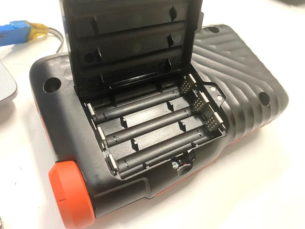
Page 1/2 LCIE Laboratoire de Moirans Z.I. Centr’Alp 170, Rue de Chatagnon 38430 MOIRANS-FRANCE INTERNAL PHOTOS OF EQUIPMENT FCCID: O9BARVAADV4 Page 2/2 LCIE Laboratoire de Moirans Z.I. Centr’Alp 170, Rue de Chatagnon 38430 MOIRANS-FRANCE
Operational Description
LCIE Laboratoire de Moirans Z.I. Centr’Alp 170, Rue de Chatagnon 38430 MOIRANS-FRANCE GENERAL INFORMATION FCCID: O9BARVAADV4 1.1. Product description EVO4 will be upgraded in multiple victims searching with the integration of a central marking button. The digital display clearly indicates whether searching for one, two, or three plus other beacons, and victims can easily be managed in a search with this new button. Also, thanks to its “clip and safe” system the device will always be on when are wearing it. Transceiver: 457 kHz, international frequency 100% digital User friendly Erasing function for multiple victims situations Multiple victims icon 1, 2, 3 and + The 3 inductor listen to the signal ARVA alternately during approximately 10ms. The modulation is a modulation OOK (ton = 70ms ; T = 900ms). 1.2. Tested System Details Equipment Under Test Power supply: During all the tests, EUT is supplied by V nom : 6VDC For measurement with different voltage, it will be presented in test method. Name Type Rating Reference / Sn Comments Supply1 AC DC Battery 6Vdc (4 x LR03 batteries “1.5Vdc”) / INPUTS/OUTPUTS - CABLE Access Type Length used (m) Declared <3m Shielded Under test Comments None AUXILIARY EQUIPMENT USED DURING TEST Type Reference Sn Comments None LCIE Laboratoire de Moirans Z.I. Centr’Alp 170, Rue de Chatagnon 38430 MOIRANS-FRANCE EQUIPMENT INFORMATION RF module: NC Frequency Carrier: [457 kHz Sub-band REC7003: ANNEX 2 – Band A [456.9-457.1kHz] RF mode: Transmitter Transceiver Receiver Standby Antenna type: External: Internal: Antenna gain: NC Equipment location Mobile station Fixed station Extreme temperature range: Category I (General) -20°C to +55°C Category II (Portable) -10°C to +55°C Category III (Indoor) +5°C to +35°C Extreme test source voltage: ±10%: other: From 5.4VDC to 7.8VDC (+30% and – 10%) (Min: 3.6VDC, ask of provider) Equipment designed for continuous operation: NO, emitted each 750ms during 100ms (Declaration of provider) A special configuration of the EUT permits: - Permanent emission of the carrier frequency with modulation - Permanent RX mode Inboard test firmware version: v1.5 1.3. Test Methodology Both conducted and radiated testing were performed according to the procedures in ANSI C63.4-2003, FCC Part 15 Subpart C. Radiated testing was performed at an antenna to EUT distance of 10 meters. During testing, all equipment’s and cables were moved relative to each other in order to identify the worst case set-up. 1.4. Test facility Tests have been performed on from January 27th to 29th , 2015. This test facility has been fully described in a report and accepted by FCC as compliant with the radiated and AC line conducted test site criteria in ANSI C63.4-2003 in a letter dated March 25 th , 2008 (registration number 94821). This test facility has also been accredited by COFRAC (French accreditation authority for European Union test lab accreditation organization) according to NF EN ISO/IEC 17025, accreditation number 1-1633 as compliant with test site criteria and competence in 47 CFR Part 15/ANSI C63.4 and EN55022/CISPR22 norms for 89/336/EEC European EMC Directive application. All pertinent data for this test facility remains unchanged.
Test Report
TEST REPORT N° 813247-R1-E JDE : 132805 Subject : Essais de compatibilité électromagnétique conformément aux normes FCC CFR 47 Part 15, Subpart B et C. Electromagnetic compatibility tests according to the standards FCC CFR 47 Part 15, Subpart B and C ISSUED TO : ASTEEL FLASH DEVELOPPEMENT Immeuble « Le Silène » 43 chemin du Vieux Chêne 38240 MEYLAN - FRANCE Matériel testé / Apparatus under test : Product : DETECTING AVALANCHE VICTIMS Trade mark : ASTEEL FLASH DEVELOPPEMENT Manufacturer : ASTEEL FLASH DEVELOPPEMENT Model : ARVA EVO4 FCCID : O9BARVAADV4 Serial number : EVO4-CEM Test date : From January 27 th to 29 th , 2015 Test location : Moirans Test performed by Jonathan PAUC Composition of document 17 pages Modification of the last version None Document issued on February 25 th , 2015 Written by : Approved by : Jonathan PAUC Anthony MERLIN Tests operator Technical manager This document shall not be reproduced, except in full, without the written approval of the LCIE. This document contains results related only to the item tested. It does not imply the conformity of the whole production to the item tested .Unless otherwise specified; the decision of conformity takes into account the uncertainty of measures. This document does not anticipate any certification decision. RAPPORT D'ESSAI / TEST REPORT N° 813247-R1-E Page : 2 / 17 SUMMARY 1. TEST PROGRAM ............................................................................................................................... 3 2. SYSTEM TEST CONFIGURATION ..................................................................................................... 4 3. RADIATED EMISSION DATA ............................................................................................................. 6 4. ANNEX 1 (GRAPHS) ........................................................................................................................ 11 5. UNCERTAINTIES CHART ................................................................................................................ 17 RAPPORT D'ESSAI / TEST REPORT N° 813247-R1-E Page : 3 / 17 1. TEST PROGRAM Standard: - FCC Part 15, Subpart C - ANSI C63.4 (2003) EMISSION TEST LIMITS RESULTS (Comments) Limits for conducted disturbance at mains ports 150kHz-30MHz Frequency Quasi-peak value (dBμV) Average value (dBμV) NA 150- 500kHz 66 to 56 56 to 46 0.5-5MHz 56 46 5-30MHz 60 50 Radiated emissions 9kHz-30MHz Measure at 300m 9kHz-490kHz : 67.6dBμV/m /F(kHz) Measure at 30m 490kHz-1.705MHz : 87.6dBμV/m /F(kHz) 1.705MHz-30MHz : 29.5 dBμV/m PASS Radiated emissions 30MHz-1GHz* Measure at 3m 30MHz-88MHz : 40 dBμV/m 88MHz-216MHz : 43.5 dBμV/m 216MHz-960MHz : 46.0 dBμV/m Above 960MHz : 54.0 dBμV/m PASS * The highest internal source of a testing device is defined like more the tenth harmonic of highest frequency generated or used in the testing device or on which the testing device works. RAPPORT D'ESSAI / TEST REPORT N° 813247-R1-E Page : 4 / 17 2. SYSTEM TEST CONFIGURATION 2.1. JUSTIFICATION The system was configured for testing in a typical fashion (as a customer would normally use it). 2.2. HARDWARE IDENTIFICATION ARVA EVO4 Sn: EVO4-CEM Equipment Under Test Power supply: During all the tests, EUT is supplied by V nom : 6VDC For measurement with different voltage, it will be presented in test method. Name Type Rating Reference / Sn Comments Supply1 AC DC Battery 6Vdc (4 x LR03 batteries “1.5Vdc”) / INPUTS/OUTPUTS - CABLE Access Type Length used (m) Declared <3m Shielded Under test Comments None AUXILIARY EQUIPMENT USED DURING TEST Type Reference Sn Comments None RAPPORT D'ESSAI / TEST REPORT N° 813247-R1-E Page : 5 / 17 EQUIPMENT INFORMATION Frequency Carrier: 457 kHz RF mode: Transmitter Transceiver Receiver Standby Antenna type: External: Internal: Antenna gain: NC Equipment location Mobile station Fixed station Equipment designed for continuous operation: NO, emitted each 750ms during 100ms (Declaration of provider) 2.3. EUT CONFIGURATION A special configuration of the EUT permits: - Permanent emission of the carrier frequency with modulation - Permanent RX mode Inboard test firmware version: v1.5 2.4. EQUIPMENT MODIFICATIONS None 2.5. SPECIAL ACCESSORIES None RAPPORT D'ESSAI / TEST REPORT N° 813247-R1-E Page : 6 / 17 3. RADIATED EMISSION DATA 3.1. CLIMATIC CONDITIONS Date of test January 27 th , 2014 Test performed by J.PAUC Atmospheric pressure 1005hPa Relative humidity 36% Ambient temperature 22°C 3.2. TEST SETUP The installation of EUT is identical for pre-characterization measurement in a 3 meters semi anechoic chamber and for measures on a 10 meters Open site. Pre-characterisation Measurement RAPPORT D'ESSAI / TEST REPORT N° 813247-R1-E Page : 7 / 17 Radiated emission test setup 3.3. DIVERGENCE, ADDITION OR SUPPRESSION ON THE TEST SPECIFICATION None RAPPORT D'ESSAI / TEST REPORT N° 813247-R1-E Page : 8 / 17 3.1. TEST EQUIPMENT OATS (CHARACTERISATION MEASUREMENT) DESCRIPTION MANUFACTURER MODEL N° LCIE Due Date Antenna Loop ELECTRO-METRICS EM-6879 C2040052 10/15 Cable SUCOFLEX 106G A5329061 02/15 Cable (OATS) - - A5329623 10/15 Radiated emission comb generator BARDET - A3169050 - OATS - - F2000409 09/15 Receiver 20Hz – 8GHz ROHDE & SCHWARZ ESU8 A2642019 01/15* Thermo-hygrometer (PM2) OREGON BAR916HG-G B4206011 04/15 Antenna mast (OATS) LCIE - F2000288 - Turntable / Mast controller (OATS) ETS Lindgren Model 2066 F2000372 - Antenna mast (OATS) ETS Lindgren 2071-2 F2000392 - Turntable (OATS) ETS Lindgren Model 2187 F2000403 - Table MATURO Gmbh - F2000437 - ANECHOIC CHAMBER (PRE-CHARACTERISATION MEASUREMENT) DESCRIPTION MANUFACTURER MODEL N° LCIE Due Date Antenna Loop ELECTRO-METRICS EM-6879 C2040052 10/15 Antenna Bi-Log XWing TESEQ CBL6144 C2040146 11/16 Emission Cable MICRO-COAX 6GHz A5329654 04/15 Receiver 20Hz – 8GHz ROHDE & SCHWARZ ESU8 A2642019 01/15* Emission Cable MICRO-COAX 6GHz A5329655 04/15 Emission Cable MICRO-COAX 6GHz A5329656 04/15 Semi-Anechoic chamber #2 SIEPEL -…
Text truncated - open the document above for the full version.
Test Setup Photos
Page 1/2 LCIE Laboratoire de Moirans Z.I. Centr’Alp 170, Rue de Chatagnon 38430 MOIRANS-FRANCE CONDUCTED AND RADIATED MEASUREMENT PHOTO FCCID: O9BARVAADV4 1.1 Radiated emissions Pre-characterisation Measurement Page 2/2 LCIE Laboratoire de Moirans Z.I. Centr’Alp 170, Rue de Chatagnon 38430 MOIRANS-FRANCE Radiated emission test setup
Contact Information
Applicant
Vanni Benjamin(Project manager)
Test Firm
LCIE Etablissement Sud-EstAnthony Merlin
Technical Specifications
| # | Rule Parts | Frequency Range | Power Output |
|---|---|---|---|
| 1 | 15C | 0.457 MHz - 0.457 MHz | - |
Other Applications from ASTEELFLASH FRANCE
O9BARVAEVOBT
Feb 07, 2024AVALANCHE BEACON
Equipment Class
DCD - Part 15 Low Power Transmitter Below 1705 kHz
O9BARVANEO
Jul 08, 2014Low Power Transmitter Below 1705 kHz
Equipment Class
DCD - Part 15 Low Power Transmitter Below 1705 kHz
O9BARVAADV
Feb 06, 2005Avalanche Beacon
Equipment Class
DCD - Part 15 Low Power Transmitter Below 1705 kHz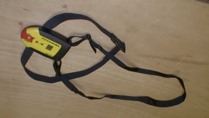
O9BARVA9000
Mar 01, 2001Avalanche transceiver
Equipment Class
DCD - Part 15 Low Power Transmitter Below 1705 kHz