O9C-BJNGAFB0005Unified Wired-WLAN Walljack
Hewlett Packard Enterprise
Click to zoom
Application Details
- Equipment Class
- JBP - Part 15 Class B Computing Device Peripheral
- Date of Grant
- Nov 06, 2014
- Application Purpose
- Original Equipment
- Date of Application
- Nov 04, 2014
- Equipment Note
- Unified Wired-WLAN Walljack
- Company
- Hewlett Packard Enterprise
- Country
- United States
Documents & Files
Document Text
Text extracted from the exhibit documents filed with the FCC. Open a document above to read the original.
Users Manual
The HP 527 is a Wi-Fi Alliance authorized Wi-Fi CERTIFIED 802.11a/b/g/n/ac product. The Wi-Fi CERTIFIED Logo is a certification mark of the Wi-Fi Alliance. 1 Unified Wired-WLAN Walljack (HP 527 Dual Radio 802.11ac) quick start guide This quick start guide shows you how to install and get started using the HP 527 Dual Radio 802.11ac Unified Wired-WLAN Walljack (RMN BJNGA-FB0005) JH048A (AM), JH049A (WW), JH050A (JP), JH051A(IL), JH052A (20 pack AM), JH053A (20 pack WW), hereafter referred to as the HP 527. Hardware overview Back view 1: Pass Through port 2: Uplink port Front view Bottom views 3: GigabitEthernet LAN ports 1 and 2 4: PoE Out GigabitEthernet LAN port 3 5: Pass Through port 12 3 4 5 1 2 2 Package contents The HP 527, mounting bracket, screws, MAC address label, and documentation. Ports Three Gigabit Ethernet ports: Auto-sensing 1000Base-T Ethernet ports with RJ-45 connectors. One Gigabit Ethernet uplink port: Auto-sensing 1000Base-T Ethernet port with RJ-45 connector. One pair of pass-through ports: Work with Cat5 cabling as well as an analog telephone cable. Radio and antennas The HP 527 supports IEEE 802.11a/b/g/n/ac. It has two internal antennas supporting 2x2 MIMO with two spatial streams at a rate of up to 850 Mbps. Reset button The reset button is accessible through a hole on the side panel of the HP 527. To reset the HP 527, insert a paper clip into the reset button hole, and press and quickly release the button. To reset the HP 527 to factory defaults, press and hold the button more than 5 seconds until the status LEDs (Power, Radio, and Uplink) flash, then release. Status LEDs Status LEDs power PoE Out Uplink LAN ports 1, 2, and 3 Radio 3 Power Uplink Radio LAN (1 to 3) PoE Description Off Off Off Off Off The AP has no power. Steady orange Off Off Off Off Power applied. If the power LED remains orange after several minutes, the AP failed to load the software. Green, flashing every 2 seconds (0.5Hz) Off Off Off Off The AP is starting up. Green, flashing every 2 seconds (1Hz) Off Off Off Off The AP is looking for an IP address or building the list of VLANS on which to perform discovery. The power, uplink, and radio LEDs are flashing green in sequence. Off Off The AP has obtained an IP address and is attempting to discover a controller. Steady green The uplink and radio LEDs are flashing green alternately. Off Off The AP has found a controller and is attempting to establish a tunnel with it. The power and uplink LEDs are alternately flashing green (slowly). Off Off Off The AP is performing Ethernet negotiation, and is waiting for the Ethernet link to come up. Steady green Off Any Any Any The uplink interface is not connected or there is no network activity. Steady green Flashing green Any Any Any The uplink interface is active on a valid 1000Mbps link. Steady green Flashing orange Any Any Any The uplink interface is active on a valid 100Mbps link. Steady green Any Off Any Any The radio interfaces are disabled or there is no network activity. Steady green Any Flashing green Any Any Only the 2.4GHz radio interface is transmitting or receiving data. Steady green Any Flashing orange Any Any Only the 5GHz radio interface is transmitting or receiving data. 4 Power Uplink Radio LAN (1 to 3) PoE Description Steady green Any Flashing green and orange alternate ly Any Any Both 2.4GHz and 5GHz radio interfaces are transmitting or receiving data. Steady green Any Any Off Any The uplink interface is disabled or there is no network activity. Steady green Any Any Flashing green Any The LAN interfaces are active on a valid 1000Mbps link. Steady green Any Any Flashing orange Any The LAN interfaces are active on a valid 100Mbps link. Steady green Any Any Any Off No PoE device is connected. Steady green Any Any Any On A PoE device is connected. Powering the HP 527 The HP 527 can be powered by using a local power source, an uninterruptible power supply (UPS), a user-supplied power generator, or a PoE-enabled switch that provides 10/100 Mbps or 10/100/1000 Mbps Ethernet ports. Before you connect power to the AP, verify that the power supply is steady. The HP 527 supports an 802.3af PoE PSE connection to one device on LAN port 3. This feature is dependent on the power source of the HP 527, as follows: Supports 802.3af class 1/2/3 PoE Out when the 803.3at (PoE+) power supply mode is used. Do not support PoE Out when the standard 803.3af power supply mode is used. Important information to read before installing Professional installation is required. For indoor installation only. Before installing or using the AP, consult with a professional installer trained in RF installation and knowledgeable in local regulations including building and wiring codes, safety, channel, power, and license requirements for the intended country. The end user is responsible for ensuring that installation and use comply with local safety and radio regulations. 5 To avoid possible bodily injury or equipment damage, read the following safety recommendations before you install an HP 527. The recommendations do not cover every possible hazardous condition. Install with six inches or more of clearance around the walljack. Keep the chassis clean and dust-free. Make sure the ground is dry and flat and anti-slip measures are in place. Do not place the AP in a moist area and avoid liquid surrounding the AP. Keep the chassis and installation tools away from walkways. Installation 1. Place the mounting bracket, with the UP arrow pointing up, on the electrical outlet box, and then use two of the supplied mounting screws to secure the bracket to the box. The two long mounting screws are for a US electrical box. The two short mounting screws are for an EU electrical outlet box. Long mounting screwShort mounting screw 6 Figure 1 Securing the mounting bracket to an electrical outlet box (EU) Figure 2 Securing the mounting bracket to an electrical outlet box (US) M3.5 × 25 M3.5 × 25 7 2. Connect the network cable…
Text truncated - open the document above for the full version.
External Photos
1 of 4 External Photo (1) EUT Photo (2) EUT Photo (3) EUT Photo (4) EUT Photo (5) EUT Photo (6) EUT Photo (7) EUT Photo (8) EUT Photo
ID Label/Location Info
Label Location JH048A 509*A2 产品名牌 WP388-FN(HP527)-單包 (客戶): HP (材質): FASSON 72826 (上光方式): NO (尺寸): 49*23 mm (公差): +-0.3mm (): BLACK 3:1 Dereck 2014-09-25 C=2.7mm 23mm 49mm 输入 / Input:48V 0.4A(PoE) CMIIT ID:2014AP4254 Complies with IDA Standards DB100427 Regulatory Model:BJNGA-FB0005 FCC ID: O9C-BJNGAFB0005 IC: 2299L-BJNGAFB0005 Hewlett Packard Company MADE IN CHINA
Internal Photos
1 of 6 Internal Photo (1) EUT Photo (2) EUT Photo (3) EUT Photo (4) EUT Photo (5) EUT Photo (6) EUT Photo (7) EUT Photo (8) EUT Photo (9) EUT Photo (10) EUT Photo (11) EUT Photo (12) EUT Photo
Test Report
MRT Technology (Suzhou) Co., Ltd Report No.: 1409RSU02704 Phone: +86-512-66308358 Report Version: V01 Fax: +86-512-66308368 Issue Date: 09-25-2014 Web: www.mrt-cert.com FCC ID: O9C-BJNGAFB0005 Page Number: 1 of 31 FCC ID: O9C-BJNGAFB0005 APPLICANT: Hewlett Packard Company Application Type: Certification Product: Unified Wired-WLAN Walljack Model No.: BJNGA-FB0005, JH048A Brand Name: HP FCC Classification: FCC Class B Digital Device (JBP) FCC Rule Part(s): FCC Part 15 Subpart B Test Procedure(s): ANSI C63.4: 2009 Test Date: Sep. 15 ~ 24, 2014 MEASUREMENT REPORT FCC Part 15B Reviewed By : ( Robin Wu ) Approved By : ( Marlin Chen ) The test results relate only to the samples tested. This equipment has been shown to be capable of compliance with the applicable technical standards as indicated in the measurement report and was tested in accordance with the measurement procedures specified in ANSI C63.4-2009. Test results reported herein relate only to the item(s) tested. The test report shall not be reproduced except in full without the written approval of MRT Technology (Suzhou) Co., Ltd. Report No.: 1409RSU02704 FCC ID: O9C-BJNGAFB0005 Page Number: 2 of 31 Revision History Report No. Version Description Issue Date 1409RSU02704 Rev. 01 Initial report 09-25-2014 Report No.: 1409RSU02704 FCC ID: O9C-BJNGAFB0005 Page Number: 3 of 31 CONTENTS Description Page §2.1033 General Information ......................................................................................................... 4 1. INTRODUCTION ..................................................................................................................... 5 1.1. Scope ........................................................................................................................... 5 1.2. MRT Test Location ....................................................................................................... 5 2. PRODUCT INFORMATION ..................................................................................................... 6 2.1. Equipment Description .................................................................................................. 6 2.2. Description of Available Antennas ................................................................................ 7 2.3. Device Capabilities ....................................................................................................... 7 2.4. Test Configuration ........................................................................................................ 8 2.5. Test Software ............................................................................................................... 9 2.6. EMI Suppression Device(s)/Modifications ..................................................................... 9 2.7. Labeling Requirements ............................................................................................... 10 3. DESCRIPTION OF TEST ....................................................................................................... 11 3.1. Evaluation Procedure .................................................................................................. 11 3.2. AC Line Conducted Emissions .................................................................................... 11 3.3. Radiated Emissions .................................................................................................... 12 4. TEST EQUIPMENT CALIBRATION DATE ............................................................................ 13 5. MEASUREMENT UNCERTAINTY ......................................................................................... 14 6. TEST RESULT ...................................................................................................................... 15 6.1. Summary .................................................................................................................... 15 6.2. Conducted Emission Measurement ............................................................................ 16 6.2.1. Test Limit ................................................................................................................ 16 6.2.2. Test Setup ............................................................................................................... 16 6.2.3. Test Result of Conducted Emissions ....................................................................... 17 6.3. Radiated Emission Measurement ............................................................................... 21 6.3.1. Test Limit ................................................................................................................ 21 6.3.2. Test Setup ............................................................................................................... 21 6.3.3. Test Result of Radiated Emissions .......................................................................... 23 7. CONCLUSION ....................................................................................................................... 31 Report No.: 1409RSU02704 FCC ID: O9C-BJNGAFB0005 Page Number: 4 of 31 §2.1033 General Information Applicant: Hewlett Packard Company Applicant Address: 153 Taylor Street Littleton Massachusetts, United States 01460-1407 Manufacturer: Hewlett Packard Company Manufacturer Address: 153 Taylor Street Littleton Massachusetts, United States 01460-1407 Test Site: MRT Technology (Suzhou) Co., Ltd Test Site Address: D8 Building, Youxin Industrial Park, No.2 Tian’edang Rd., Wuzhong Economic Development Zone, Suzhou, China MRT FCC Registration No.: 809388 Model No.: BJNGA-FB0005, JH048A FCC ID: O9C-BJNGAFB0005 Test Device Serial No.: N/A Production Pre-Production Engineering FCC Classification: FCC Class B Digital Device (JBP) Date(s) of Test: Sep. 15 ~ 24, 2014 Test Report S/N: 1409RSU02704 Test Facility / Accreditations Measurements were performed at MRT Laboratory located in Tian’edang Rd., Suzhou, China. MRT Lab…
Text truncated - open the document above for the full version.
Test Setup Photos
1 of 7 FCC 15B Test Setup Photo Test Mode: Mode 1: Communication (Power by Adapter) Description: Front View of Conducted Emission Test Mode: Mode 1: Communication (Power by Adapter) Description: Front View of Conducted Emission Test Mode: Mode 2: Communication (Power by POE) Description: Back View of Conducted Emission Test Mode: Mode 2: Communication (Power by POE) Description: Back View of Conducted Emission Test Mode: Mode 1: Communication (Power by Adapter) Description: Radiated disturbance Test Setup for 30MHz ~ 1GHz Test Mode: Mode 1: Communication (Power by Adapter) Description: Radiated disturbance Test Setup for 1GHz ~ 18GHz Test Mode: Mode 2: Communication (Power by POE) Description: Radiated disturbance Test Setup for 30MHz ~ 1GHz Test Mode: Mode 2: Communication (Power by POE) Description: Radiated disturbance Test Setup for 1GHz ~ 18GHz FCC Part15C&15E Test Setup Photo Description: Front view of Conducted Emission Test Setup Description: Back view of Conducted Emission Test Setup Description: Radiated Emission Test Setup for 9kHz ~ 30MHz Description: Radiated Emission Test Setup for 30MHz ~ 1GHz Description: Radiated Emission Test Setup for 1GHz ~ 18GHz Description: Radiated Emission Test Setup for 18GHz ~ 40GHz
Contact Information
Applicant
Jim Taylor(Manager, Hardware Support Engineering)
Technical Contact
MRT Technology (Suzhou) Co., LtdRobin Wu
[email protected]86-512-66308358
D8 Building, Youxin Industrial Park, No.2 · Suzhou · China
Non-Technical Contact
MRT Technology (Suzhou) Co., LtdRobin Wu
[email protected]86-512-66308358
Test Firm
MRT Technology (Suzhou) Co., LtdWu Jian
[email protected]86-512-66308358
Technical Specifications
| # | Rule Parts | Frequency Range | Power Output |
|---|---|---|---|
| 1 | 15B | - | - |
Other Applications from Hewlett Packard Enterprise

O9C-BJNGABB0038
Oct 29, 2015HPE MSR954-W 1GbE+SFP LTE (AM) Rtr
Equipment Class
DTS - Digital Transmission System
O9C-BJNGAFB0008
Jul 30, 2015Wireless LAN Access Point
Equipment Class
JBP - Part 15 Class B Computing Device Peripheral
O9C-BJNGAFB0004
Sep 04, 2014Wireless LAN Access Point
Equipment Class
JBP - Part 15 Class B Computing Device Peripheral
O9C-BJNGAFB0003
Jul 02, 2014Unified Wired-WLAN Walljack
Equipment Class
DTS - Digital Transmission System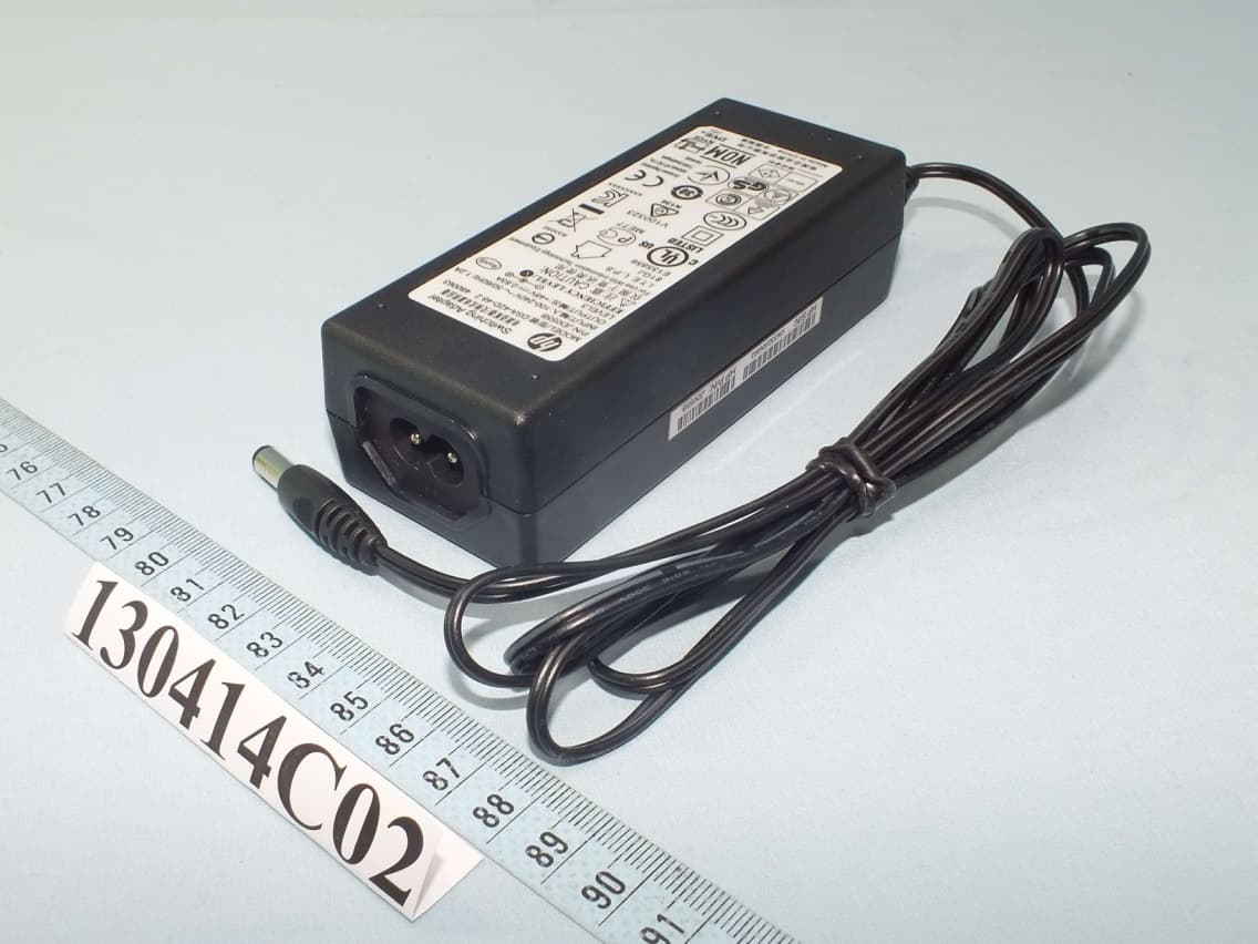
O9C-BJNGAFB0002
Aug 13, 2013HP 425 Wireless 802.11n (AM) AP
Equipment Class
DTS - Digital Transmission System