O9C-DNMA83Wireless mini PCI Card
Hewlett Packard Enterprise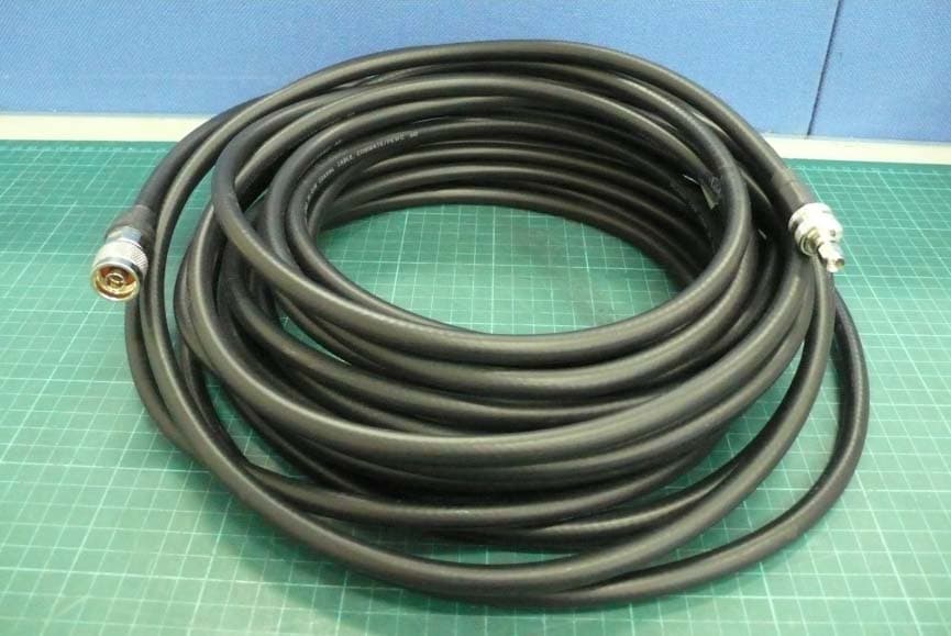
Click to zoom
Application Details
- Equipment Class
- DTS - Digital Transmission System
- Date of Grant
- Dec 23, 2008
- Application Purpose
- Original Equipment
- Date of Application
- Dec 22, 2008
- Equipment Note
- Wireless mini PCI Card
- Frequency Range
- 5745.00000000 - 5825.00000000
- Company
- Hewlett Packard Enterprise
- Country
- United States
Documents & Files
Document Text
Text extracted from the exhibit documents filed with the FCC. Open a document above to read the original.
Users Manual
WLAN mini PCI Card H3C DNMA-83 User Manual Version: 1.0 Nov 2007 1 Copyright Statement No part of this publication may be reproduced, stored in a retrieval system, or transmitted in any form or by any means, whether electronic, mechanical, photocopying, recording or otherwise without the prior writing of the publisher. Windows ™ 98SE/2000/ME/XP are trademarks of Microsoft ® Corp. Pentium is trademark of Intel. All copyright reserved. 2 FCC Statement Warning: Changes or modifications to this unit not expressly approved by the party responsible for compliance could void the user authority to operate the equipment. This equipment has been tested and found to comply with the limits for a Class B digital device, pursuant to Part 15 of the FCC Rules. These limits are designed to provide reasonable protection against harmful interference in a residential installation. This equipment generates, uses and can radiate radio frequency energy and, if not installed and used in accordance with the instructions, may cause harmful interference to radio communications. However, there is no guarantee that interference will not occur in a particular installation. If this equipment does cause harmful interference to radio or television reception, which can be determined by turning the equipment off and on, the user is encouraged to try to correct the interference by one of the following measures: - Reorient or relocate the receiving antenna. - Increase the separation between the equipment and receiver. - Connect the equipment into an outlet on a circuit different from that to which the receiver is connected. - Consult the dealer or an experienced radio/TV technician for help. This device complies with Part 15 of the FCC Rules. Operation is subject to the following two conditions: (1) This device may not cause harmful interference, and (2) this device must accept any interference received, including interference that may cause undesired operation. FCC Caution: Any changes or modifications not expressly approved by the party responsible for compliance could void the user's authority to operate this equipment. IEEE 802.11a operation of this product in the U.S.A. High power radars are allocated as primary users of the 5.25 to 5.35GHz and 5.47 to 5.725GHz bands, do not use these bands. To comply with FCC RF exposure compliance requirements, a separation distance of at least 20 cm must be maintained between the antenna of this device and all persons. This Transmitter must not be co-located or operating in conjunction with any other 3 antenna or transmitter This device is intended only for OEM integrators under the following conditions: The antenna must be installed such that 20 cm is maintained between the antenna and users. For laptop installations, the antenna must be installed to ensure that the proper spacing is maintained in the event the users places the device in their lap during use (i.e. positioning of antennas must be placed in the upper portion of the LCD panel only to ensure 20 cm will be maintained if the user places the device in their lap for use) and The transmitter module may not be co-located with any other transmitter or antenna. As long as the 2 conditions above are met, further transmitter testing will not be required. However, the OEM integrator is still responsible for testing their end-product for any additional compliance requirements required with this module installed (for example, digital device emissions, PC peripheral requirements, etc.). NOTE: In the event that these conditions can not be met (for example certain laptop configurations or co-location with another transmitter), then the FCC authorization is no longer considered valid and the FCC ID can not be used on the final product. In these circumstances, the OEM integrator will be responsible for re-evaluating the end product (including the transmitter) and obtaining a separate FCC authorization. End Product Labeling This transmitter module is authorized only for use in devices where the antenna may be installed such that 20 cm may be maintained between the antenna and users (for example access points, routers, wireless ASDL modems, certain laptop configurations, and similar equipment). The final end product must be labeled in a visible area with the following: "Contains TX FCC ID: O9C-DNMA83 ". RF Exposure Manual Information That Must be Included The users manual for end users must include the following information in a prominent location NOTE: To comply with FCC RF exposure compliance requirements, the antenna used for this transmitter must be installed to provide a separation distance of at least 20 cm 4 from all persons and must not be co-located or operating in conjunction with any other antenna or transmitter." Additional Information That Must be Provided to OEM Integrators The end user should NOT be provided any instructions on how to remove or install the device. Service Center in U.S.A Company Name : 3Com Corporation Company Address: 350 Campus Drive, Marlborough, MA 01752-3064. U.S.A. Service Center in Canada Company Name : 3Com Canada Company Address: 466 Speers Road 3rd Floor Oakville, ON, L6K 3W9 5 Table of Contents 1. INTRODUCTION 6 2. DRIVER/UTILITY INSTALLATION / UNINSTALLATION 7 2.1 INSTALLATION..........................................................................................................7 2.2 ADDITIONAL SETUP PROCESSES............................................................................10 2.3 UNINSTALLATION................................................................................................... 11 3. CONNECTING TO AN EXISTING NETWORK 12 4. CREATING AN AD HOC NEW NETWORK 17 5. MODIFYING A WIRELESS NETWORK 21 5.1 INFRASTRUCTURE MODE AND AD HOC MODE.....................................................21 5.2 MODIFYING A WIRELESS NETWORK.....................................................................22 5.3 DEFAULT SETTINGS WINDOWS XP ZERO-CONFIGURATION................................29…
Text truncated - open the document above for the full version.
Cover Letter(s)
Lettery of Agency "I, an officer of 3Com Corporation do hereby authorize Kevin Chen, who is Chief. Engineer in Intertek Testing Services Taiwan Ltd. to act on our behalf in front of the Federal Communications Commission with respect to all matters relating to certification of equipment under Part 15 and Part 18 of the FCC Rules until further notice." I further certify that no party (as defined in §1.2002(b) of CFR 47, 1992) to this application, including myself, is subject to a denial of federal benefits, that includes FCC benefits, pursuant to Section 5301 of the Anti-Drug Abuse Act of 1988, 21 U.S.C.,853(a). By: Stanley Lin Signature Printed Title: Project Manager Date: 2008-Dec-10
Cover Letter(s)
Attn: Director of Certification Authority to Act as Agent I appoint __Intertek Testing Service Taiwan Ltd._____ to act as our agent in the preparation of this application for equipment certification. I certify that submitted documents properly describe the device or system for which equipment certification is sought. I also certify that each unit manufactured, imported or marketed, as defined in Industry Canada’s regulations will have affixed to it a label identical to that submitted for approval with this application. For instances where our authorized agent signs the application for certification on our behalf, I acknowledge that all responsibility for complying with the terms and conditions for Certification, as specified by American TCB, still resides with _3Com Corporation, 350 Campus Drive Marlborough, MA 01752-3064, United States ___. Dated this 12 day of December , 2008 Agency Agreement Expiration Date: (Typically 8-12 months) By: __________________________ __Stanely Lin_______ (Signature) (Print name) Title: _Project Manager email: [email protected]__ On behalf of: 3Com Corporation (Company Name) Telephone: _+886-2-2176-9088__
Cover Letter(s)
FCC ID:O9C-DNMA83 Date: Dec.17, 2008 Modular Approval Request Letter Dear Sir, There’s an Wireless mini PCI Card that would like to have your authorization as a modular approval. The specific product as below, Wireless mini PCI Card, with its designed features and specified description, meets special requirements for full modular approval on FCC Public Notice DA 00-1407 by cross-reference list below. Company : 3Com Corporation Model Name : Wireless mini PCI Card Model Number : H3C DNMA-83 FCC ID : O9C-DNMA83 Requirement of Public Notice DA00-1407 Reference to H3C DNMA-83 1. The modular transmitter must have its own RF shielding. The module has its own RF shielding. Please see external photo.pdf 2. The modular transmitter must have buffered modulation/data inputs. The modular has buffered data inputs, it is integrated in chip AR9106-AL1A. Please see diagram.pdf 3. The modular transmitter must have its own power supply regulation. All power lines derived from the host device are regulated before energizing other circuits internal to the H3C DNMA-83. Please see circuit.pdf 4. The modular transmitter must comply with the antenna requirements of Section 15.203 and 15.204(c). The H3C DNMA-83 meets the FCC antenna requirements. It has a unique connector. Please see external photo.pdf 5. The modular transmitter must be tested in a stand-alone configuration, i.e., the module must not be inside another device during testing. The H3C DNMA-83 was tested in a stand-alone configuration via a PCMCIA extender. Please see conducted set-up photo.pdf and spurious set-up photo.pdf 6. The modular transmitter must be labeled with its own FCC ID number, and, if the FCC ID is not visible when the module is installed inside another device, then the outside of the device into which the module is installed must also display a label referring to the enclosed module. The label position of H3C DNMA-83 is clearly indicated. Please see the label.pdf 7. The modular transmitter must comply with any specific rule or operating requirements applicable to the transmitter and the manufacturer must provide adequate instructions along with the module to explain any such requirements. A copy of these instructions must be included in the application for equipment authorization. The H3C DNMA-83 is compliant with all applicable FCC rules. Detail instructions are given in the Users Manual. Please see Installation guide.pdf 8. The modular transmitter must comply with any applicable RF exposure requirements. For example, FCC Rules in Sections 2.1091, 2.1093 and specific Sections of Part 15, including 15.319(i), 15.407(f), 15.253(f) and 15.255(g), require that Unlicensed PCS, UNII and millimeter wave devices perform routine environmental evaluation for RF Exposure to demonstrate compliance. In addition, spread spectrum transmitters operating under Section 15.247 are required to address RF Exposure compliance in accordance with Section 15.247(b)(4). The H3C DNMA-83 comply with applicable RF exposure requirements. Please see RF safety evaluation. pdf Yours sincerely, Jimmie Liu Engineer Intertek Testing Service Taiwan Ltd.
Cover Letter(s)
Applicant: Hangzhou H3C Technologies Co., Ltd. FCC ID: O9C-DNMA83 To whom it may concern, Our wireless product (Product name: Wireless mini PCI Card, Model number: H3C DNMA-83) is base on country’s requirement of customer to setup wireless channel. For different country, we have different country code to setup. The country code is fixed and user can’t change it. The user in American can only use channel 36, 40, 44, 48, 149, 153, 157, 161 and 165, 11n- HT20: the same as 11a opened channels and 11n-HT40: 38, 46, 151 and 159. Best regards. Stanely Lin Project Manager
Cover Letter(s)
American Telecommunications Certification Body Inc. 6731 Whittier Ave, McLean, VA 22101 August 26, 2009 TO: Federal Communications Commission RE: Request for placement into audit status for FCC ID: O9C-DNMA83 for supercede of original test report Please supercede the original test reports for NII and DTS due to typo – original test reports have typo in antenna types – information is still compliant. Thank you. Marianne Bosley American TCB Inc. Direct 717-676-3203
Cover Letter(s)
Intertek Testing Services Taiwan Ltd. 5F, No. 423, Ruiguang Rd., Neihu District, Taipei 11492, Taiwan, R.O.C. Telephone: (+886-2) 6602-2888 Facsimile: (+886-2) 6602-2415 www.taiwan.intertek-etlsemko.com Date: August 4, 2009 RE: Supersede request for FCC ID: O9C-DNMA83, grant date: 12/24/2008 To whom it may concern, We need your kind help to supersede the FCC ID: O9C-DNMA83 original test report with new one as attachment, since we found the antenna information is incorrected because of typo. The EUT with antennas was performed correctly and test result was fully complied with FCC regulation, but we were misunderstanding with client for the antenna description. The antenna’s model no. which performed with EUT is C5060-510002-A (gain: [email protected], 3dBi@5GHz), but we listed 3CWE590 (gain: [email protected], 2dBi@5GHz) to the test report. We’ve corrected antenna relative information in Page 5, Page 7 and Page 8 of DTS report (report no.: TS08100102-EME) and page 5 of UNII report (report no.: TS08100102-EME). Please help supersede the exhibit of test reports. I’m so sorry for causing you any inconvenience and thank you so much for your help. Should you have any question, please don’t hesitate to contact with me. Best regards. Lynn Yang Sr. Specialist Tel: 886-3-519-1411 ext:303 Intertek 11, Ln. 275, Ko Nan 1st. Shiang-Shan District, Hsinchu 300 Taiwan, R.O.C. Fax: 886-3-519-1410 e-mail: [email protected] www.taiwan.intertek-etlsemko.com
External Photos
Photo 1: External photo of EUT H3C DNMA-83 Photo 2: External photo of EUT H3C DNMA-83 Photo3: External photo of EUT Antenna 1 (Model: 3CWE590) H3C DNMA-83 Photo 4: External photo of EUT Antenna 2 (Model: 3CWE591) H3C DNMA-83 Photo 5: External photo of EUT Antenna 3 (Model: 3CWE596) H3C DNMA-83 Photo 6: External photo of EUT Antenna 3 (Model: 3CWE596) H3C DNMA-83 Photo 7: External photo of EUT Antenna 4 (Model: 3CWE598) H3C DNMA-83 Photo 8: External photo of EUT Antenna 4 (Model: 3CWE598) H3C DNMA-83 Photo 9: External photo of EUT Antenna cable (Model: 3CWE580) H3C DNMA-83 Photo 10: External photo of EUT Antenna cable (Model: 3CWE581) H3C DNMA-83 Photo 11: External photo of EUT Antenna cable (Model: 3CWE582) H3C DNMA-83
ID Label/Location Info
FCC ID Label Location
Internal Photos
Photo 1: Internal photo of EUT Photo 2: Internal photo of EUT Photo 3: Internal photo of EUT Antenna Connecter (Model: 3CWE591) Photo 4: Internal photo of EUT Antenna Connecter (Model: 3CWE596) Photo 5: Internal photo of EUT Antenna Connecter (Model: 3CWE598)
Test Report
FCC ID. : O9C-DNMA83 Report No.: TS08100102-EME Page 209 of 303 8. Radiated Spurious Emission Name of Test Radiated Spurious Emission Base Standard FCC 15.247(d), 15.209, 15.205 Test Result: Complies Measurement Data: See Tables below Method of Measurement: Reference FCC document: KDB558074, ANSI C63.4 The frequency range from 30 MHz to 1000 MHz using Bilog Antenna. The frequency range over 1 GHz using Horn Antenna. Radiated emissions were invested cover the frequency range from 30 MHz to 1000 MHz using a receiver RBW of 120 kHz record QP reading, and the frequency over 1 GHz using a spectrum analyzer RBW of 1 MHz and 10 Hz VBW record Average reading. (15.209 paragraph), the Peak reading (1 MHz RBW/VBW) recorded also on the report. The EUT for testing is arranged on a wooden turntable. If some peripherals apply to the EUT, the peripherals will be connected to EUT and the whole system. During the test, all cables were arranged to produce worst-case emissions. The signal is maximized through rotation. The height of antenna and polarization is changing constantly for exploring for maximum signal level. The height of antenna can be up to 4 meters and down to 1 meter. The measurement for radiated emission will be done at the distance of three meters unless the signal level is too low to measure at that distance. In the case of the reading under noise floor, a pre-amplifier is used and/or the test is conducted at a closer distance. And then all readings are extrapolated back to the equivalent 3 meters reading using inverse scaling with distance. The EUT configuration please refer to the “Spurious set-up photo.pdf”. FCC ID. : O9C-DNMA83 Report No.: TS08100102-EME Page 210 of 303 Test Diagram: Emission Limit: The spurious Emission shall test through the 10th harmonic. In addition, radiated emissions which fall in the restricted bands, as defined in §15.205(a), must also comply with the radiated emission limits specified in §15.209(a). Frequency (MHz) Limits (dBμV/m@ 3 meter) 30-88 40 88-216 43.5 216-960 46 Above 960 54 Remark: 1. In the above table, the tighter limit applies at the band edges. 2. Distance refers to the distance in meters between the measuring instrument antenna and the closed point of any part of the device or system Note: (1) The EUT was tested while in a continuous transmit mode and the worst case data rates are 1 Mbps for 802.11b, 6 Mbps for 802.11a/ 11g, 6.5Mbps for 802.11n HT20 and 13.5Mbps for 802.11n HT40. The EUT was tuned to a low, middle and high channel. (2) The EUT operating at 2.4 GHz ISM band. Frequency Range scanned from 30 MHz to 25 GHz. Horn or Bilog Antenna RF Test Receiver Ground Plane Antenna To w e r □ 3 meter 1-4 meter 0.8 meter EUT& Peripheral HPF and Pre-Amp. (if necessary) FCC ID. : O9C-DNMA83 Report No.: TS08100102-EME Page 211 of 303 Measurement results: frequencies equal to or less than 1 GHz The test was performed on EUT under 802.11b, 802.11g, 802.11a, 802.11n HT20 and 802.11n HT40 continuously transmitting mode. The worst case occurred at 802.11b Tx channel 1. EUT : H3C DNMA-83 Worst Case : 802.11b Tx at channel 1 with Mode 1 Antenna Freq. ReceiverCorr. ReadingCorrectedLimit Margin Polariz. Factor Level @ 3 m (V/H) (MHz) Detector(dB/m)(dBuV)(dBuV/m)(dBuV/m) (dB) V 76.560 QP 10.3917.9028.29 40.00 -11.71 V 219.150 QP 11.6523.3334.98 46.00 -11.02 V 249.220 QP 12.2218.8631.07 46.00 -14.93 V 316.150 QP 14.1011.8625.96 46.00 -20.04 V 450.010 QP 17.689.68 27.36 46.00 -18.64 V 483.960 QP 18.438.93 27.35 46.00 -18.65 H 81.410 QP 9.45 27.8637.30 40.00 -2.70 H 137.670 QP 12.3227.5339.85 43.50 -3.65 H 249.220 QP 12.3626.5938.95 46.00 -7.05 H 319.060 QP 14.3216.8131.12 46.00 -14.88 H 814.730 QP 23.628.58 32.20 46.00 -13.80 H 991.270 QP 25.838.88 34.70 54.00 -19.30 Remark: 1. Corr. Factor = Antenna Factor + Cable Loss 2. Corrected Level = Reading + Corr. Factor FCC ID. : O9C-DNMA83 Report No.: TS08100102-EME Page 212 of 303 EUT : H3C DNMA-83 Worst Case : 802.11b Tx at channel 1 with Mode 2 Antenna Freq. ReceiverCorr. ReadingCorrectedLimit Margin Polariz. Factor Level @ 3 m (V/H) (MHz) Detector(dB/m)(dBuV)(dBuV/m)(dBuV/m) (dB) V 183.260 QP 13.1023.9036.99 43.50 -6.51 V 249.220 QP 12.2220.4532.66 46.00 -13.34 V 351.070 QP 15.0616.5531.61 46.00 -14.39 V 596.480 QP 20.7112.6133.32 46.00 -12.68 V 681.840 QP 22.337.03 29.35 46.00 -16.65 V 862.260 QP 23.7012.0135.71 46.00 -10.29 H 183.260 QP 12.0827.1539.23 43.50 -4.27 H 249.220 QP 12.3626.6839.04 46.00 -6.96 H 480.080 QP 18.6411.4530.09 46.00 -15.91 H 596.480 QP 20.8413.5334.36 46.00 -11.64 H 749.740 QP 22.9510.7033.65 46.00 -12.35 H 949.560 QP 25.338.38 33.71 46.00 -12.29 Remark: 1. Corr. Factor = Antenna Factor + Cable Loss 2. Corrected Level = Reading + Corr. Factor FCC ID. : O9C-DNMA83 Report No.: TS08100102-EME Page 213 of 303 EUT : H3C DNMA-83 Worst Case : 802.11b Tx at channel 1 with Mode 5 Antenna Freq. ReceiverCorr. ReadingCorrectedLimit Margin Polariz. Factor Level @ 3 m (V/H) (MHz) Detector(dB/m)(dBuV)(dBuV/m)(dBuV/m) (dB) V 50.370 QP 12.9016.5829.47 40.00 -10.53 V 141.550 QP 14.2719.5233.79 43.50 -9.71 V 249.220 QP 12.2218.5830.79 46.00 -15.21 V 338.460 QP 14.9812.4227.40 46.00 -18.60 V 749.740 QP 22.7411.7434.48 46.00 -11.52 V 862.260 QP 23.7010.6534.35 46.00 -11.65 H 125.060 QP 11.6218.8730.48 43.50 -13.02 H 249.220 QP 12.3622.7435.10 46.00 -10.90 H 320.030 QP 14.3211.7026.01 46.00 -19.99 H 374.350 QP 15.4810.5826.05 46.00 -19.95 H 720.640 QP 22.448.22 30.66 46.00 -15.34 H 749.740 QP 22.9512.8435.79 46.00 -10.21 Remark: 1. Corr. Factor = Antenna Factor + Cable Loss 2. Corrected Level = Reading + Corr. Factor FCC ID. : O9C-DNMA83 Report No.: TS08100102-EME Page 214 of 303 EUT : H3C DNMA-83 Worst Case : 802.11b Tx at channel 1 with Mode 8 Antenna Freq. ReceiverCorr. ReadingCorrectedLimit Margin Polariz. Factor Level @ 3 m (V/H) (MHz) Detector(dB/m)(dBuV)(dBuV/m)(dBuV/m) (dB) V 44.550 QP 12.3820.7533.12 40.00 -6.88 V 143.490 QP 14.2714.6428.91 43.50 -14.59 V 224.970 QP 12.0816.5828.66 46.00 -17.34 V 239.520…
Text truncated - open the document above for the full version.
Test Setup Photos
Photo 1: Conducted Emission Test Set-up photo H3C DNMA-83 Photo 2: Conducted Emission Test Set-up photo H3C DNMA-83 Photo 1: Radiated Emission Test set-up photo Antenna 1 (Model: 3CWE590) H3C DNMA-83 Photo 2: Radiated Emission Test set-up photo Antenna 1 (Model: 3CWE590) H3C DNMA-83 Photo 3: Radiated Emission Test set-up photo Antenna 2 (Model: 3CWE591) H3C DNMA-83 Photo 4: Radiated Emission Test set-up photo Antenna 2 (Model: 3CWE591) H3C DNMA-83 Photo 5: Radiated Emission Test set-up photo Antenna 3 (Model: 3CWE596) H3C DNMA-83 Photo 6: Radiated Emission Test set-up photo Antenna 3 (Model: 3CWE596) H3C DNMA-83 Photo 7: Radiated Emission Test set-up photo Antenna 4 (Model: 3CWE598) H3C DNMA-83 Photo 8: Radiated Emission Test set-up photo Antenna 4 (Model: 3CWE598) H3C DNMA-83
Contact Information
Applicant
Jim Taylor(Manager, Hardware Support Engineering)
Technical Contact
Intertek Testing ServicesKevin Chen
[email protected]886-3-519-1411
No. 11 Ko-Tze-Nan Chia-Tung Li · Hsinchu · Taiwan
Test Firm
Intertek Testing Services Taiwan Ltd.Lily Shih
Technical Specifications
| # | Rule Parts | Frequency Range | Power Output |
|---|---|---|---|
| 2 | 15C | 5.75 GHz - 5.83 GHz | 660.00 mW |
Other Applications from Hewlett Packard Enterprise

O9C-BJNGABB0038
Oct 29, 2015HPE MSR954-W 1GbE+SFP LTE (AM) Rtr
Equipment Class
DTS - Digital Transmission System
O9C-BJNGAFB0008
Jul 30, 2015Wireless LAN Access Point
Equipment Class
JBP - Part 15 Class B Computing Device Peripheral
O9C-BJNGAFB0005
Nov 06, 2014Unified Wired-WLAN Walljack
Equipment Class
JBP - Part 15 Class B Computing Device Peripheral
O9C-BJNGAFB0004
Sep 04, 2014Wireless LAN Access Point
Equipment Class
JBP - Part 15 Class B Computing Device Peripheral
O9C-BJNGAFB0003
Jul 02, 2014Unified Wired-WLAN Walljack
Equipment Class
DTS - Digital Transmission System