O9C-SL1021SL-1021
Hewlett Packard Enterprise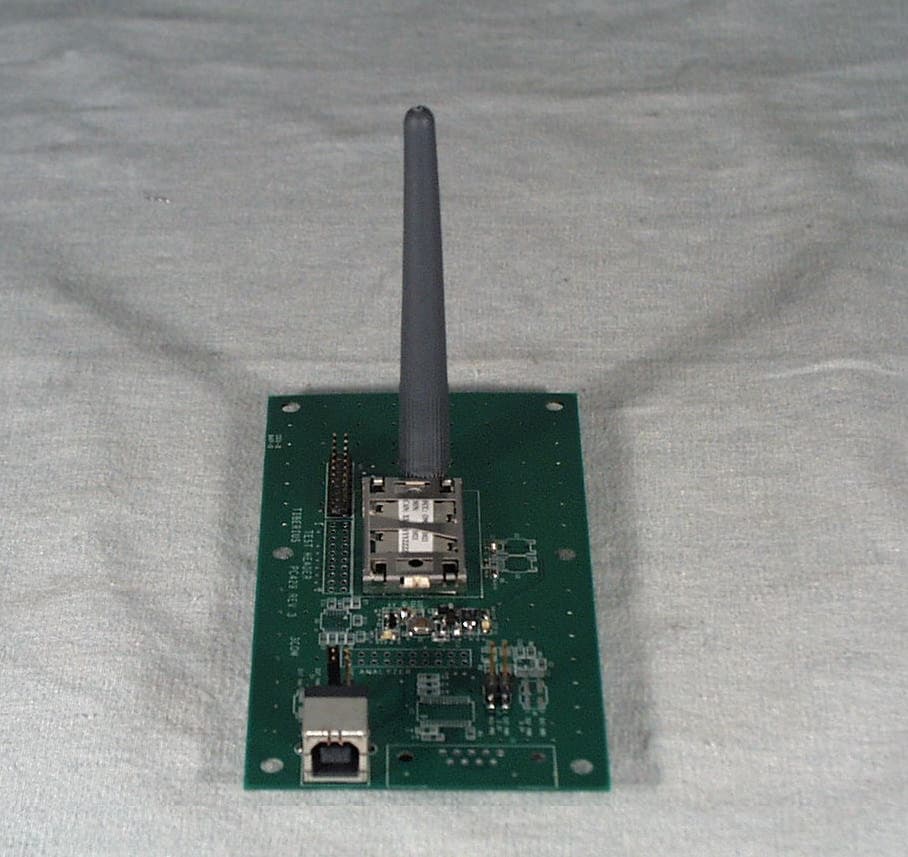
Click to zoom
Application Details
- Equipment Class
- DSS - Part 15 Spread Spectrum Transmitter
- Date of Grant
- Jun 17, 2001
- Application Purpose
- Original Equipment
- Date of Application
- May 02, 2001
- Equipment Note
- SL-1021
- Frequency Range
- 2402.00000000 - 2480.00000000
- Company
- Hewlett Packard Enterprise
- Country
- United States
Documents & Files
Document Text
Text extracted from the exhibit documents filed with the FCC. Open a document above to read the original.
Users Manual
http://www.3com.com/ http://www.3com.com/productreg Wireless USB Device User Guide Published April 2001 Version 1.1.1 SL-1020, SL-1021 EXHIBIT 8: User / Installation Manual Page 1 of 21 3Com Corporation n 5400 Bayfront Plaza n Santa Clara, California n 95052-8145 Copyright © 2001 3Com Corporation. All rights reserved. No part of this documentation may be reproduced in any form or by any means or used to make any derivative work (such as translation, transformation, or adaptation) without written permission from 3Com Corporation. 3Com Corporation reserves the right to revise this documentation and to make changes in content from time to time without obligation on the part of 3Com Corporation to provide notification of such revision or change. 3Com Corporation provides this documentation without warranty, term, or condition of any kind, either implied or expressed, including, but not limited to, the implied warranties, terms or conditions of merchantability, satisfactory quality, and fitness for a particular purpose. 3Com may make improvements or changes in the product(s) and/or the program(s) described in this documentation at any time. If there is any software on removable media described in this documentation, it is furnished under a license agreement included with the product as a separate document, in the hard copy documentation, or on the removable media in a directory file named LICENSE.TXT or !LICENSE.TXT. If you are unable to locate a copy, please contact 3Com and a copy will be provided to you. UNITED STATES GOVERNMENT LEGEND If you are a United States government agency, then this documentation and the software described herein are provided to you subject to the following: All technical data and computer software are commercial in nature and developed solely at private expense. Software is delivered as “Commercial Computer Software” as defined in DFARS 252.227-7014 (June 1995) or as a “commercial item” as defined in FAR 2.101(a) and as such is provided with only such rights as are provided in 3Com’s standard commercial license for the Software. Technical data is provided with limited rights only as provided in DFAR 252.227-7015 (Nov 1995) or FAR 52.227-14 (June 1987), whichever is applicable. You agree not to remove or deface any portion of any legend provided on any licensed program or documentation contained in, or delivered to you in conjunction with, this User Guide. Unless otherwise indicated, 3Com registered trademarks are registered in the United States and may or may not be registered in other countries. 3Com and DynamicAccess are registered trademarks and the 3Com logo is a trademark of 3Com Corporation. XTNDConnect PC is a registered trademark of Extended Systems. Microsoft and Windows are registered trademarks of Microsoft Corporation. All other company and product names may be trademarks of the respective companies with which they are associated. EXHIBIT 8: User / Installation Manual Page 2 of 21 C ONTENTS I NTRODUCTION TO W IRELESS T ECHNOLOGY Overview Wireless USB Device Optimized Antenna Software and Firmware Upgradeable I NSTALLING Y OUR USB D EVICE AND C ONNECTION M ANAGER Installation CD Installing Your External USB Device and Virtual COM Ports Using Connection Manager Confirming Device Installation Reinstalling Drivers for Your Embedded USB Device Uninstalling Your USB Device and Virtual COM Ports Technical Support R EGULATORY I NFORMATION EXHIBIT 8: User / Installation Manual Page 3 of 21 1 I NTRODUCTION TO W IRELESS T ECHNOLOGY Overview wirel ess tec hnology allows you to make short-range wireless connections to devices such as cellular phones, persona l digital assistants (PDA), and desktop and notebook computers. Because wireless technology uses radio transmission, voice and data transmission are immediate. The mode of tr ansmission that w ireless tec hnology uses ensures both protection from interference and secure data transfers. You might use wireless technology in these ways: n Dial up to the Internet on your noteb ook over your cellula r phone n Send a fax from your noteb ook over your cellular phone n Synchronize your P DA with your noteb ook n Send your business card to anyone in a meeting who has a device n Se nd or receive files from anyone in a mee ting who has a n otebook or PDA n Chat with anyone in a meeting who has a notebook n Play a one-on-one serial game without a cable n Send an e-mail from your training session without being wired to the network Wireless USB Device The USB device uses a reliable radio frequency to tr ansmit data wirelessly. Optimized Antenna The anten na provides powerful perf ormance in all directions. Software and Firmware Upgradeable Current software and firmware upgrades are available on the 3Com Web site at: www.support.3com.com EXHIBIT 8: User / Installation Manual Page 4 of 21 2 I NSTALLING Y OUR USB D EVICE AND C ONNECTION M ANAGER Insta llation CD The Ins tallation CD contains the following: n Microsoft Windows 98 Second Edition (SE), 2000, and Millennium Edition (Me) setup programs and drivers Connection Manager by 3Com n XTNDConnect PC mobile synchronization and management software n 3Com Mobile Connection Manager n README.TXT file with updated information about your U SB device n This Wireless USB Device User Guide n Adobe Acrobat Reader Installing Your External USB Device and Virtual COM Ports 1 With the computer on and Windows 98 SE, 2000, or Me running,insert the Installation CD into the CD-ROM driv e. The auto-start featu re starts the installation. If auto-start is disabled on your computer, click Start>Run and type D:\SETUP.EXE (where D: is your CD-ROM drive). 2 Select Install Hardware . 3 Attach the USB device to the USB port (see the first illustration below). You are prompted to “Add new Hardware.” After attaching the USB device, if auto-start is enabled and nothing happens within five seconds, restart your computer and log in to Windows. The installation process will begin when the computer restarts.…
Text truncated - open the document above for the full version.
Cover Letter(s)
3Com Corporation April 19, 2001 3930 W. Parkway Blvd. West Valley, UT 84119 FEDERAL COMMUNICATIONS COMMISSION 7435 Oakland Mills Road Columbia, MD 21046 Dear Application Examiner: 3Com Corporation is submitting this application for the certification of the 3Com SL-1021 wireless module. It operates in the 2400 – 24835 MHz band, with a peak output power of 1.1 mW. It is a spread spectrum transmitter that utilizes frequency hopping techniques. This RF module will be used in personal computers and peripherals (both in desktop and notebook platforms) as a portable transmitter. SL-1021 can be configured with any one of eleven antenna types. Data is supplied with this application in support of each antenna type. The technical report and exhibits demonstrate compliance with FCC rules 47 CFR 15.247, Public Notice DA 00-705, and FCC 97-114. In addition, the EUT meets the requirements for modular approval as detailed in FCC Public Notice DA 00-1407. Compliance to each of the modular approval requirements is described in this Exhibit 13, found in the file named “Exhibit_13.pdf”. To facilitate the review process an index of exhibits has been provided within this same file. Thank you for reviewing this application. Best regards, Kaan L. Gregersen Regulatory Engineer 3Com Corporation 3Com Corporation April 19, 2001 3930 W. Parkway Blvd. West Valley, UT 84119 FEDERAL COMMUNICATIONS COMMISSION 7435 Oakland Mills Road Columbia, MD 21046 Dear Application Examiner: The following information is in regards to compliance of the 3Com SL-1021 to the requirements for modular approval detailed in FCC Public Notice DA 00-1407. As the requirements are listed in DA 00-1407, compliance is described below: 1. RF shielding – The radio transmitter circuitry is contained within a copper and tinned copper RF shield that is comprised of a plain on the PCB and a metal shield that is soldered to the PCB. Please refer to Exhibit 1 for photographs of the RF shield. 2. Buffered modulation/data inputs – The buffer is provided on SL-1021 and is shown in the schematic. Please refer to Exhibit 5. 3. Voltage regulation – Voltage regulation is provided on SL-1021 and is shown in the schematic. Please refer to Exhibit 5. 4. Antenna requirements – Being a module, SL-1021 was documented with several antennas. Please refer to Exhibit 6. 5. Stand alone test configuration – SL-1021 was tested externally to a representative host. Please refer to Exhibit 7 for test setup photographs. 6. Labeling – This information appears on the device. Please refer to Exhibit 1. The installer is advised to also display the labeling information, as required by DA 00-1407, see Exhibit 8. 7. User/Installation instructions - SL-1021 is compliant with all applicable FCC rules. User/installation instructions required for maintaining compliance are given in Exhibit 8. 8. RF Exposure – SL-1021 complies with RF Exposure limits based on the low power output (1 mW), intended distance of the human body from the antenna and the transmitter duty cycle due to modulation and usage. Please refer to Exhibit 11. Best regards, Kaan L. Gregersen Regulatory Engineer 3Com Corporation Index of Exhibits for 3Com SL-1021 Wireless Module FCC ID: O9C-SL1021 EXHIBITDESCRIPTIONFILE NAMECONFIDENTIAL Exhibit 1Labeling and PlacementExhibit_1.pdf Exhibit 2Letter of AttestationExhibit_2.pdf Exhibit 3External View PhotographsExhibit_3.pdf Exhibit 4Block DiagramExhibit_4.pdfYES Exhibit 5SchematicsExhibit_5.pdfYES Exhibit 6Test ReportExhibit_6.pdf Exhibit 7Test Set-up PhotographsExhibit_7.pdf Exhibit 8User Manual and Installation GuideExhibit_8.pdf Exhibit 9Internal View PhotographsExhibit_9.pdf Exhibit 10(Not Applicable)(Not Applicable) Exhibit 11RF Exposure InformationExhibit_11.pdf Exhibit 12Description of OperationExhibit_12.pdfYES Exhibit 13Cover LettersExhibit_13.pdf
Cover Letter(s)
3Com Corporation April 19, 2001 3930 W. Parkway Blvd. West Valley, UT 84119 FEDERAL COMMUNICATIONS COMMISSION 7435 Oakland Mills Road Columbia, MD 21046 Subject: Request for Confidentiality Regarding FCC ID: O9C-SL1021 To Whom It May Concern: In accordance with § 0.459 of CFR 47, 3Com Corporation requests confidentiality for the following items: 1. Block Diagram (Exhibit 4) 2. Schematic Diagrams (Exhibit 5) 3. Operational Description (Exhibit 12) These items contain detailed system and equipment description and related information about the product which 3Com Corporation considers to be proprietary, confidential and a custom design which otherwise would not be released to the general public. Since this design is a basis from which future technological products will evolve, 3Com Corporation also feels that this information would be of benefit to its competitors, and that the disclosure of the information in these exhibits would give our competitors an unfair advantage in the market. Any information for which 3Com has requested confidentiality, but which the FCC may not grant, should be returned to 3Com. Best Regards, Kaan L. Gregersen Regulatory Engineer 3930 West Parkway Blvd. West Valley City, UT 84119 (801) 320-7515
External Photos
EXHIBIT 3: External Photographs Page 1 of 2 Side View of the Tiberius Test Platform EXHIBIT 3: External Photographs Page 2 of 2 End View of the Tiberius Test Platform
ID Label/Location Info
Page 1 of 1
Internal Photos
EXHIBIT 9: Internal Photographs Front View of the SL-1021 Page 1 of 2 EXHIBIT 9: Internal Photographs Back View of the SL-1021 Page 2 of 2
RF Exposure Info
EXHIBIT 11: RF Statement Page 1 of 1 RF Exposure Compliance Requirements Per 47 CFR 15.247 (b)(4), the EUT meets the requirement that it be operated in a manner that ensures the public is not exposed to radio frequency energy levels in excess of the Commission’s guidelines (ref. 47 CFR 1.1307, 1.1310, and 2.1093. See also OET Bulletin 65, Supplement C). The EUT will be used in personal computers and peripherals and can therefore be considered a portable transmitter per 47 CFR 2.1093. The EUT supports the connection of only one antenna at a time. The MPE estimates are as follows: Table 1 in 47 CFR 1.1310 defines the maximum permissible exposure (MPE) for the general population as 1mW/cm 2 . The distance from the EUT’s transmitting antenna where the exposure level reaches the maximum permitted level is calculated using the general equation: S = (PG)/4πR 2 . Where: S = power density (1 mW/cm 2 maximum permitted level) P = power input to the antenna (1.1 mW) G = linear power gain relative to an isotropic radiator (4 dBi = numeric gain of 2.5) R = distance to the center of the radiation of the antenna Solving for R, the 1 mW/cm 2 limit is reached 0.47 cm or closer to the transmitting antenna. Therefore, no warning labels, no RF exposure warnings in the user manual, or other protection measures will be used with the EUT. Installation instructions will include the following information: “This device generates and radiates radio-frequency energy. In order to comply with FCC radio-frequency radiation exposure guidelines for an uncontrolled environment, this device must be installed and operated while maintaining a minimum body to antenna distance of 0.47 cm (0.185 inch), based on an antenna gain of 4 dBi. Contact 3Com for additional information regarding minimum body to antenna distances based on antenna gains other than 4 dBi.”
Test Report
TEST REPORT FROM: COMMUNICATION CERTIFICATION LABORATORY 1940 W. Alexander Street Salt Lake City, Utah 84119-2039 Type of Report: Certification TEST OF: SL-1021 FCC ID: O9C-SL1021 To FCC PART 15.247, Subpart C Test Report Serial No: 73-7455 Applicant: 3Com Corporation 3930 West Parkway Blvd. West Valley City, UT 84119 Date(s) of Test: February 16 & 20, 2001 Issue Date: March 30, 2001 Equipment Receipt Date: February 16, 2001 COMMUNICATION CERTIFICATION LABORATORY TEST REPORT: 73-7455 FCC ID: O9C-SL1021 Page 2 of 144 TABLE OF CONTENTS PAGE SECTION 1. CLIENT INFORMATION AND MANUFACTURER: .................3 SECTION 2. EQUIPMENT UNDER TEST (EUT) ...........................4 SECTION 3. TEST SPECIFICATION, METHODS & PROCEDURES .............7 SECTION 4. OPERATION OF EUT DURING TESTING. ....................12 SECTION 5. SUMMARY OF TEST RESULTS: ............................13 SECTION 6. MEASUREMENTS, EXAMINATIONS AND DERIVED RESULTS: .....14 APPENDIX 1 TEST PROCEDURES AND TEST EQUIPMENT ..................108 APPENDIX 2 Photographs .........................................116 APPENDIX 2 RF Exposure/Environmental Evaluation ................143 COMMUNICATION CERTIFICATION LABORATORY TEST REPORT: 73-7455 FCC ID: O9C-SL1021 Page 3 of 144 SECTION 1. CLIENT INFORMATION AND MANUFACTURER: 1.1 Client Information: Company Name: 3Com Corporation 3930 West Parkway Blvd. West Valley City, UT 84119 Contact Name: Kaan Gregersen Title: Regulatory Engineer 1.2 Manufacturer: Company Name: 3Com Corporation 3930 West Parkway Blvd. West Valley City, UT 84119 Contact Name: Kaan Gregersen Title: Regulatory Engineer COMMUNICATION CERTIFICATION LABORATORY TEST REPORT: 73-7455 FCC ID: O9C-SL1021 Page 4 of 144 SECTION 2. EQUIPMENT UNDER TEST (EUT) 2.1 Identification of EUT: Trade Name: 3Com Corporation Model Name or Number: SL-1021 Serial Number: N/A Options Fitted: None Country of Manufacture: U.S.A. 2.2 Description of EUT: The 3Com M/N SL-1021 is a spread spectrum frequency hopping transceiver that operates in the 2.4000 to 2.4835 MHz band. This device is intended for installation within a host and provides a wireless connection to other like devices at a data rate of approx. 1 Mbps. The SL-1021 will install into a socket or may be soldered directly to the host motherboard. The communication interface between the SL-1021 and the host is a USB or serial type interface. Connection to the antenna, which may also be installed within the host, is provided through the wireless device to host interface. This report covers the transmitter only. The receiver and class B computer peripheral are covered under a separate declaration of conformity report. 2.3 Modification Incorporated/Special Accessories on EUT: There were no modifications or special accessories required to comply with the specification. 2.4 EUT and Support Equipment: The FCC ID numbers for all the EUT and support equipment used during the test (including inserted cards) are listed below: Brand Name Model Number FCC ID Number Description Name of Interface Ports / Interface Cables COMMUNICATION CERTIFICATION LABORATORY TEST REPORT: 73-7455 FCC ID: O9C-SL1021 Page 5 of 144 Brand Name Model Number FCC ID Number Description Name of Interface Ports / Interface Cables BN: 3Com (1) MN: SL-1021 O9C- SL1021 Direct Sequence Spread Spectrum Device See Section 2.5. BN: 3Com MN: Tiberius SN: N/A N/A Test Platform See Section 2.5. BN: Dell MN: Inspiron 4000 SN: TW-07914H-12800- 11B-0882 DoC Laptop Computer USB / USB to Mini USB cable Note: (1) EUT. (2) Interface port connected to EUT (See Section 2.5) (3) Mouse cable permanently attached. The support equipment listed above was not modified in order to achieve compliance with this standard. 2.5 Interface Ports on EUT: Name of Ports No. of Ports Fitted to EUT. Cable Descriptions/Length N/A N/A The SL-1021 is either installed into a socket or soldered directly to the host motherboard COMMUNICATION CERTIFICATION LABORATORY TEST REPORT: 73-7455 FCC ID: O9C-SL1021 Page 6 of 144 2.6 List of Channels: Channel Number Channel Frequency (MHz) Channel Number Channel Frequency (MHz) 1 2402.0 41 2442.0 2 2403.0 42 2443.0 3 2404.0 43 2444.0 4 2405.0 44 2445.0 5 2406.0 45 2446.0 6 2407.0 46 2447.0 7 2408.0 47 2448.0 8 2409.0 48 2449.0 9 2410.0 49 2450.0 10 2411.0 50 2451.0 11 2412.0 51 2452.0 12 2413.0 52 2453.0 13 2414.0 53 2454.0 14 2415.0 54 2455.0 15 2416.0 55 2456.0 16 2417.0 56 2457.0 17 2418.0 57 2458.0 18 2419.0 58 2459.0 19 2420.0 59 2460.0 20 2421.0 60 2461.0 21 2422.0 61 2462.0 22 2423.0 62 2463.0 23 2424.0 63 2464.0 24 2425.0 64 2465.0 25 2426.0 65 2466.0 26 2427.0 66 2467.0 27 2428.0 67 2468.0 28 2429.0 68 2469.0 29 2430.0 69 2470.0 30 2431.0 70 2471.0 31 2432.0 71 2472.0 32 2433.0 72 2473.0 33 2434.0 73 2474.0 34 2435.0 74 2475.0 35 2436.0 75 2476.0 36 2437.0 76 2477.0 37 2438.0 77 2478.0 38 2439.0 78 2479.0 39 2440.0 79 2480.0 40 2441.0 COMMUNICATION CERTIFICATION LABORATORY TEST REPORT: 73-7455 FCC ID: O9C-SL1021 Page 7 of 144 SECTION 3. TEST SPECIFICATION, METHODS & PROCEDURES 3.1 Test Specification: Title: FCC PART 15.247, Subpart C (47 CFR 15). Limits and methods of measurement of radio interference characteristics of radio frequency devices. Operation within the bands 902-928 MHz, 2400-2483.5 MHz and 5725-5850 MHz. Purpose of Test: The tests were performed to demonstrate Initial compliance. 3.2 Methods & Procedures: 3.2.1 § 15.247 (a) Operation under the provisions of this section is limited to frequency hopping and direct sequence spread spectrum intentional radiators that comply with the following provisions: (1) Frequency hopping systems shall have hopping channel carrier frequencies separated by a minimum of 25 kHz or the 20 dB bandwidth of the hopping channel, whichever is greater. The system shall hop to channel frequencies that are selected at the system hopping rate from a pseudorandomly ordered list of hopping frequencies. Each frequency must be used equally on the average by each transmitter. The system receivers shal…
Text truncated - open the document above for the full version.
Test Setup Photos
Front View of Radiated Test Setup Back View Of Radiated Test Setup
Contact Information
Applicant
Jim Taylor(Manager, Hardware Support Engineering)
Test Firm
Communication Certification Lab.Scott Earl
Technical Specifications
| # | Rule Parts | Frequency Range | Power Output |
|---|---|---|---|
| 1 | 15C | 2.40 GHz - 2.48 GHz | 1.28 mW |
Other Applications from Hewlett Packard Enterprise

O9C-BJNGABB0038
Oct 29, 2015HPE MSR954-W 1GbE+SFP LTE (AM) Rtr
Equipment Class
DTS - Digital Transmission System
O9C-BJNGAFB0008
Jul 30, 2015Wireless LAN Access Point
Equipment Class
JBP - Part 15 Class B Computing Device Peripheral
O9C-BJNGAFB0005
Nov 06, 2014Unified Wired-WLAN Walljack
Equipment Class
JBP - Part 15 Class B Computing Device Peripheral
O9C-BJNGAFB0004
Sep 04, 2014Wireless LAN Access Point
Equipment Class
JBP - Part 15 Class B Computing Device Peripheral
O9C-BJNGAFB0003
Jul 02, 2014Unified Wired-WLAN Walljack
Equipment Class
DTS - Digital Transmission System