O9C-SL304511a/b/g Wireless PCI Adapter
Hewlett Packard Enterprise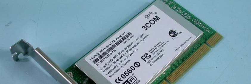
Click to zoom
Application Details
- Equipment Class
- NII - Unlicensed National Information Infrastructure TX
- Date of Grant
- Nov 04, 2003
- Application Purpose
- Original Equipment
- Date of Application
- Nov 04, 2003
- Equipment Note
- 11a/b/g Wireless PCI Adapter
- Frequency Range
- 5725.00000000 - 5825.00000000
- Company
- Hewlett Packard Enterprise
- Country
- United States
Documents & Files
Document Text
Text extracted from the exhibit documents filed with the FCC. Open a document above to read the original.
Users Manual
Wireless LAN PC Card 3CRPAG175 Wireless LAN PCI Adapter 3CRDAG675 Quick Start Guide http://www.3com.com/ Published October 2003 Quick start guide version 1.0.0 3Com Corporation ■ 350 Campus Drive ■ Marlborough, MA ■ USA 01752 Copyright © 2003 3Com Corporation. All rights reserved. No part of this documentation may be reproduced in any form or by any means or used to make any derivative work (such as translation, transformation, or adaptation) without written permission from 3Com Corporation. 3Com Corporation reserves the right to revise this documentation and to make changes in content from time to time without obligation on the partof 3Com Corporation to provide notification of such revision or change. 3Com Corporation provides this documentation without warranty, term, or condition of any kind, either implied or expressed, including, but not limited to, the implied warranties, terms or conditions of merchantability, satisfactory quality, and fitness for a particular purpose. 3Com may make improvements or changes in the product(s) and/or the program(s) described in this documentation at any time. 3Com is a registered trademark and the 3Com logo is a trademark of 3Com Corporation. Microsoft and Windows are registered trademarks of Microsoft Corporation. All other company and product names may be trademarks of the respective companies with which they are associated. Unless otherwise indicated, 3Com registered trademarks are registered in the United States and may or may not be registered in other countries. If there is any software on removable media described in this documentation, it is furnished under a license agreement included with the product as a separate document or in the hard copy documentation. If you are unable to locate a copy, please contact 3Com and a copy will be provided to you. UNITED STATES GOVERNMENT LEGEND If you are a United States government agency, then this documentation and the software described herein are provided to you subject to the following: All technical data and computer software are commercial in nature and developed solely at private expense. Software is delivered as "Commercial Computer Software" as defined in DFARS 252.227-7014 (June 1995) or as a "commercial item" as defined in FAR 2.101(a) and as such is provided with only such rights as are provided in 3Com's standard commercial license for the software. Technical data is provided with limited rights only as provided in DFAR 252.227-7015 (Nov 1995) or FAR 52.227-14 (June 1987), whichever is applicable. You agree not to remove or deface any portion of any legend provided on any licensed program or documentation contained in, or delivered to you in conjunction with, this user guide. Contents 1Installing Your Wireless LAN Product and Wireless LAN Manager 1 Installation CD1 Installing your Wireless LAN PC Card: 1 Windows XP, 2000, Me, and 98 SE Installation1 Inserting Your Wireless LAN PC Card2 Antennas 2 Installing Your Wireless LAN PCI Adapter3 Install Procedure for Microsoft Windows 98SE/ME/2000/XP3 Installing the PCI Adapter into your system4 Using Wireless LAN Manager7 Getting Connected with 3Com Wireless LAN Manager7 Creating New Connections 8 2Troubleshooting11 Confirming Device Installation11 Diagnosing Problems11 Wireless LAN Adapter LED Indicators 12 Removing Your Wireless LAN PC Card12 Updating the Wireless LAN Product Driver12 Windows XP and 200012 Windows Me and 98 SE13 ATechnical Support15 Online Technical Services 15 World Wide Web Site15 3Com Knowledgebase Web Services15 3Com FTP Site15 Support from Your Network Supplier16 Support from 3Com16 Returning Products for Repair16 Regulatory Compliance Information17 FCC Part 15 Notice (Applicable to use within the USA)17 Unintentional Radiator 17 Manufacturer’s Declaration of Conformity18 Industry Canada Notice (Applicable for use within Canada)18 Avis de conformité à la réglementation d’Industrie Canada18 Safety Notice19 European Community CE Notice19 Contents 1 1 Installing Your Wireless LAN Product and Wireless LAN Manager Installation CD The Installation CD contains: ■Setup programs and drivers for Windows XP, 2000, Millennium Edition (Windows Me), 98 Second Edition (SE) ■3Com Wireless LAN Manager ■README.TXT file with updated information about your Wireless LAN Product ■This Wireless LAN Quick Start Guide ■Adobe Acrobat Reader Installing your Wireless LAN PC Card: Windows XP, 2000, Me, and 98 SE Installation If you are accessing this guide as part of your LAN PC Card installation, skip to step 2 below. 1With the computer on and Windows running, insert the Installation CD into the CD-ROM drive. The auto-start feature starts the installation. If nothing happens within five seconds, click Start > Run and type d:\setup.exe (where d: is your CD-ROM drive). 2From the 3Com Wireless Installer main menu, select Install Wireless Product. 3Wait for the installation program to prompt you to insert the PC Card into the slot (see the illustrations in the next section, "Inserting Your Wireless LAN PC Card"). 4Your machine will run through the hardware installation and automatically launch the Wireless LAN Manager software installation. Respond to the prompts as they appear. 5During the installation process, you may receive prompts for the Windows installation CD. Insert the CD for your Windows operating system and indicate the correct path. Your computer goes through a brief installation process during which it displays several windows indicating what is currently installing. 6Restart the computer whenever you are prompted to do so. 7When Wireless LAN Manager starts, you will be prompted to select the country where you will be using the 3CRPAG175 Wireless LAN PC Card. It is very important that you select the correct country so the product is properly configured for that country. 8Your installation is now complete. NOTE: To simplify installation, please insert CD and run setup before inserting PC Card. 1Installing Your Wireless LAN Product and Wireless…
Text truncated - open the document above for the full version.
Cover Letter(s)
3Com Corporation 3930 W. Parkway Blvd. West Valley City, UT 84120-6300 USA Tel : 801-320-7585, Fax: 801-320-6280 AGENCY AUTHORIZATION LETTER Date: October 24, 2003 To whom it may concern: We, the undersigned, hereby authorize Advance Data Technology Corp. (ADT) of Taiwan to act on our behalf, as our agent, in the following matters related to the FCC approval of our products: report submittal, related correspondence, the signing of all documents relating to these matters, and any other lawful activity necessary to obtain such certification. Any act carried out by ADT within the scope of this authorization shall have the same effects as our own. This authorization shall expire six months from original date. If you have any questions regarding the authorization, please don’t hesitate to contact us. Thank you! Sincerely, Greg Hansen / Regulatory Engineer 3Com Corporation Tel.: 801-320-7585 Fax: 801-320-6280 e-mail: [email protected]
Cover Letter(s)
3Com Corporation 3930 W. Parkway Blvd. West Valley City, UT 84120-6300 USA Tel : 801-320-7585, Fax: 801-320-6280 FEDERAL COMMUNICATIONS COMMISSION DECLARATION OF CONFORMITY (DoC) For the following equipment: Product Name: 11a/b/g Wireless PCI Adapter Model Name: 3CRDAG675 Trade Name: 3Com is herewith confirmed to be in compliance with the requirements of ANSI C63.4 & FCC part 15 regulations. The test result has been shown in the ADT test report with number D921003R02. And this compliance is subject to the following two conditions: (1) This device may not cause harmful interference and, (2) This device must accept any interference received, including interference that may cause undesired operation. The following local Manufacturer/Importer is responsible for this declaration: 3Com Corporation (Company Name) 3930 W. Parkway Blvd. West Valley City, UT 84120-6300 USA (Company Address) TEL: 801-320-7585 e-mail : [email protected] Greg Hansen / Regulatory Engineer (Name) (Title) October 24, 2003 (Signature) (Date)
Cover Letter(s)
3Com Corporation 3930 W. Parkway Blvd. West Valley City, UT 84120-6300 USA Tel : 801-320-7585, Fax: 801-320-6280 Date: October 24 , 2003 FCC ID: O9C-SL3045 Federal Communications Commission Authorization and Evaluation Division Confidentiality Request Pursuant to Sections 0.457 and 0.459 of the Commission’s Rules, the Applicant hereby requests confidential treatment of information accompanying this Application as outlined below: Schematics Block Diagram Theory of Operations The above materials contain trade secrets and proprietary information not customarily released to the public. The public disclosure of these matters might be harmful to the Applicant and provide unjustified benefits to its competitors. The Applicant understands that pursuant to Rule 0.457, disclosure of this Application and all accompanying documentation will not be made before the date of the Grant for this application. Sincerely, Greg Hansen / Regulatory Engineer 3Com Corporation Tel.: 801-320-7585 Fax: 801-320-6280 e-mail: [email protected] e-mail : [email protected]
External Photos
Page 1 CONSTRUCTION PHOTOS OF EUT Page 2 Page 3 Page 4
Internal Photos
Page 5 Page 6 Page 7
Operational Description
FCC ID: O9C-SL3045 Report No.921003R02 Operational Description The transmitter of the EUT is powered by host equipment. The antenna is Dipole antenna without antenna connector. This device is 11a/b/g Wireless PCI Adapter operates in both the 5GHz and 2.4GHz bands and can’t transmitting simultaneously, the maximum data rate could be 54Mbps. (turbo mode :108 Mbps) For more detailed instruction, please take a look at the user’s manual. FCC 15.407(c) states : The device shall automatically discontinue transmission in case of either absence of information to transmit or operational failure. These provisions are not intended to preclude the transmission of control or signaling information or the use of repetitive codes used by certain digital technologies to complete frame or burst intervals. Applicants shall include in their application for equipment authorization a description of hoe this requirement is met” Data transmission is always initiated by software, which is then pass down through the MAC, through the digital and analog baseband, and finally to the RF chip. Several special packets (ACKs, CTS, PSPoll, etc...) are initiated by the MAC. There are the only ways the digital baseband portion will turn on the RF transmitter, which it then turns off at the end of the packet. Therefore, the transmitter will be on only while one of the aforementioned packets are being transmitted.
RF Exposure Info
FCC ID: O9C-SL3045 Report No: RF921003R02 1 RF EXPOSURE REPORT REPORT NO.: RF921003R02 MODEL NO.: 3CRDAG675 ACCORDING: FCC Guidelines for Human Exposure IEEE C95.1 APPLICANT: 3Com Corporation ADDRESS: 3930 West Parkway Blvd., West Valley City, Utah 84120, U.S.A. ISSUED BY: Advance Data Technology Corporation LAB LOCATION: 47 14th Lin, Chiapau Tsun, Linko, Taipei, Taiwan, R.O.C. 0528 ILAC MRA Lab Code: 200102-0 FCC ID: O9C-SL3045 Report No: RF921003R02 2 RF Exposure Measurement (Mobile Device) 1. Introduction In this document, we try to prove the safety of radiation harmfulness to the human body for our product. The limit for Maximum Permissible Exposure (MPE) specified in FCC 1.1310 is followed. The Gain of the antenna used in this product is measured in a Fully Anechoic Chamber (FAC) calibrated for antenna measurement in ADT, and also the maximum total power input to the antenna is measured. Through the Friis transmission formula and the maximum gain of the antenna, we can calculate the distance, away from the product, where the limit of MPE is reached. Although the Friis transmission formula is a far field assumption, the calculated result of that is an over-prediction for near field power density. We will take that as the worst case to specify the safety range. 2. RF Exposure Limit According to FCC 1.1310: The criteria listed in the following table shall be used to evaluate the environmental impact of human exposure to radio-frequency (RF) radiation as specified in 1.1307(b) LIMITS FOR MAXIMUM PERMISSIBLE EXPOSURE (MPE) Frequency Range (MHz) Electric Field Strength (V/m) Magnetic Field Strength (A/m) Power Density (mW/cm 2 ) Average Time (minutes) (A)Limits For Occupational / Control Exposures 300-1500......F/3006 1500-100,000......56 (B)Limits For General Population / Uncontrolled Exposure 300-1500......F/15006 1500-100,000......1.030 F = Frequency in MHz FCC ID: O9C-SL3045 Report No: RF921003R02 3 3. Friis Formula Friis transmission formula : Pd = (Pout*G) / (4*pi*r 2 ) where Pd = power density in mW/cm 2 Pout = output power to antenna in mW G = gain of antenna in linear scale Pi = 3.1416 R = distance between observation point and center of the radiator in cm Pd is the limit of MPE, 1 mW/cm 2 . If we know the maximum Gain of the antenna and the total power input to the antenna, through the calculation, we will know the MPE value at distance 20cm. Ref. : David K. Cheng, Field and Wave Electromagnetics, Second Edition, Page 640, Eq. (11-133). 4 EUT Operating condition The software provided by Manufacturer enabled the EUT to transmit and receive data at lowest, middle and highest channel individually. 5. Classification The antenna of the product, under normal use condition, is at least 20cm away from the body of the user. Warming statement for keeping 20cm separation distance and the prohibition of operating next to a person has been printed on the user’s manual. So, this product is classified as the Mobile Device. FCC ID: O9C-SL3045 Report No: RF921003R02 4 6 Test Results 6.1 Antenna Gain The maximum Gain measured in Fully Anechoic Chamber is 0dBi or 1 (numeric) for 2.4GHz band, and 0dBi or 1 (numeric) for 5GHz band. 6.2 Output Power Into Antenna & MPE value at distance 20cm : For Part 802.11b (CCK technique): Channel Channel Frequency (MHz) Output Power to Antenna (mW) Power Density (mW/cm 2 ) Limit of Power Density (mW/cm 2 ) 1241284.330.0171 6243786.700.0171 11246280.720.0161 For Part 802.11g (OFDM technique with Normal mode): Channel Channel Frequency (MHz) Output Power to Antenna (mW) Power Density (mW/cm 2 ) Limit of Power Density (mW/cm 2 ) 1241252.240.0101 6243753.210.0111 11246252.720.0101 For Part 802.11g (OFDM technique with Turbo mode): Channel Channel Frequency (MHz) Output Power to Antenna (mW) Power Density (mW/cm 2 ) Limit of Power Density (mW/cm 2 ) 6243758.480.0121 FCC ID: O9C-SL3045 Report No: RF921003R02 5 For Part 802.11a (Normal Mode): Channel Channel Frequency (MHz) Output Power to Antenna (mW) Power Density (mW/cm 2 ) Limit of Power Density (mW/cm 2 ) 1518040.550.0081 4524039.360.0081 5526051.050.0101 8532045.500.0091 9574553.950.0111 12580552.600.0101 For Part 802.11a (Turbo Mode): Channel Channel Frequency (MHz) Output Power to Antenna (mW) Power Density (mW/cm 2 ) Limit of Power Density (mW/cm 2 ) 1521044.770.0091 2525041.500.0081 3529042.070.0081 4576054.330.0111 5580052.600.0101
Test Report
FCC ID: O9C-SL3045 Report No.: RF921003R021Issued: October 9, 2003 FCC TEST REPORT REPORT NO.: RF921003R02 MODEL NO.: 3CRDAG675 RECEIVED: Oct. 3, 2003 TESTED: Sept. 29 ~ Oct. 8, 2003 APPLICANT: 3Com Corporation ADDRESS: 3930 West Parkway Blvd., West Valley City, Utah 84120, U.S.A. ISSUED BY: Advance Data Technology Corporation LAB LOCATION: 47 14 th Lin, Chiapau Tsun, Linko, Taipei, Taiwan, R.O.C. This test report consists of 166 pages in total. It may be duplicated completely for legal use with the approval of the applicant. It should not be reproduced except in full, without the written approval of our laboratory. The client should not use it to claim product endorsement by CNLA, NVLAP or any government agencies. The test results in the report only apply to the tested sample. 0528 ILAC MRA Lab Code: 200102-0 FCC ID: O9C-SL3045 Report No.: RF921003R022Issued: October 9, 2003 Table of Contents 1.CERTIFICATION .................................................................................................................... 6 2.SUMMARY OF TEST RESULTS............................................................................................ 7 3.GENERAL INFORMATION .................................................................................................... 9 3.1GENERAL DESCRIPTION OF EUT....................................................................................... 9 3.2DESCRIPTION OF TEST MODES....................................................................................... 10 3.3GENERAL DESCRIPTION OF APPLIED STANDARDS...................................................... 11 3.4DESCRIPTION OF SUPPORT UNITS................................................................................. 12 4.TEST TYPES AND RESULTS (for part 802.11b & 802.11g) ................................................ 13 4.1CONDUCTED EMISSION MEASUREMENT....................................................................... 13 4.1.1LIMITS OF CONDUCTED EMISSION MEASUREMENT .................................................... 13 4.1.2TEST INSTRUMENTS ......................................................................................................... 13 4.1.3TEST PROCEDURES .......................................................................................................... 14 4.1.4DEVIATION FROM TEST STANDARD ................................................................................ 14 4.1.5TEST SETUP ....................................................................................................................... 15 4.1.6EUT OPERATING CONDITIONS......................................................................................... 15 4.1.7TEST RESULTS ................................................................................................................... 16 4.2RADIATED EMISSION MEASUREMENT............................................................................ 22 4.2.1LIMITS OF RADIATED EMISSION MEASUREMENT ......................................................... 22 4.2.2TEST INSTRUMENTS ......................................................................................................... 23 4.2.3TEST PROCEDURES .......................................................................................................... 24 4.2.4DEVIATION FROM TEST STANDARD ................................................................................ 24 4.2.5TEST SETUP ....................................................................................................................... 25 4.2.6EUT OPERATING CONDITIONS......................................................................................... 25 4.2.7TEST RESULTS ................................................................................................................... 26 4.2.8TEST RESULTS (A) ............................................................................................................. 27 4.2.9TEST RESULTS (B) ............................................................................................................. 30 4.2.10 TEST RESULTS (C) ............................................................................................................. 33 4.36dB BANDWIDTH MEASUREMENT ................................................................................... 34 4.3.1LIMITS OF 6dB BANDWIDTH MEASUREMENT ................................................................ 34 4.3.2TEST INSTRUMENTS ......................................................................................................... 34 4.3.3TEST PROCEDURE ............................................................................................................35 4.3.4DEVIATION FROM TEST STANDARD ................................................................................ 35 4.3.5TEST SETUP ....................................................................................................................... 35 4.3.6EUT OPERATING CONDITIONS......................................................................................... 35 4.3.7TEST RESULTS (A) ............................................................................................................. 36 4.3.8TEST RESULTS (B) ............................................................................................................. 40 4.3.9TEST RESULTS (C) ............................................................................................................. 44 4.4MAXIMUM PEAK OUTPUT POWER ................................................................................... 46 4.4.1LIMITS OF MAXIMUM PEAK OUTPUT POWER MEASUREMENT ................................... 46 FCC ID: O9C-SL3045 Report No.: RF921003R023Issued: October 9, 2003 4.4.2INSTRUMENTS.................................................................................................................... 46 4.4.1TEST PROCEDURES ..........................................................…
Text truncated - open the document above for the full version.
Test Report
FCC ID: O9C-SL3045 Report No.: RF921003R0274Issued: October 9, 2003 5. TEST TYPES AND RESULTS (FOR PART 802.11a) 5.1 CONDUCTED EMISSION MEASUREMENT 5.1.1 LIMITS OF CONDUCTED EMISSION MEASUREMENT FREQUENCY OF EMISSION (MHz)CONDUCTED LIMIT (dBμV) Quasi-peakAverage 0.15-0.5 0.5-5 5-30 66 to 56 56 60 56 to 46 46 50 NOTE:1. The lower limit shall apply at the transition frequencies. 2. The limit decreases in line with the logarithm of the frequency in the range of 0.15 to 0.50 MHz. 3. All emanations from a class A/B digital device or system, including any network of conductors and apparatus connected thereto, shall not exceed the level of field strengths specified above. 5.1.2 TEST INSTRUMENTS DESCRIPTION & MANUFACTURERMODEL NO.SERIAL NO. CALIBRATED UNTIL ROHDE & SCHWARZ Test Receiver ESCS 30838251/021Jan. 20, 2004 ROHDE & SCHWARZ Artificial Mains Network (for EUT) ESH3-Z5100218Dec. 18, 2003 ROHDE & SCHWARZ Artificial Mains Network (for peripherals) ESH3-Z5100219Dec. 18, 2003 ROHDE & SCHWARZ Artificial Mains Network (for peripherals) ESH3-Z5100220Dec. 18, 2003 ROHDE & SCHWARZ 4-wire ISN ENY41837032/016Nov. 29 2003 ROHDE & SCHWARZ 2-wire ISN ENY22837497/016Nov. 29 2003 SoftwareCond-V2M3NANA RF cable (JYEBAO)5D-FBCable-C10.01May 01, 2004 SUHNER Terminator (For ROHDE & SCHWARZ LISN) 65BNC-5001E1-010770Mar. 24, 2004 SUHNER Terminator (For ROHDE & SCHWARZ LISN) 65BNC-5001E1-010773Apr. 06, 2004 NOTE: 1. The calibration interval of the above test instruments is 12 months and the calibrations are traceable to NML/ROC and NIST/USA. 2. “*”: These equipment are used for conducted telecom port test only (if tested). 3. The test was performed in ADT Shielded Room No. 10. 4. The VCCI Site Registration No. is C-1312. FCC ID: O9C-SL3045 Report No.: RF921003R0275Issued: October 9, 2003 5.1.3 TEST PROCEDURES a. The EUT was placed 0.4 meters from the conducting wall of the shielded room with EUT being connected to the power mains through a line impedance stabilization network (LISN). Other support units were connected to the power mains through another LISN. The two LISNs provide 50 ohm/ 50uH of coupling impedance for the measuring instrument. b. Both lines of the power mains connected to the EUT were checked for maximum conducted interference. c. The frequency range from 150kHz to 30MHz was searched. Emission levels over 10dB under the prescribed limits could not be reported 5.1.4 DEVIATION FROM TEST STANDARD No deviation FCC ID: O9C-SL3045 Report No.: RF921003R0276Issued: October 9, 2003 5.1.5 TEST SETUP For the actual test configuration, please refer to the related item – Photographs of the Test Configuration. 5.1.6 EUT OPERATING CONDITIONS Same as 4.1.6 FCC ID: O9C-SL3045 Report No.: RF921003R0277Issued: October 9, 2003 5.1.7 TEST RESULTS MODEL 3CRDAG675 EUT 11a/b/g Wireless PCI Adapter 6dB BANDWIDTH 9 kHz INPUT POWER (SYSTEM) 120Vac, 60 Hz PHASE Line (L) ENVIRONMENTAL CONDITIONS 25deg. C, 70%RH, 991hPa TESTED BY: Martin Lee Freq.Corr. Reading Value Emission Level LimitMargin NoFactor[dB (uV)][dB (uV)][dB (uV)](dB) [MHz](dB)Q.P.AV.Q.P.AV.Q.P.AV.Q.P.AV. 10.2240.0641.44-41.50-62.6652.66-21.16- 20.4740.0738.34-38.41-56.4446.44-18.03- 30.6660.1039.29-39.39-56.0046.00-16.61- 41.8090.1838.11-38.29-56.0046.00-17.71- 54.2850.2338.99-39.22-56.0046.00-16.78- 611.0000.4428.47-28.91-60.0050.00-31.09- REMARKS: 1. Q.P. and AV. are abbreviations of quasi-peak and average individually. 2. "-": The Quasi-peak reading value also meets average limit and measurement with the average detector is unnecessary. 3. The emission levels of other frequencies were very low against the limit. 4. Margin value = Emission level - Limit value 5. Correction factor = Insertion loss + Cable loss 6. Emission Level = Correction Factor + Reading Value. FCC ID: O9C-SL3045 Report No.: RF921003R0278Issued: October 9, 2003 MODEL 3CRDAG675 EUT 11a/b/g Wireless PCI Adapter 6dB BANDWIDTH 9 kHz INPUT POWER (SYSTEM) 120Vac, 60 Hz PHASE Neutral (N) ENVIRONMENTAL CONDITIONS 25deg. C, 70%RH, 991hPa TESTED BY: Martin Lee Freq.Corr. Reading Value Emission Level LimitMargin NoFactor[dB (uV)][dB (uV)][dB (uV)](dB) [MHz](dB)Q.P.AV.Q.P.AV.Q.P.AV.Q.P.AV. 10.2240.0541.93-41.98-62.6652.66-20.68- 20.4740.0638.26-38.32-56.4446.44-18.12- 30.6660.1039.08-39.18-56.0046.00-16.82- 43.0470.1940.48-40.67-56.0046.00 -15.33 - 54.2850.2239.12-39.34-56.0046.00-16.66- 611.0120.4130.58-30.99-60.0050.00-29.01- REMARKS: 1. Q.P. and AV. are abbreviations of quasi-peak and average individually. 2. "-": The Quasi-peak reading value also meets average limit and measurement with the average detector is unnecessary. 3. The emission levels of other frequencies were very low against the limit. 4. Margin value = Emission level - Limit value 5. Correction factor = Insertion loss + Cable loss 6. Emission Level = Correction Factor + Reading Value. FCC ID: O9C-SL3045 Report No.: RF921003R0279Issued: October 9, 2003 5.2 RADIATED EMISSION MEASUREMENT 5.2.1 LIMITS OF RADIATED EMISSION MEASUREMENT Emissions radiated outside of the specified bands, shall be according to the general radiated limits in 15.209 as following: Frequencies (MHz) Field strength (microvolts/meter) Measurement distance (meters) 0.009-0.4902400/F(kHz)300 0.490-1.70524000/F(kHz)30 1.705-30.03030 30-881003 88-2161503 216-9602003 Above 9605003 NOTE: 1. The lower limit shall apply at the transition frequencies. 2. Emission level (dBuV/m) = 20 log Emission level (uV/m). 3. As shown in 15.35(b), for frequencies above 1000MHz, the field strength limits are based on average detector, however, the peak field strength of any emission shall not exceed the maximum permitted average limits, specified above by more than 20dB under any condition of modulation. 5.2.2 LIMITS OF UNWANTED EMISSION OUT OF THE RESTRICTED BANDS Frequencies (MHz) EIRP Limit (dBm) Equivalent Field Strength at 3m (dBμV/m) *note 3 5150~5250-2768.3 5250~5350-2768.3 -27 *note 168.3 5725~5825 -17 *note 278.3 NOTE: 1. For frequencies 10MHz or greater above or below the band e…
Text truncated - open the document above for the full version.
Test Report
FCC ID: O9C-SL3045 Report No.: RF921003R02121Issued: October 9, 2003 5.4 PEAK POWER EXCURSION MEASUREMENT 5.4.1 LIMITS OF PEAK POWER EXCURSION MEASUREMENT Frequency BandLimit 5.15 – 5.25 GHz13dB 5.25 – 5.35 GHz13dB 5.725 – 5.825 GHz13dB 5.4.2 TEST INSTRUMENTS Description & ManufacturerModel No.Serial No.Calibrated Until SPECTRUM ANALYZERFSEK30100049Aug. 12, 2004 SPECTRUM ANALYZER8564EC4208A00660Nov. 20, 2003 NOTE: The calibration interval of the above test instruments is 12 months and the calibrations are traceable to NML/ROC and NIST/USA. FCC ID: O9C-SL3045 Report No.: RF921003R02122Issued: October 9, 2003 5.4.3 TEST PROCEDURE 1. The transmitter output was connected to the spectrum analyzer. 2. Set the spectrum bandwidth span to view the entire spectrum. 3. Using peak detector and Max-hold function for Trace 1 (RB=1MHz, VB=3MHz) and 2 (RB=1MHz, VB=300KHz). 4. The largest difference between Trace 1 and Trace 2 in any 1MHz band on any frequency was recorded. 5.4.4 DEVIATION FROM TEST STANDARD No deviation 5.4.5 TEST SETUP 5.4.6 EUT OPERATING CONDITIONS The software provided by client to enable the EUT under transmission condition continuously at specific channel frequencies individually. EUT SPECTRUM FCC ID: O9C-SL3045 Report No.: RF921003R02123Issued: October 9, 2003 5.4.7 TEST RESULTS EUT 11a/b/g Wireless PCI Adapter MODEL 3CRDAG675 MODE Normal INPUT POWER (SYSTEM) 120Vac, 60 Hz ENVIRONMENTAL CONDITIONS 26deg. C, 62%RH, 991hPa TESTED BY Ansen Lei CHANNEL CHANNEL FREQUENCY (MHz) PEAK POWER EXCURSION (dB) PEAK to AVERAGE EXCURSION LIMIT (dB) PASS/FAIL 151807.8613PASS 452407.9613PASS 552608.8613PASS 853209.2113PASS 957458.3513PASS 1258059.0813PASS FCC ID: O9C-SL3045 Report No.: RF921003R02124Issued: October 9, 2003 CHANNEL 1 FCC ID: O9C-SL3045 Report No.: RF921003R02125Issued: October 9, 2003 CHANNEL 4 FCC ID: O9C-SL3045 Report No.: RF921003R02126Issued: October 9, 2003 CHANNEL 5 FCC ID: O9C-SL3045 Report No.: RF921003R02127Issued: October 9, 2003 CHANNEL 8 FCC ID: O9C-SL3045 Report No.: RF921003R02128Issued: October 9, 2003 CHANNEL 9 FCC ID: O9C-SL3045 Report No.: RF921003R02129Issued: October 9, 2003 CHANNEL 12 FCC ID: O9C-SL3045 Report No.: RF921003R02130Issued: October 9, 2003 EUT 11a/b/g Wireless PCI Adapter MODEL 3CRDAG675 MODE Turbo INPUT POWER (SYSTEM) 120Vac, 60 Hz ENVIRONMENTAL CONDITIONS 26deg. C, 62%RH, 991hPa TESTED BY Ansen Lei CHANNEL CHANNEL FREQUENCY (MHz) PEAK POWER EXCURSION (dB) PEAK to AVERAGE EXCURSION LIMIT (dB) PASS/FAIL 152109.5113PASS 252509.6613PASS 3529010.6613PASS 457609.8313PASS 5580010.8513PASS FCC ID: O9C-SL3045 Report No.: RF921003R02131Issued: October 9, 2003 CHANNEL 1 FCC ID: O9C-SL3045 Report No.: RF921003R02132Issued: October 9, 2003 CHANNEL 2 FCC ID: O9C-SL3045 Report No.: RF921003R02133Issued: October 9, 2003 CHANNEL 3 FCC ID: O9C-SL3045 Report No.: RF921003R02134Issued: October 9, 2003 CHANNEL 4 FCC ID: O9C-SL3045 Report No.: RF921003R02135Issued: October 9, 2003 CHANNEL 5 FCC ID: O9C-SL3045 Report No.: RF921003R02136Issued: October 9, 2003 5.5 PEAK POWER SPECTRAL DENSITY MEASUREMENT 5.5.1 LIMITS OF PEAK POWER S…
Text truncated - open the document above for the full version.
Contact Information
Applicant
Jim Taylor(Manager, Hardware Support Engineering)
Technical Contact
Advance Data Technology Corp.Ellis Wu
[email protected]+886-3-327-0910
13-1 Lane 19 WenShan 3rd Street · Taoyuan · Taiwan
Test Firm
Bureau Veritas CPS (H.K.) Ltd. Taoyuan BranchTommy Wu
Technical Specifications
| # | Rule Parts | Frequency Range | Power Output |
|---|---|---|---|
| 3 | 15E | 5.72 GHz - 5.83 GHz | 54.00 mW |
Other Applications from Hewlett Packard Enterprise

O9C-BJNGABB0038
Oct 29, 2015HPE MSR954-W 1GbE+SFP LTE (AM) Rtr
Equipment Class
DTS - Digital Transmission System
O9C-BJNGAFB0008
Jul 30, 2015Wireless LAN Access Point
Equipment Class
JBP - Part 15 Class B Computing Device Peripheral
O9C-BJNGAFB0005
Nov 06, 2014Unified Wired-WLAN Walljack
Equipment Class
JBP - Part 15 Class B Computing Device Peripheral
O9C-BJNGAFB0004
Sep 04, 2014Wireless LAN Access Point
Equipment Class
JBP - Part 15 Class B Computing Device Peripheral
O9C-BJNGAFB0003
Jul 02, 2014Unified Wired-WLAN Walljack
Equipment Class
DTS - Digital Transmission System