O9C-WL56011a/b/g Wireless Workgroup Bridge
Hewlett Packard Enterprise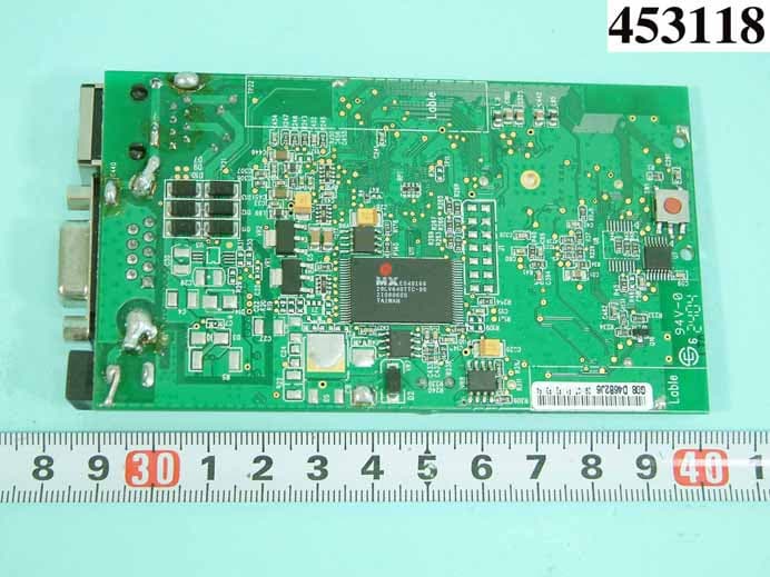
Click to zoom
Application Details
- Equipment Class
- NII - Unlicensed National Information Infrastructure TX
- Date of Grant
- Aug 18, 2004
- Application Purpose
- Original Equipment
- Date of Application
- Aug 18, 2004
- Equipment Note
- 11a/b/g Wireless Workgroup Bridge
- Frequency Range
- 5725.00000000 - 5825.00000000
- Company
- Hewlett Packard Enterprise
- Country
- United States
Documents & Files
Document Text
Text extracted from the exhibit documents filed with the FCC. Open a document above to read the original.
Users Manual
Quick Start Guide 11a/b/g Wireless Workgroup Bridge 3CRWE675075 The 3Com 11a/b/g Wireless Workgroup Bridge combines high-performance, interoperability, and ease- of-use to join isolated wired networks into a cohesive wireless local area network (WLAN). Instead of traveling over wires, data is transmitted across the WLAN using radio waves. The 3Com 11a/b/g Wireless Workgroup Bridge includes a robust suite of standards-based security features, and supports wireless network standards including 802.11a and 802.11g. For a complete list of the Bridge’s features, see the 3Com 11 a/b/g Wireless Workgroup Bridge User Guide located on the 3Com Installation CD. This Quick Start Guide describes the basic installation of the Bridge. It covers the following topics: ■Unpacking the Bridge ■Deciding Where to Place the Bridge ■Connecting the Bridge ■Checking the LED Indicators ■Attaching An External Antenna ■Determining if you Need to Configure the Bridge ■Using the 3Com Installation CD For complete instructions on using the Bridge, see the 3Com 11 a/b/g Wireless Workgroup Bridge User Guide located on the 3Com Installation CD. 11a/b/g Wireless Workgroup Bridge Power Port Serial Port Ethernet Port Cradle Observing Safety Precautions This equipment must be installed in compliance with local and national building codes, regulatory restrictions, and FCC rules. For the safety of people and equipment, only professional network personnel should install the Bridge. 1Unpacking the Bridge Make sure that you have the following items, which are included with the Bridge: ■Power adapter and power cord. ■Standard Category 5 unshielded twisted pair (UTP) Ethernet cable. ■Locking bar (used for securing a wall-mounted installation). ■Rubber feet (four; used for a flat-surface installation). ■3Com Installation CD. 2Deciding Where to Place the Bridge Place the Bridge in a dry, clean location near the hub, computer, or printer that will be connected to the Bridge. The location must have a power source and be within the following distance of a Wi-Fi- compliant wireless LAN access point or ad hoc wireless station: ■For 802.11a compatibility, place the Bridge within 50 m (164 ft) of a Wi-Fi compliant wireless LAN access point. ■For 802.11b/g compatibility, place the Bridge within 100 m (300 ft) of a Wi-Fi compliant wireless LAN access point. The location should be away from transformers, heavy-duty motors, fluorescent lights, microwave ovens, refrigerators, or other equipment that could cause radio signal interference. WARNING: To comply with FCC radio frequency (RF) exposure limits, a minimum body-to- antenna distance of 20 cm (8 in.) must be maintained when the Bridge is operational. WARNING: To avoid possible injury or damage to equipment, you must use either the provided power supply or power supply equipment that is safety certified according to UL, CSA, IEC, or other applicable national or international safety requirements for the country of use. All references to power supply in this document refer to equipment meeting these requirements. CAUTION: The 3Com power supply (part number 61-0107-000) input relies on a 16A rated building fuse or circuit protector for short circuit protection of the line to neutral conductors. Wall-mounting the Bridge The Bridge comes equipped with a cradle for mounting on a wall. For additional security, the Bridge also comes with a locking bar, which can be used with a security lock (not provided) to lock the Bridge to the cradle after the Bridge is mounted to the wall. To wall-mount the Bridge: 1Screw the cradle to a wall. 2Route the power and Ethernet cables through the large opening in the cradle. The figures below show the cradle being mounted to a wall, and then a cable being routed through the large opening in the cradle. 3Connect the power and Ethernet cables to the ports on the front of the Bridge. 4Snap the Bridge onto the cradle. To install the locking bar, push the locking bar through the opening in the side of the cradle until the hole on the locking bar is exposed. Insert a lock (not provided) through the hole on the locking bar, and then close the lock to secure it in place. See the user guide for detailed instructions. Placing the Bridge on a Flat Surface To install the Bridge on a flat surface such as a table or desktop, remove the backing from the four rubber feet and attach them on the bottom of the cradle. CAUTION: Do not place the Bridge on any type of metal surface. Select a location that is clear of obstructions and provides good reception. Wall-mounting the cradle Routing a cable Cradle Inserting the locking bar Securing the bar with a lock .11g .100 .10 .11a .11g .100 .10 .11a 3Connecting the Bridge Before connecting the Bridge to an Ethernet client, connect the power supply. The figure below shows the ports for connecting the power and Ethernet cables. The bridge can also be connected to a serial device. Serial cables come with a variety of connector sizes. If your connector is large and prevents the cradle from being attached to the Bridge, remove the end cap on the cradle. This allows the connector to extend through the cradle. Connecting to an Ethernet Device The Bridge is designed to be connected to an Ethernet client device such as a hub, computer, or printer. Connecting to a Hub You can supply network connections for up to 16 devices, such as computers and network printers, by connecting the Bridge to an Ethernet hub, as shown below. CAUTION: To avoid the possibility of a transmission loop situation between the Bridge and an access point, which could disrupt network operation, do not connect a Bridge that is set in Wireless Client (Infrastructure) mode directly to the LAN (for example, through a wall port or through a hub that is connected directly to the LAN). Power Cable Ethernet Cable . 1 1 g . 1 0 0 . 1 0 . 1 1 a Hub 11a/b/g Wireless Workgroup Brid ge Uplink Port Access Point P O W E R P O W E R ET H E R NE T E T H E R N E T W IR E LES S W I R E L E S S Connec…
Text truncated - open the document above for the full version.
Cover Letter(s)
Request Letter Subject: Limited Module Approval Date: 12 August 2004 FCC ID: O9C-WL560 Dear Reviewer, We, Sporton International Inc., are authorized by 3Com Corporation to have their state-of-the-art 802.11 a/b/g Workgroup Bridge approved under limited module approval authorization. The application of this module is specified to Mobile host equipment such as access point. The requirements regulated in Public Notice DA00-1407 have been fulfilled and clearly explained below. 1. The requirement of RF shielding: The shielding of the radio portion can be demonstrated in exhibition External Photo. 2. The requirement of buffered inputs: Buffered data inputs stage has been integrated in chip AR2313. 3. The requirement of power supply regulation: The part number of the power regulator is MP1410ES. 4. The requirements of section 15.203 and 15.204(C): The requirements of antenna connector and spurious emission have been fulfilled. Please reference the exhibition Test Report. 5. The requirement of stand-alone test configuration: Please reference exhibition Test Configuration Photo for the stand-alone test configuration. 6. The requirement of labeling: The instruction on the labeling rule of the end product has been stated in the users manual of this module. Please also see the exhibition Label Sample. 7. The requirement of compliance on specific rule or operating requirements: The required FCC rule has been fulfilled and all the instructions for maintaining compliance has been clearly stated in the Users Manual. 8. The requirement of RF exposure: Please refer exhibition RF Exposure for the compliance of RF exposure rule. Please do not hesitate to contact me for any questions of this request letter. Thank you. Regards, Dr. Alan Lane V. General Manager No. 52, Hwa Ya 1 st Rd., Hwa Ya Technology Park, Kwei-Shan Hsiang, TaoYuan Hsien, Taiwan, R.O.C. Sporton International Inc. e-mail: [email protected] Tel: +886 3 327 3456 Fax: +886 3 327 0973
Cover Letter(s)
3Com Corporation 350 Campus Drive, Marlborough, MA 01752 Tel: +1 508-323-5000 Fax: +1 508-323-1111 Colin Smith Regulatory Affairs & Approvals E-mail: [email protected] August 10, 2004 Federal Communications Commission Authorization and Evaluation Division FCC ID: O9C-WL560 Confidentiality Request Pursuant to Sections 0.457 and 0.459 of the Commission’s Rules, the Applicant hereby requests confidential treatment of information accompanying this Application, as outlined below: 1. Block Diagram 2. Circuit Diagram 3. Operational Description The above materials contain trade secrets and proprietary information not customarily released to the public. The public disclosure of these matters might be harmful to the Applicant and provide unjustified benefits to its competitors. The Applicant understands that pursuant to Rule 0.457, disclosure of this Application and all accompanying documentation will not be made before the date of the Grant for this application Yours sincerely, Colin Smith Regulator y Affairs & Approvals Tel: +1 408 326 5274 Fax: +1 408 326 5854 Email: [email protected]
Cover Letter(s)
MessageFrom: Linda Lin (???) [[email protected]] Sent: Wednesday, August 18, 2004 3:56 PM To: [email protected] Cc: Alan Lane (???) Subject: RE: 3COM 802.11abg project O9C-WL560 Dear Bill, 1. The whole mainboard is under " Limited Modular Approval", not only the circuit card. 2. Uploaded TSup. 3. No, the 2.4GHz 802.11b/g channels, and 5GHz 802.11a channels are not simultaneous transmission. 4. Uploaded. 5. The "Turbo” mode was tested for power and radiated emissions showed test result on report P. 25 and P. 79-83 TestRpt 802.11a Regards, Linda
External Photos
REPORT NO. : F453118 SPORTON International Inc. PAGE NUMBER : A1 OF A10 TEL : 886-2-2696-2468 ISSUED DATE : Aug. 05, 2004 FAX : 886-2-2696-2255 REPORT NO. : F453118 SPORTON International Inc. PAGE NUMBER : A2 OF A10 TEL : 886-2-2696-2468 ISSUED DATE : Aug. 05, 2004 FAX : 886-2-2696-2255 REPORT NO. : F453118 SPORTON International Inc. PAGE NUMBER : A3 OF A10 TEL : 886-2-2696-2468 ISSUED DATE : Aug. 05, 2004 FAX : 886-2-2696-2255 REPORT NO. : F453118 SPORTON International Inc. PAGE NUMBER : A4 OF A10 TEL : 886-2-2696-2468 ISSUED DATE : Aug. 05, 2004 FAX : 886-2-2696-2255 REPORT NO. : F453118 SPORTON International Inc. PAGE NUMBER : A5 OF A10 TEL : 886-2-2696-2468 ISSUED DATE : Aug. 05, 2004 FAX : 886-2-2696-2255 REPORT NO. : F453118 SPORTON International Inc. PAGE NUMBER : A6 OF A10 TEL : 886-2-2696-2468 ISSUED DATE : Aug. 05, 2004 FAX : 886-2-2696-2255 REPORT NO. : F453118 SPORTON International Inc. PAGE NUMBER : A7 OF A10 TEL : 886-2-2696-2468 ISSUED DATE : Aug. 05, 2004 FAX : 886-2-2696-2255 REPORT NO. : F453118 SPORTON International Inc. PAGE NUMBER : A8 OF A10 TEL : 886-2-2696-2468 ISSUED DATE : Aug. 05, 2004 FAX : 886-2-2696-2255 REPORT NO. : F453118 SPORTON International Inc. PAGE NUMBER : A9 OF A10 TEL : 886-2-2696-2468 ISSUED DATE : Aug. 05, 2004 FAX : 886-2-2696-2255 REPORT NO. : F453118 SPORTON International Inc. PAGE NUMBER : A10 OF A10 TEL : 886-2-2696-2468 ISSUED DATE : Aug. 05, 2004 FAX : 886-2-2696-2255
ID Label/Location Info
FCC ID: O9C-WL560 Label Location
Internal Photos
REPORT NO. : F453118 SPORTON International Inc. PAGE NUMBER : A1 OF A10 TEL : 886-2-2696-2468 ISSUED DATE : Aug. 05, 2004 FAX : 886-2-2696-2255 REPORT NO. : F453118 SPORTON International Inc. PAGE NUMBER : A2 OF A10 TEL : 886-2-2696-2468 ISSUED DATE : Aug. 05, 2004 FAX : 886-2-2696-2255 REPORT NO. : F453118 SPORTON International Inc. PAGE NUMBER : A3 OF A10 TEL : 886-2-2696-2468 ISSUED DATE : Aug. 05, 2004 FAX : 886-2-2696-2255 REPORT NO. : F453118 SPORTON International Inc. PAGE NUMBER : A4 OF A10 TEL : 886-2-2696-2468 ISSUED DATE : Aug. 05, 2004 FAX : 886-2-2696-2255 REPORT NO. : F453118 SPORTON International Inc. PAGE NUMBER : A5 OF A10 TEL : 886-2-2696-2468 ISSUED DATE : Aug. 05, 2004 FAX : 886-2-2696-2255 REPORT NO. : F453118 SPORTON International Inc. PAGE NUMBER : A6 OF A10 TEL : 886-2-2696-2468 ISSUED DATE : Aug. 05, 2004 FAX : 886-2-2696-2255 REPORT NO. : F453118 SPORTON International Inc. PAGE NUMBER : A7 OF A10 TEL : 886-2-2696-2468 ISSUED DATE : Aug. 05, 2004 FAX : 886-2-2696-2255 REPORT NO. : F453118 SPORTON International Inc. PAGE NUMBER : A8 OF A10 TEL : 886-2-2696-2468 ISSUED DATE : Aug. 05, 2004 FAX : 886-2-2696-2255 REPORT NO. : F453118 SPORTON International Inc. PAGE NUMBER : A9 OF A10 TEL : 886-2-2696-2468 ISSUED DATE : Aug. 05, 2004 FAX : 886-2-2696-2255 REPORT NO. : F453118 SPORTON International Inc. PAGE NUMBER : A10 OF A10 TEL : 886-2-2696-2468 ISSUED DATE : Aug. 05, 2004 FAX : 886-2-2696-2255
RF Exposure Info
FCC ID: O9C-WL560 Issued on Aug. 05, 2004 Report No.: F453118 SPORTON International Inc. Page No. : 112 of 116 TEL : 886-2-2696-2468 Issued Date : Aug. 05, 2004 FAX : 886-2-2696-2255 5.10. RF Exposure 5.10.1. Limit For Maximum Permissible Exposure (MPE) This product can be classified as mobile device, so the 20cm separation distance warning is required. In this section, the power density at 20cm location is calculated to examine if it is lower than the limit. (A) Limits for Occupational / Controlled Exposure Frequency Range (MHz) Electric Field Strength (E) (V/m) Magnetic Field Strength (H) (A/m) Power Density (S) (mW/ cm²) Averaging Time |E|²,|H|² or S (minutes) 0.3-3.0 614 1.63 (100)* 6 3.0-30 1842 / f 4.89 / f (900 / f)* 6 30-300 61.4 0.163 1.0 6 300-1500 F/300 6 1500-100,000 5 6 (B) Limits for General Population / Uncontrolled Exposure Frequency Range (MHz) Electric Field Strength (E) (V/m) Magnetic Field Strength (H) (A/m) Power Density (S) (mW/cm²) Averaging Time |E|²,|H|² or S ( minutes ) 0.3-1.34 614 1.63 (100)* 30 1.34-30 824/f 2.19/f (180/f)* 30 30-300 27.5 0.073 0.2 30 300-1500 F/1500 30 1500-100,000 1.0 30 F = frequency in MHz *Plane-wave equivalent power density FCC ID: O9C-WL560 Issued on Aug. 05, 2004 Report No.: F453118 SPORTON International Inc. Page No. : 113 of 116 TEL : 886-2-2696-2468 Issued Date : Aug. 05, 2004 FAX : 886-2-2696-2255 5.10.2. MPE Calculation Method E (V/m) = d GP××30 Power Density: Pd (mW/cm²) = 377 2 E E = Electric field (V/m) P = Peak RF output power (mW) G = EUT Antenna numeric gain (numeric) d = Separation distance between radiator and human body (m) The formula can be changed to Pd = 2 377 30 d GP × ×× From the peak EUT RF output power, the minimum mobile separation distance, d=2.5cm, as well as the gain of the used antenna, the RF power density can be obtained. FCC ID: O9C-WL560 Issued on Aug. 05, 2004 Report No.: F453118 SPORTON International Inc. Page No. : 114 of 116 TEL : 886-2-2696-2468 Issued Date : Aug. 05, 2004 FAX : 886-2-2696-2255 5.10.3. Calculated Result and Limit Only the mode with maximum Gain was calculated ( Mode 1 ). Normal Mode Channel No. Antenna Gain (dBi) Antenna Gain (numeric) Peak Output Power (dBm) Peak Output Power ( mW ) Power Density (S) (mW/cm²) Limit of Power Density (S) (mW/cm²) Channel 22 5 3.16 23.65 231.7395 0.1459 1 Turbo Mode Channel No. Antenna Gain (dBi) Antenna Gain (numeric) Peak Output Power (dBm) Peak Output Power ( mW ) Power Density (S) (mW/cm²) Limit of Power Density (S) (mW/cm²) Channel 03 5 3.16 18.5000 70.7946 0.0446 1
Test Report
FCC ID: O9C-WL560 Issued on Aug. 05, 2004 Report No.: F453118 SPORTON International Inc. TEL : 886-2-2696-2468 FAX : 886-2-2696-2255 FCC TEST REPORT CATEGORY : Module for Professional Use Mobile Host PRODUCT NAME : 802.11a/g Workgroup Bridge FCC ID. : O9C-WL560 FILING TYPE : Certification BRAND NAME : 3COM MODEL NAME : WL-560 APPLICANT : 3Com Corporation 5500 Great America Pkwy Santa Clara, CA. 95052 USA MANUFACTURER : DONGGUAN G-COM COMPUTER CO., LTD. 1 st Row Yin Shan Rd., Yin Hwu Industrial Area, Qingxi Town, Dong Guan City, Guang Dong, China ISSUED BY : SPORTON INTERNATIONAL INC. 6F, No. 106, Sec. 1, Hsin Tai Wu Rd., His Chih, Taipei Hsien, Taiwan, R.O.C. Statements: Only the test result of 802.11a part is shown in this test report. The test result in this report refers exclusively to the presented test model / sample. Without written approval of SPORTON International Inc., the test report shall not be reproduced except in full. Certificate or Test Report could not be used by the applicant to claim the product endorsement by CNLA, NVLAP or any agency of U.S. government. The test equipment used to perform the test are calibrated and traceable to NML/ROC or NIST/USA. Lab Code: 200079-0 FCC ID: O9C-WL560 Issued on Aug. 05, 2004 Report No.: F453118 SPORTON International Inc. Page No. : i TEL : 886-2-2696-2468 Issued Date : Aug. 05, 2004 FAX : 886-2-2696-2255 Table of Contents History of this test report....................................................................................................................................ii 1. General Description of Equipment under Test.............................................................................................1 1.1. Applicant..........................................................................................................................................................................................1 1.2. Manufacturer ...................................................................................................................................................................................1 1.3. Basic Description of Equipment under Test ....................................................................................................................................1 1.4. Features of Equipment under Test..................................................................................................................................................1 1.5. Antenna Description ........................................................................................................................................................................2 1.6. Table for Carrier Frequencies .........................................................................................................................................................3 2. Test Configuration of the Equipment under Test.........................................................................................4 2.1. Description of the Test ....................................................................................................................................................................4 2.2. Frequency Range Investigated .......................................................................................................................................................4 2.3. Description of Test Supporting Units...............................................................................................................................................5 2.4. Connection Diagram of Test System ..............................................................................................................................................5 2.5. Test Software ..................................................................................................................................................................................6 3. Test Location and Standards .........................................................................................................................7 3.1. Test Location...................................................................................................................................................................................7 3.2. Test Conditions ...............................................................................................................................................................................7 3.3. Standards for Methods of Measurement .........................................................................................................................................7 3.4. DoC Statement................................................................................................................................................................................7 4. List of Measurements......................................................................................................................................8 4.1. Summary of the Test Results ..........................................................................................................................................................8 5. Test Result .......................................................................................................................................................9 5.1. Test of 26dB Bandwidth ..................................................................................................................................................................9 5.2. Test of Maximum Peak Transmit Power .......................................................................................................................................19 5.3. Test of Peak Power Spectral Density............................................................................................................................................29 5.4. Test of the Ratio of Peak Excursion .................…
Text truncated - open the document above for the full version.
Test Report
FCC ID: O9C-WL560 Issued on Aug. 05, 2004 Report No.: F453118 SPORTON International Inc. Page No. : 93 of 116 TEL : 886-2-2696-2468 Issued Date : Aug. 05, 2004 FAX : 886-2-2696-2255 Turbo Mode Test Mode Mode 3 CH04 Temperature 26 deg. C Freq. Range 1GHz~40GHz Humidity 64% Tested By Steve Chen (A) Polarization: Horizontal (B) Polarization: Vertical Remark: Spurious on higher frequency band, the emission emitted by the EUT is too low to be measured. FCC ID: O9C-WL560 Issued on Aug. 05, 2004 Report No.: F453118 SPORTON International Inc. Page No. : 94 of 116 TEL : 886-2-2696-2468 Issued Date : Aug. 05, 2004 FAX : 886-2-2696-2255 Turbo Mode Test Mode Mode 3 CH05 Temperature 26 deg. C Freq. Range 1GHz~40GHz Humidity 64% Tested By Steve Chen (A) Polarization: Horizontal (B) Polarization: Vertical Remark: Spurious on higher frequency band, the emission emitted by the EUT is too low to be measured. FCC ID: O9C-WL560 Issued on Aug. 05, 2004 Report No.: F453118 SPORTON International Inc. Page No. : 95 of 116 TEL : 886-2-2696-2468 Issued Date : Aug. 05, 2004 FAX : 886-2-2696-2255 5.6.6. Photographs of Radiated Emission Test Configuration z The photographs show the configuration that generates the maximum emission. Mode 1 FRONT VIEW REAR VIEW FCC ID: O9C-WL560 Issued on Aug. 05, 2004 Report No.: F453118 SPORTON International Inc. Page No. : 96 of 116 TEL : 886-2-2696-2468 Issued Date : Aug. 05, 2004 FAX : 886-2-2696-2255 Mode 2 FRONT VIEW REAR VIEW FCC ID: O9C-WL560 Issued on Aug. 05, 2004 Report No.: F453118 SPORTON International Inc. Page No. : 97 of 116 TEL : 886-2-2696-2468 Issued Date : Aug. 05, 2004 FAX : 886-2-2696-2255 Mode 3 FRONT VIEW REAR VIEW FCC ID: O9C-WL560 Issued on Aug. 05, 2004 Report No.: F453118 SPORTON International Inc. Page No. : 98 of 116 TEL : 886-2-2696-2468 Issued Date : Aug. 05, 2004 FAX : 886-2-2696-2255 5.7. Test of Frequency Stability 5.7.1. Measuring Instruments Item 9 of the table on section 6. 5.7.2. Test Procedures 1. The transmitter output is connected to the spectrum analyzer through an attenuator. 2. Set RBW of spectrum analyzer to 10kHz and VBW to 10kHz. 3. Use peak detector mode, Max-hold and search the peak of trace 1. 4. The test extreme voltage is, according to 2.1055(d)(1), is to change the primary supply voltage from 85 to 115 percent of the nominal value 5. Extreme temperature rule is, according to 2.1055(a)(1), -30°C~50°C . 5.7.3. Test Setup Layout Spectrum analyzer Oven FCC ID: O9C-WL560 Issued on Aug. 05, 2004 Report No.: F453118 SPORTON International Inc. Page No. : 99 of 116 TEL : 886-2-2696-2468 Issued Date : Aug. 05, 2004 FAX : 886-2-2696-2255 5.7.4. Test Result : See spectrum analyzer plots below Modulation Type: Un-Modulated Carrier (CW) Temperature: 25°C Relative Humidity: 62 % Duty cycle of the equipment during the test: 100% Temperature vs. Frequency Stability Temperature Measurement Frequency (MHz) ( °C ) 5240.00 5320.00 5805 -30 5240.0160 5320.0056 5805.0015 -20 5240.0220 5320.0021 5805.0045 -10 5240.0010 5320.0044 5805.0044 0 5239.9960 5320.0024 5805.0023 10 5239.9520 5320.0027 5805.0047 20 5239.9260 5320.0014 5805.0064 30 5239.9450 5320.0012 5805.0021 40 5239.9400 5320.0022 5805.0014 50 5239.9460 5320.0047 5805.0002 Max. Deviation (MHz) 5240.0160 5320.0056 5805.0015 Max. Deviation (ppm) 3.05 1.05 0.26 FCC ID: O9C-WL560 Issued on Aug. 05, 2004 Report No.: F453118 SPORTON International Inc. Page No. : 100 of 116 TEL : 886-2-2696-2468 Issued Date : Aug. 05, 2004 FAX : 886-2-2696-2255 Voltage vs. Frequency Stability Voltage Measurement Frequency (MHz) ( V ) 5240.00 5320.00 5805 126.50 5240.0130 5320.0100 5805.0070 110.00 5240.0130 5320.0080 5805.0080 93.50 5240.0150 5320.0078 5805.0065 Max. Deviation (MHz) 5240.0150 5320.0100 5805.0070 Max. Deviation (ppm) 2.86 1.88 1.21 FCC ID: O9C-WL560 Issued on Aug. 05, 2004 Report No.: F453118 SPORTON International Inc. Page No. : 101 of 116 TEL : 886-2-2696-2468 Issued Date : Aug. 05, 2004 FAX : 886-2-2696-2255 5.8. Test of AC Power Line Conducted Emission 5.8.1. Measuring Instruments Please reference item 1~7 in chapter 6 for the instruments used for testing. 5.8.2. Test Procedures 1. Configure the EUT according to ANSI C63.4. 2. The EUT has to be placed 0.4 meter far from the conducting wall of the shielding room and at least 80 centimeters from any other grounded conducting surface. 3. Connect EUT to the power mains through a line impedance stabilization network (LISN). 4. All the support units are connected to the other LISNs. The LISN should provides 50uH/50ohms coupling impedance. 5. The frequency range from 150 KHz to 30 MHz was searched. 6. Use the Channel & Power Controlling software to make the EUT working on selected channel and expected output power, then use the “H” Patter Generator software to make the supporting equipments stay on working condition. 7. Set the test-receiver system to Peak Detect Function and Specified Bandwidth with Maximum Hold Mode. 8. The measurement has to be done between each power line and ground at the power terminal for each RF channel. Only one RF channel has to be investigated since this test is independent with the RF channel selection. FCC ID: O9C-WL560 Issued on Aug. 05, 2004 Report No.: F453118 SPORTON International Inc. Page No. : 102 of 116 TEL : 886-2-2696-2468 Issued Date : Aug. 05, 2004 FAX : 886-2-2696-2255 5.8.3. Test Result of Conducted Emission Test Mode Mode 1 Temperature / Humidity 25 deg. C / 60% Tested By Jason Chang Line to Ground Neutral to Ground FCC ID: O9C-WL560 Issued on Aug. 05, 2004 Report No.: F453118 SPORTON International Inc. Page No. : 103 of 116 TEL : 886-2-2696-2468 Issued Date : Aug. 05, 2004 FAX : 886-2-2696-2255 Test Mode Mode 2 Temperature / Humidity 25 deg. C / 60% Tested By Jason Chang Line to Ground Neutral to Ground FCC ID: O9C-WL560 Issued on Aug. 05, 2004 Report No.: F453118 SPORTON International Inc. Page No. : 104 of 116 TEL : 886-2-2696-2468 Issued Date : Aug. 05, 2004 FAX : 886-2-2696-2255 Test Mode Mode 3 Tem…
Text truncated - open the document above for the full version.
Contact Information
Applicant
Jim Taylor(Manager, Hardware Support Engineering)
Technical Contact
Sporton International Inc.Alan Lane
[email protected]+886 6 327 3456
No 52, Hwa Ya First Rd · Kwei-Shan Hsiang, Taoyuan · Taiwan
Test Firm
SPORTON International IncKathy Lin
Technical Specifications
| # | Rule Parts | Frequency Range | Power Output |
|---|---|---|---|
| 3 | 15E | 5.72 GHz - 5.83 GHz | 232.00 mW |
Other Applications from Hewlett Packard Enterprise

O9C-BJNGABB0038
Oct 29, 2015HPE MSR954-W 1GbE+SFP LTE (AM) Rtr
Equipment Class
DTS - Digital Transmission System
O9C-BJNGAFB0008
Jul 30, 2015Wireless LAN Access Point
Equipment Class
JBP - Part 15 Class B Computing Device Peripheral
O9C-BJNGAFB0005
Nov 06, 2014Unified Wired-WLAN Walljack
Equipment Class
JBP - Part 15 Class B Computing Device Peripheral
O9C-BJNGAFB0004
Sep 04, 2014Wireless LAN Access Point
Equipment Class
JBP - Part 15 Class B Computing Device Peripheral
O9C-BJNGAFB0003
Jul 02, 2014Unified Wired-WLAN Walljack
Equipment Class
DTS - Digital Transmission System