O9CWL464Bridging kit - 802.11a
Hewlett Packard Enterprise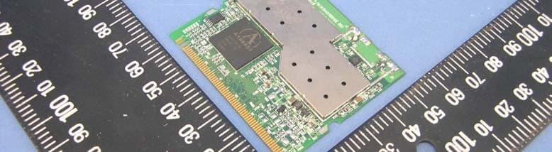
Click to zoom
Application Details
- Equipment Class
- DTS - Digital Transmission System
- Date of Grant
- Jul 13, 2005
- Application Purpose
- Original Equipment
- Date of Application
- Jul 13, 2005
- Equipment Note
- Bridging kit - 802.11a
- Frequency Range
- 5725.00000000 - 5850.00000000
- Company
- Hewlett Packard Enterprise
- Country
- United States
Documents & Files
Document Text
Text extracted from the exhibit documents filed with the FCC. Open a document above to read the original.
Users Manual
802.11a mini-PCI Radio Module MODEL WL-464 The 3Com 802.11a mini-PCI Radio Module Kit contains everything you need to install an additional radio and antenna into your 3Com Access Point. Kit Contents The upgrade kit contains these items: • One antenna module • One 802.11a mini-PCI Radio Module • Two cables connect the antenna module and mini PCI card by direct soldering. 1 Detach and disconnect the access point If the access point is mounted on the wall, turn the unit counterclockwise to disengage it from the mounting plate. Disconnect the Ethernet cable. Place the access point face down on a static-free surface. 2 Remove the back cover Using a cross-tip screwdriver, remove the four screws from the back cover. Remove the cover from the unit. Set the cover and screws aside. 3 Remove the antenna housing. Grasp the inside edge of the antenna housing and pull up to disengage the housing from the unit, as shown below. This part is no longer needed. 4 Install the 11a upgrade kit. 4.1. 11a mini PCI card side: Holding the radio board at an angle, align the contact edge with the mini PCI connector on the unit. Make sure the keying notch on the contact edge line up with the key on the connector, as shown in the detail below. Slide the board into the connector and press down gently until the two retainer clips snap into place. 4.2. Antenna module side: 1 Align the antenna module with the snaps and posts on the unit and press until the module snaps firmly into place. 2 Align the cables to be routed through the slots in the unit. 3 After the cables are aligned, press them down out of the way inside the housing. 5 Replace the back cover. Make sure that the cables are tucked away inside the housing so that they do not obstruct the cover. Align the back cover with the unit and settle the cover into place. Tighten the four screw. 6 Attach the antennas. Being careful not to touch the antenna tips, screw the antennas onto the SMA connectors and hand tighten them. After network startup , you may need to adjust the antennas to fine tune radio coverage. 7 Reinstall the access point. Reconnect the Ethernet cable and reattach the access point to the wall mounting plate. Adjust the antennas to improve the radio signal, if necessary. SELECTING AND CONNECTING A DIFFERENT ANTENNA MODEL The standard detachable antennas supplied with the WL-464 11a mini-PCI radio module and are suitable for a broad variety of environments. If you require a different type of antenna several options are available by model number from the 3Com Web site(www.3Com.ccom ). For each of the antenna models, you will need either a 6-foot accessory cable (model 3CWE480), a 20-foot accessory cable (model 3CWE481), or a 50-foot accessory cable (model 3CWE482) to provide the transition from the SMA connector on the access point to the N-type connector on the antenna. To ensure the physical safety of anyone near the antenna and to prevent damage to the access point, follow the building code for antenna installations in your area. Also, when connecting the optional antenna to the access point, remember to use only the A-side connector on the access point, on the right when properly installed. B-side install a terminator at the same time. 1 Position the antenna so that there are minimal obstacles between it and any client with which it will communicate. While maintaining a direct line of sight between the antenna and a client is not strictly necessary, such an arrangement helps to ensure a strong signal. Ensure that access is available for routing the antenna cable from the antenna to the access point. 2 If they are installed, remove both arms of standard detachable antenna, making sure not to handle the tips of antenna. 3 Connect one end of the optional antenna cable to the antenna and secure the antenna in place. 4 Connect the free end of the antenna cable to the right-hand side connection on the access point, as shown in the illustration above. 5 Make certain that the antennas and antenna masts are appropriately ground to prevent injury or damage from lightning strikes. Regulatory Compliance Information 3Com 802.11a Wireless LAN Access Point Upgrade Kit Federal Communication Commission Interference Statement This equipment has been tested and found to comply with the limits for a Class B digital device, pursuant to Part 15 of the FCC Rules. These limits are designed to provide reasonable protection against harmful interference in a residential installation. This equipment generates, uses and can radiate radio frequency energy and, if not installed and used in accordance with the instructions, may cause harmful interference to radio communications. However, there is no guarantee that interference will not occur in a particular installation. If this equipment does cause harmful interference to radio or television reception, which can be determined by turning the equipment off and on, the user is encouraged to try to correct the interference by one of the following measures: - Reorient or relocate the receiving antenna. - Increase the separation between the equipment and receiver. - Connect the equipment into an outlet on a circuit different from that to which the receiver is connected. - Consult the dealer or an experienced radio/TV technician for help. This device complies with Part 15 of the FCC Rules. Operation is subject to the following two conditions: (1) This device may not cause harmful interference, and (2) this device must accept any interference received, including interference that may cause undesired operation. FCC Caution: Any changes or modifications not expressly approved by the party responsible for compliance could void the user's authority to operate this equipment. IMPORTANT NOTE: FCC Radiation Exposure Statement: This equipment complies with FCC radiation exposure limits set forth for an uncontrolled environment. This equipment should be installed and operated with minimum distance 30cm between the radiator & your body. This tran…
Text truncated - open the document above for the full version.
Cover Letter(s)
3Com Corporation 350 Campus Drive, Marlborough, MA 01752-3064, U.S.A. Federal Communications Commission Authorization and Evaluation Division Confidentiality Request FCC ID: O9CWL464 Pursuant to Sections 0.457 and 0.459 of the Commission’s Rules, the Applicant hereby requests confidential treatment of information accompanying this Application as outlined below: Schematics Block Diagram The above materials contain trade secrets and proprietary information not customarily released to the public. The public disclosure of these matters might be harmful to the Applicant and provide unjustified benefits to its competitors. The Applicant understands that pursuant to Rule 0.457, disclosure of this Application and all accompanying documentation will not be made before the date of the Grant for this application. Sincerely yours, ------------------------------------------------------------------------------ Stanley Lin / Senior Engineer 3Com Corporation TEL: (886) 2-8722-2645 FAX: (886) 2-8780-4821 [email protected]
Cover Letter(s)
FCC ID: O9CWL464 ADT No. 940326H02 Limited Modular Approval Request Letter Advance Data Technology June 18, 2005 Dear Application Examiner, 3Com Corporation’s Bridging kit - 802.11a, FCC ID: O9CWL464, would like to have your authorization as a modular approval specific to the mobile device such as Access Points. The requirements of Public Notice DA00-1407 have been met and shown on the following statements. 1. “The modular transmitter must have its own RF shielding.”: The radio portion of this module has been shielded, please see exhibition External Photo. 2. “The modular transmitter must have buffered modulation/data inputs.” The EUT has buffered data inputs, it is integrated in chip AR5212. 3. “The modular transmitter must have its own power supply regulation.” The chips RF converter which will influence the frequency radiation, have to be 2.5V DC powered. The mini-pci interface provides 3.3VDC, so there are regulators in front of these chips, the part number of this regulator is LTC3406ES5. 4. “The modular transmitter must comply with the antenna requirements of section 15.203 and 15.204(C).” The EUT meets the FCC antenna requirements. The spurious emission, unique antenna connector and photo of antennas are shown in the test report. 5. “The modular transmitter must be tested in a stand-alone configuration” The EUT was tested in a stand-alone configuration via a PCIMCIA adapter card. Please see section Photographs of Test Configuration in the test report. 6. “The modular transmitter must be labeled with its own FCC ID number.” Please see exhibition Label Sample for the FCC ID of this module. And also in the exhibition Users Manual, there are instructions give to the OEM on how to label the end product. FCC ID: O9CWL464 ADT No. 940326H02 7. “The modular transmitter must comply with any specific rule or operating requirements applicable to the transmitter and the manufacturer must provide adequate instructions along with the module to explain any such requirements.” The EUT is compliant with all applicable FCC rules. Detail instructions for maintaining compliance are given in the Users Manual. 8. “The modular transmitter must comply with any applicable RF exposure requirements.” The EUT is compliant with all applicable RF exposure requirements. RF Exposure is addressed in the RF exposure exhibition. Please contact me if you have any further questions. Thanks for your attention. Best Regards, Eric Lin Manager of Hsinchu Certification Service Div. Advance Data Technology
Cover Letter(s)
3Com Corporation 350 Campus Drive, Marlborough, MA 01752-3064, U.S.A. Power of Attorney To whom it may concern: We, the undersigned 3Com Corporation hereby authorize Advance Data Technology Corporation (ADT) of Taiwan to act on our behalf in all matters relating to all processes required in the FCC Part 15E approval and any communication needed with the national authority. Any and all acts carried out by ADT on our behalf shall have the same effects as acts of our own. If you have any questions regarding the authorization, please don’t hesitate to contact us. Thank you! Sincerely yours, ------------------------------------------------------------------------------- Stanley Lin / Senior Engineer 3Com Corporation TEL: (886) 2-8722-2645 FAX: (886) 2-8780-4821 [email protected]
External Photos
Page 1 CONSTRUCTION PHOTOS OF EUT Page 2 Page 3 Page 4 Page 5 Page 6 Model : 3CWE502 Page 7 Page 8 Model : 3CWE591 (Z1996) Page 9 Page 10 Page 11 Model : 3CWE598 (Z1997) Page 12 Page 13 Model : 3CWE596 Page 14 Page 15 Page 16
ID Label/Location Info
FCC ID: O9CWL464 FCC LABEL LOCATION The label will be permanently affixed at a conspicuous location on the device. Label
Internal Photos
Page 17 Page 18 Page 19 Page 20
Operational Description
FCC ID: O9CWL464 Repport No. RF940326H02 Technical Description This device is a Bridging kit - 802.11a operates in 5GHz with OFDM technique. The transmitter rate could be 1/2/5.5/6/9/11/12/18/24/36/48/54Mbps, and the maximum data rate could be up to 108Mbps in turbo mode. The transmitter of the EUT is powered by POE (Power over Ethernet). The antenna The antennas used in this product are as below: No.ModelAntnnna Type 2.4/ 5GHz Antenna Gain Connector Type 13CWE591 (Z1996) High gain omni antenna6/ 8 dBiN Female 23CWE598 (Z1997) Medium gain panel antenna8/ 10 dBiN Female 33CWE596High gain panel antenna18/ 20 dBiN Female Under normal use condition, the user has to keep at least 20 cm separation distance between radiator and the body of the user. For more detailed instruction, please refer to the user’s manual. FCC 15.407(c) states : The device shall automatically discontinue transmission in case of either absence of information to transmit or operational failure. These provisions are not intended to preclude the transmission of control or signaling information or the use of repetitive codes used by certain digital technologies to complete frame or burst intervals. Applicants shall include in their application for equipment authorization a description of hoe this requirement is met. Data transmission is always initiated by software, which is then pass down through the MAC, through the digital and analog baseband, and finally to the RF chip. Several special packets (ACKs, CTS, PSPoll, etc...) are initiated by the MAC. There are the only ways the digital baseband portion will turn on the RF transmitter, which it then turns off at the end of the packet. Therefore, the transmitter will be on only while one of the aforementioned packets are being transmitted.
RF Exposure Info
FCC ID: O9CWL464 Report No.: SA940326H021Issued: June 13, 2005 RF EXPOSURE REPORT REPORT NO.: SA940326H02 MODEL NO.: WL-464 ACCORDING: FCC Guidelines for Human Exposure IEEE C95.1 APPLICANT:3Com Corporation ADDRESS:350 Campus Drive, Marlborough, MA 01752- 3064, U.S.A. ISSUED BY:Advance Data Technology Corporation LAB LOCATION:No. 81-1, Lu Liao Keng, 9 Ling, Wu Lung Tsuen, Chiung Lin Hsiang, Hsin Chu Hsien, Taiwan, R.O.C. FCC ID: O9CWL464 Report No.: SA940326H022Issued: June 13, 2005 RF Exposure Measurement 1. Introduction In this document, we try to prove the safety of radiation harmfulness to the human body for our product. The limit for Maximum Permissible Exposure (MPE) specified in FCC 1.1310 is followed. The Gain of the antenna used in this product is measured in a Fully Anechoic Chamber (FAC) calibrated for antenna measurement in ADT, and also the maximum total power input to the antenna is measured. Through the Friis transmission formula and the maximum gain of the antenna, we can calculate the distance, away from the product, where the limit of MPE is reached. Although the Friis transmission formula is a far field assumption, the calculated result of that is an over-prediction for near field power density. We will take that as the worst case to specify the safety range. 2. RF Exposure Limit According to FCC 1.1310: The criteria listed in the following table shall be used to evaluate the environmental impact of human exposure to radio-frequency (RF) radiation as specified in 1.1307(b) LIMITS FOR MAXIMUM PERMISSIBLE EXPOSURE (MPE) Frequency Range (MHz) Electric Field Strength (V/m) Magnetic Field Strength (A/m) Power Density (mW/cm 2 ) Average Time (minutes) (A)Limits For Occupational / Control Exposures 300-1500......F/3006 1500-100,000......56 (B)Limits For General Population / Uncontrolled Exposure 300-1500......F/15006 1500-100,000......1.030 F = Frequency in MHz FCC ID: O9CWL464 Report No.: SA940326H023Issued: June 13, 2005 3. Friis Formula Friis transmission formula : Pd = (Pout*G) / (4*pi*r 2 ) where Pd = power density in mW/cm 2 Pout = output power to antenna in mW G = gain of antenna in linear scale Pi = 3.1416 R = distance between observation point and center of the radiator in cm Pd is the limit of MPE, 1 mW/cm 2 . If we know the maximum Gain of the antenna and the total power input to the antenna, through the calculation, we will know the MPE value at distance 20cm. Ref. : David K. Cheng, Field and Wave Electromagnetics, Second Edition, Page 640, Eq. (11-133). 4 EUT Operating condition The software provided by Manufacturer enabled the EUT to transmit and receive data at lowest, middle and highest channel individually. 5. Classification The antenna of this product, under normal use condition, is at least 30cm away from the body of the user. Warning statement to the user for keeping at least 30cm or more separation distance with the antenna should be included in users manual. So, this device is classified as Mobile Device FCC ID: O9CWL464 Report No.: SA940326H024Issued: June 13, 2005 6 Test Results 6.1 Antenna Gain Antenna 1: The maximum Gain of the antenna is 6.8dBi. Antenna 2: The maximum Gain of the antenna is 8.8dBi. Antenna 3: The maximum Gain of the antenna is 18.8dBi. Antenna 4: The maximum Gain of the antenna is 2.5dBi. No.ModelAntnnna Type 2.4/ 5GHz Antenna Gain Cable Loss 13CWE591 (Z1996)High gain omni antenna6/ 8 dBi1.2dB 23CWE598 (Z1997)Medium gain panel antenna 8/ 10 dBi1.2dB 33CWE596High gain panel antenna18/ 20 dBi1.2dB 43CWE502Small Omni (Rubber Duck)2.5/ 2.5 dBiNA Note: 1. Antenna 2 and 3 can only be used in point-to-point applications. FCC ID: O9CWL464 Report No.: SA940326H025Issued: June 13, 2005 6.2 Output Power Into Antenna & RF Exposure value at distance 30cm: Operated in 5150 ~ 5250MHz, 5250MHz ~ 5350MHz band: (15.407) Normal Mode : Antenna 1 Channel Channel Frequency (MHz) Output Power to Antenna (mW) Power Density (mW/cm 2 ) Limit of Power Density (mW/cm 2 ) 1518026.915348040.01139061.0 4524027.101916320.0114695561.0 55260143.87985780.0608900891.0 8532080.537844120.034083691.0 Turbo Mode : Antenna 1 Channel Channel Frequency (MHz) Output Power to Antenna (mW) Power Density (mW/cm 2 ) Limit of Power Density (mW/cm 2 ) 1521028.183829310.0119274231.0 2525029.376496520.0124321611.0 3529094.623716140.0400448441.0 Normal Mode : Antenna 2 Channel Channel Frequency (MHz) Output Power to Antenna (mW) Power Density (mW/cm 2 ) Limit of Power Density (mW/cm 2 ) 1518016.218100970.0108779391.0 4524016.557699630.0111057171.0 5526081.283051620.0545188411.0 8532071.121351370.0477031011.0 Turbo Mode : Antenna 2 Channel Channel Frequency (MHz) Output Power to Antenna (mW) Power Density (mW/cm 2 ) Limit of Power Density (mW/cm 2 ) 1521016.710906140.0112084771.0 2525018.450154190.012375041.0 3529075.85775750.0508799421.0 FCC ID: O9CWL464 Report No.: SA940326H026Issued: June 13, 2005 Normal Mode : Antenna 3 Channel Channel Frequency (MHz) Output Power to Antenna (mW) Power Density (mW/cm 2 ) Limit of Power Density (mW/cm 2 ) 151802.1877616240.0330163551.0 452402.0701413490.0312413021.0 5526010.665961210.1609641381.0 8532011.694993910.1764936681.0 Turbo Mode : Antenna 3 Channel Channel Frequency (MHz) Output Power to Antenna (mW) Power Density (mW/cm 2 ) Limit of Power Density (mW/cm 2 ) 152102.213094710.0333986671.0 252502.2490546060.0339413511.0 3529011.587773560.1748755641.0 Normal Mode : Antenna 4 Channel Channel Frequency (MHz) Output Power to Antenna (mW) Power Density (mW/cm 2 ) Limit of Power Density (mW/cm 2 ) 1518026.915348040.0042320091.0 4524027.101916320.0042613441.0 55260143.87985780.0226228131.0 8532080.537844120.0126632921.0 Turbo Mode : Antenna 4 Channel Channel Frequency (MHz) Output Power to Antenna (mW) Power Density (mW/cm 2 ) Limit of Power Density (mW/cm 2 ) 1521028.183829310.0044314581.0 2525029.376496520.0046189861.0 3529094.623716140.014878071.0 FCC ID: O9CWL464 Report No.: SA940326H027Issued: June 13, 2005 Operated in 5725 ~ 5850MHz band: (15.…
Text truncated - open the document above for the full version.
Test Report
FCC ID: O9CWL464 Report No.: RF940326H021Report Format Version 2.0.2 FCC TEST REPORT (15.247) REPORT NO.: RF940326H02 MODEL NO.: WL-464 RECEIVED: April 6, 2005 TESTED: April 13 to May 27, 2005 ISSUED: June 9, 2005 APPLICANT:3Com Corporation ADDRESS:350 Campus Drive, Marlborough, MA 01752-3064, U.S.A. ISSUED BY:Advance Data Technology Corporation TEST LOCATION:No. 81-1, Lu Liao Keng, 9 Ling, Wu Lung Tsuen, Chiung Lin Hsiang, Hsin Chu Hsien, Taiwan, R.O.C. This test report consists of 84 pages in total. It may be duplicated completely for legal use with the approval of the applicant. It should not be reproduced except in full, without the written approval of our laboratory. The client should not use it to claim product endorsement by CNLA, A2LA or any government agencies. The test results in the report only apply to the tested sample. The test results in this report are traceable to the national or international standards. 0536No. 2177-01 ILAC MRA FCC ID: O9CWL464 Report No.: RF940326H022Report Format Version 2.0.2 Table of Contents 1.CERTIFICATION.....................................................................................................5 2.SUMMARY OF TEST RESULTS.............................................................................6 3.GENERAL INFORMATION .....................................................................................7 3.1GENERAL DESCRIPTION OF EUT........................................................................7 3.2DESCRIPTION OF TEST MODES..........................................................................9 3.2.1 TEST MODE APPLICABILITY AND TESTED CHANNEL DETAIL:........................10 3.3GENERAL DESCRIPTION OF APPLIED STANDARDS .......................................12 3.4DESCRIPTION OF SUPPORT UNITS..................................................................13 3.5CONFIGURATION OF SYSTEM UNDER TEST...................................................14 4.TEST TYPES AND RESULTS (802.11a, 5725~5850MHz Band)...........................15 4.1CONDUCTED EMISSION MEASUREMENT........................................................15 4.1.1 LIMITS OF CONDUCTED EMISSION MEASUREMENT......................................15 4.1.2 TEST INSTRUMENTS ..........................................................................................15 4.1.3 TEST PROCEDURES ..........................................................................................16 4.1.4 DEVIATION FROM TEST STANDARD .................................................................16 4.1.5 TEST SETUP........................................................................................................17 4.1.6 EUT OPERATING CONDITIONS..........................................................................17 4.1.7 TEST RESULTS (MODE 1) ..................................................................................18 4.1.8 TEST RESULTS (MODE 2) ..................................................................................20 4.1.9 TEST RESULTS (MODE 3) ..................................................................................22 4.1.10 TEST RESULTS (MODE 4) ..................................................................................24 4.2RADIATED EMISSION MEASUREMENT .............................................................26 4.2.1 LIMITS OF RADIATED EMISSION MEASUREMENT ...........................................26 4.2.2 TEST INSTRUMENTS ..........................................................................................27 4.2.3 TEST PROCEDURES ..........................................................................................28 4.2.4 DEVIATION FROM TEST STANDARD .................................................................28 4.2.5 TEST SETUP........................................................................................................29 4.2.6 EUT OPERATING CONDITIONS..........................................................................29 4.2.7 TEST RESULTS (MODE 1) ..................................................................................30 4.2.8 TEST RESULTS (MODE 2) ..................................................................................35 4.2.9 TEST RESULTS (MODE 3) ..................................................................................40 4.2.10 TEST RESULTS (MODE 4) ..................................................................................45 FCC ID: O9CWL464 Report No.: RF940326H023Report Format Version 2.0.2 4.36DB BANDWIDTH MEASUREMENT....................................................................50 4.3.1 LIMITS OF 6DB BANDWIDTH MEASUREMENT .................................................50 4.3.2 TEST INSTRUMENTS ..........................................................................................50 4.3.3 TEST PROCEDURE.............................................................................................51 4.3.4 DEVIATION FROM TEST STANDARD .................................................................51 4.3.5 TEST SETUP........................................................................................................51 4.3.6 EUT OPERATING CONDITIONS..........................................................................51 4.3.7 TEST RESULTS ...................................................................................................52 4.4MAXIMUM PEAK OUTPUT POWER ....................................................................56 4.4.1 LIMITS OF MAXIMUM PEAK OUTPUT POWER MEASUREMENT .....................56 4.4.2 INSTRUMENTS....................................................................................................56 4.4.3 TEST PROCEDURES ..........................................................................................57 4.4.4 DEVIATION FROM TEST STANDARD .................................................................57 4.4.5 TEST SETUP..........................................................................................…
Text truncated - open the document above for the full version.
Test Report
FCC ID: O9CWL464 Report No.: RF940326H0262Report Format Version 2.0.2 4.5 POWER SPECTRAL DENSITY MEASUREMENT 4.5.1 LIMITS OF POWER SPECTRAL DENSITY MEASUREMENT The Maximum of Power Spectral Density Measurement is 8dBm. 4.5.2 TEST INSTRUMENTS Description & ManufacturerModel No.Serial No.Calibrated Until R&S SPECTRUM ANALYZERFSP40100036Nov. 23, 2005 NOTE: 1.The measurement uncertainty is less than +/- 2.6dB, which is calculated as per the NAMAS document NIS81. 2.The calibration interval of the above test instruments is 12 months and the calibrations are traceable to NML/ROC and NIST/USA. FCC ID: O9CWL464 Report No.: RF940326H0263Report Format Version 2.0.2 4.5.3 TEST PROCEDURE The transmitter output was connected to the spectrum analyzer through an attenuator, the bandwidth of the fundamental frequency was measured with the spectrum analyzer using 3 kHz RBW and 30 kHz VBW, set sweep time = span/3 kHz. The power spectral density was measured and recorded. The sweep time is allowed to be longer than span/3 kHz for a full response of the mixer in the spectrum analyzer. 4.5.4 DEVIATION FROM TEST STANDARD No deviation 4.5.5 TEST SETUP 4.5.6 EUT OPERATING CONDITION Same as Item 4.3.6 EUT SPECTRUM ANALYZER FCC ID: O9CWL464 Report No.: RF940326H0264Report Format Version 2.0.2 4.5.7 TEST RESULTS 802.11a OFDM modulation EUTBridging kit - 802.11aMODELWL-464 MODULATION TYPE BPSKTRANSFER RATE6Mbps INPUT POWER (SYSTEM) 120Vac, 60 Hz ENVIRONMENTAL CONDITIONS 27deg. C, 62%RH, 960 hPa TESTED BY Rex Huang CHANNEL CHANNEL FREQUENCY (MHz ) RF POWER LEVEL IN 3 kHz BW (dBm) MAXIMUM LIMIT (dBm) PASS/FAIL 15745-8.528PASS 55825-8.868PASS FCC ID: O9CWL464 Report No.: RF940326H0265Report Format Version 2.0.2 CH1 FCC ID: O9CWL464 Report No.: RF940326H0266Report Format Version 2.0.2 CH5 FCC ID: O9CWL464 Report No.: RF940326H0267Report Format Version 2.0.2 802.11a Turbo OFDM modulation EUTBridging kit - 802.11aMODELWL-464 MODULATION TYPE BPSKTRANSFER RATE6Mbps INPUT POWER (SYSTEM) 120Vac, 60 Hz ENVIRONMENTAL CONDITIONS 27deg. C, 62%RH, 960 hPa TESTED BY Rex Huang CHANNEL CHANNEL FREQUENCY (MHz ) RF POWER LEVEL IN 3 kHz BW (dBm) MAXIMUM LIMIT (dBm) PASS/FAIL 15760-9.98PASS 25800-10.88PASS FCC ID: O9CWL464 Report No.: RF940326H0268Report Format Version 2.0.2 CH1 FCC ID: O9CWL464 Report No.: RF940326H0269Report Format Version 2.0.2 CH2 FCC ID: O9CWL464 Report No.: RF940326H0270Report Format Version 2.0.2 4.6 BAND EDGES MEASUREMENT 4.6.1 LIMITS OF BAND EDGES MEASUREMENT Below –20dB of the highest emission level of operating band (in 100kHz Resolution Bandwidth). 4.6.2 TEST INSTRUMENTS Description & ManufacturerModel No.Serial No.Calibrated Until R&S SPECTRUM ANALYZERFSP40100036Nov. 23, 2005 NOTE: 1.The measurement uncertainty is less than +/- 2.6dB, which is calculated as per the NAMAS document NIS81. 2.The calibration interval of the above test instruments is 12 months and the calibrations are traceable to NML/ROC and NIST/USA. FCC ID: O9CWL464 Report No.: RF940326H0271Report Format Version 2.0.2 4.6.3 TEST PROCEDURE The transmitter output was connected to the spectrum analyzer via a low lose cable. Set both RBW and VBW of spectrum analyzer to 100 kHz with suitable frequency span including 100 MHz bandwidth from band edge. The band edges was measured and recorded. 4.6.4 DEVIATION FROM TEST STANDARD No deviation 4.6.5 EUT OPERATING CONDITION Same as Item 4.3.6 FCC ID: O9CWL464 Report No.: RF940326H0272Report Format Version 2.0.2 4.6.6 TEST RESULTS The spectrum plots are attached on the following pages. D2 line indicates the highest level, D1 line indicates the 20dB offset below D2. It shows compliance with the requirement in part 15.247(d). FCC ID: O9CWL464 Report No.: RF940326H0273Report Format Version 2.0.2 802.11a OFDM modulation FCC ID: O9CWL464 Report No.: RF940326H0274Report Format Version 2.0.2 802.11a Turbo OFDM modulation FCC ID: O9CWL464 Report No.: RF940326H0275Report Format Version 2.0.2 4.7 ANTENNA REQUIREMENT 4.7.1 STANDARD APPLICABLE For intentional device, according to FCC 47 CFR Section 15.203, an intentional radiator shall be designed to ensure that no antenna other than that furnished by the responsible party shall be used with the device. And according to FCC 47 CFR Section 15.247(a), if transmitting antennas of directional gain greater than 6dBi are used, the power shall be reduced by the amount in dB that the directional gain of the antenna exceeds 6dBi. 4.7.2 ANTENNA CONNECTED CONSTRUCTION The antennas used in this product are as below: No.ModelAntnnna Type 2.4/ 5GHz Antenna Gain Connector Type 1 3CWE591 (Z1996) High gain omni antenna6/ 8 dBiN Female 2 3CWE598 (Z1997) Medium gain panel antenna8/ 10 dBiN Female 3 3CWE596High gain panel antenna18/ 20 dBiN Female 4 3CWE502Small Omni (Rubber Duck)2.5/ 2.5 dBiSMA Male FCC ID: O9CWL464 Report No.: RF940326H0276Report Format Version 2.0.2 5. PHOTOGRAPHS OF THE TEST CONFIGURATION CONDUCTED EMISSION TEST (ANTENNA 1) FCC ID: O9CWL464 Report No.: RF940326H0277Report Format Version 2.0.2 CONDUCTED EMISSION TEST (ANTENNA 2) FCC ID: O9CWL464 Report No.: RF940326H0278Report Format Version 2.0.2 CONDUCTED EMISSION TEST (ANTENNA 3) FCC ID: O9CWL464 Report No.: RF940326H0279Report Format Version 2.0.2 CONDUCTED EMISSION TEST (ANTENNA 4) FCC ID: O9CWL464 Report No.: RF940326H0280Report Format Version 2.0.2 RADIATED EMISSION TEST (ANTENNA 1) FCC ID: O9CWL464 Report No.: RF940326H0281Report Format Version 2.0.2 RADIATED EMISSION TEST (ANTENNA 2) FCC ID: O9CWL464 Report No.: RF940326H0282Report Format…
Text truncated - open the document above for the full version.
Contact Information
Applicant
Jim Taylor(Manager, Hardware Support Engineering)
Technical Contact
Advance Data Technology CorporationEric Lin
[email protected]+886-3-593-5343
81-1 Luliaoken, 9th Lin · Hsinchu · Taiwan
Test Firm
Bureau Veritas CPS (H.K.) Ltd. Taoyuan BranchRichard Chen
Technical Specifications
| # | Rule Parts | Frequency Range | Power Output |
|---|---|---|---|
| 1 | 15C | 5.72 GHz - 5.85 GHz | 87.00 mW |
Other Applications from Hewlett Packard Enterprise

O9C-BJNGABB0038
Oct 29, 2015HPE MSR954-W 1GbE+SFP LTE (AM) Rtr
Equipment Class
DTS - Digital Transmission System
O9C-BJNGAFB0008
Jul 30, 2015Wireless LAN Access Point
Equipment Class
JBP - Part 15 Class B Computing Device Peripheral
O9C-BJNGAFB0005
Nov 06, 2014Unified Wired-WLAN Walljack
Equipment Class
JBP - Part 15 Class B Computing Device Peripheral
O9C-BJNGAFB0004
Sep 04, 2014Wireless LAN Access Point
Equipment Class
JBP - Part 15 Class B Computing Device Peripheral
O9C-BJNGAFB0003
Jul 02, 2014Unified Wired-WLAN Walljack
Equipment Class
DTS - Digital Transmission System