O9DCBWireless Cardio Network Adapter
FitLinxx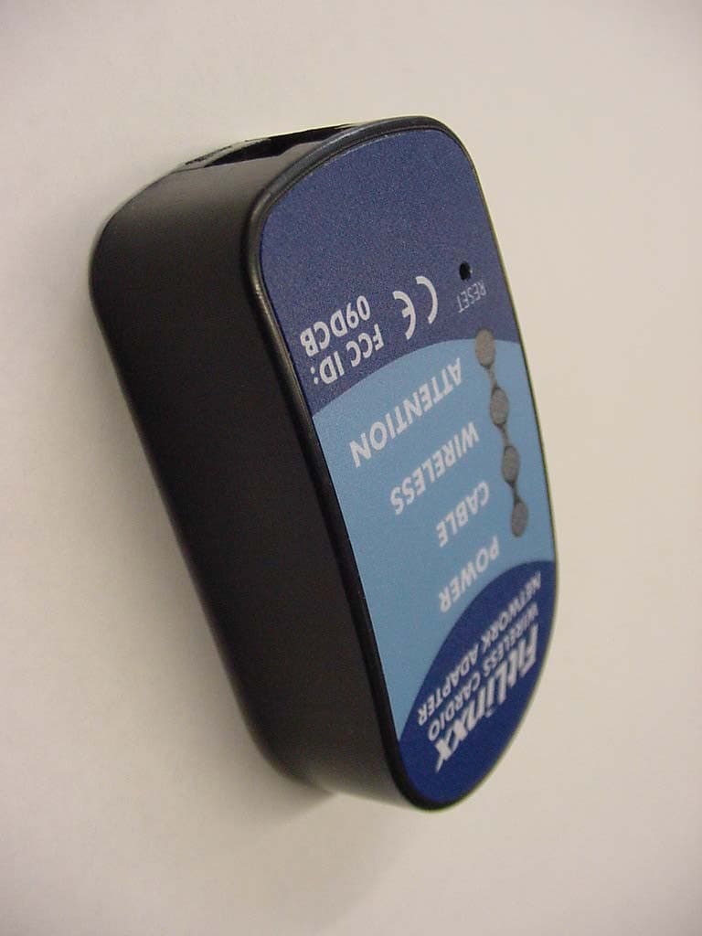
Click to zoom
Application Details
- Equipment Class
- DXX - Part 15 Low Power Communication Device Transmitter
- Date of Grant
- Aug 05, 2007
- Application Purpose
- Original Equipment
- Date of Application
- Aug 05, 2007
- Equipment Note
- Wireless Cardio Network Adapter
- Frequency Range
- 2429.00000000 - 2429.00000000
- Company
- FitLinxx
- Country
- United States
Documents & Files
Document Text
Text extracted from the exhibit documents filed with the FCC. Open a document above to read the original.
Users Manual
PROPRIETARY CBM User Guide Doc Number: 930-00003-01 Proprietary Information Revision History DATEREVISIONDESCRIPTIONAUTHOR 4/04/200701Initial releaseSteven Oliver 4/23/200702Saftey approval updates and FCC modificationsJohn MacLean Approvals The information contained in this document is the sole property of FitSense Technology. Any reproduction in part or whole without the written permission of FitSense Technology is prohibited. FitSense Technology CSAFE BODYLAN MODULE DOC #: 930-00003-01REVISION: 01 1 User Guide 1.1Introduction: The CSAFE BodyLan Module (CBM) provides wireless communication between a CSAFE equipped fitness equipment and the Local Acess Point or Remote Acess Point. Included with a CBM is a 12 inch flat data cable. 1.Installation: Installaton and Serviceing is only to be performed by a qualified technician trained by FitLinxx in the installation of this module. 1.Locate the CSAFE port on the fitness equipment console. 2.The CBM needs to be placed near the CSAFE port and just below the top of the equipments console 3.With a cleaning solvent clean the area on the console where the CBM is going to be placed. 4.On the back of the CBM, peel off the protective cover of the Velcro adhesive and attach it to the console. 5.Insert the small connector end of the data cable into the CBM and the larger end connector into the CSAFE port on the console. © 2006 FITSENSE TECHNOLOGYCONFIDENTIALPAGE 2 OF 3 CSAFE BODYLAN MODULE DOC #: 930-00003-01REVISION: 01 1.3Operation: The following LED configurations represent the operation modes of the CBM. (●) (●) (●) (●) GREEN SolidCSAFE port is providing power (●) (●) (●) (●) GREEN Solid YELLOW Solid CSAFE port is providing power CSAFE port is communicating with the CBM (●) (●) (●) (●) GREEN Solid YELLOW Solid YELLOW Solid CSAFE port is providing power CSAFE port is communicating with the CBM Wireless communication between the CBM and the LAP or RAP (●) (●) (●) (●) GREEN BlinkingCBM is in low power mode (●) (●) (●) (●)RED SolidAttention required 1.4Regulatory: This device complies with Part 15 of the FCC Rules. Operation is subject to the following two conditions: (1) this device may not cause harmful interference and (2) this device must accept any interference received, including interference that may cause undesired operations. Changes or modifications not expressly approved by the party responsible for compliance could void the users authority to operate the device. WARNING Rating 4.7V - 20V 20ma - - - No operator serviceable parts © 2006 FITSENSE TECHNOLOGYCONFIDENTIALPAGE 3 OF 3
ID Label/Location Info
REV CHANGED BY DATE DESCRIPTION - 2/14/2007 m T B S HE E T μ J C D ±0.1 m m 2 P LACE D ECIMAL ± 1 .0 DI MENSIONSI N[ ]AREINC HE S asspecificallyauthorizedbyFitSense,Inc. 214-00028-01 DATE SCAL E: 1 Neitherthisdocumentnortheinformation 1 ADHESIVE-BACKED CLEAR POLYESTER LABEL, MATTE FINISH thereinistobereproduced,distributed,used O F 1 : 1 D S N ' D P A PERSIZE DRAWINGNUMBER M A T ' L DR A W N C H K ' D REV ordisclosedeitherinwholeorinpart,except CBM LABEL E X CE P T A S NOT E D, A LLDI MSAREMM p r o p ri e t a r y i nfo r ma t i on o f FitS e nse , I n c. F ax:508.357.7 9 90 JCD D R A W N DSN'D A DATE C HK 'D SURFACEFINI S H : 3 . 2 A SMEY14.5M- 19 94AP P LI E S 0PLACEDECIM A L ANGU L ARTOL'S 1PL A CED EC IM A L ±0. 25 m m ±1.0 m m Thisdocumentcontainsconfidentialor 2 1B o stonR o ad POB o x 7 30 S outhboro u g h , MA 01 7 72 Phon e :50 8 .3 0 3 . 8811 04 5 MIL TOTAL THICKNESS CB CB
Test Report
RETLIF TESTING LABORATORIES TEST REPORT R-4797N-2 June 27, 2007 FCC COMPLIANCE TEST REPORT ON FITSENSE TECHNOLOGY, INC. CSAFE BODYLAN MODULE (WIRELESS CARDIO NETWORK ADAPTER) FCC ID: 09DCB Test Report No. R-4797N-2 FCC ID:09DCB APPLICANT FITSENSE TECHNOLOGY 21 Boston Road Southborough, MA 01772 MANUFACTURER SAME TEST SPECIFICATION: FCC Rules and Regulations Part 15, Subpart C, Para. 15.249 TEST PROCEDURE: ANSI C63.4:2003 TEST SAMPLE DESCRIPTION BRANDNAME: Fitsense Part #: 710-00032-01 Model: CSAFE Bodylan Module (Wireless Cardio Network Adapter) POWER REQUIREMENTS: Internal Battery FREQUENCY BAND OF OPERATION: 2400 to 2483.5MHz FREQUENCY OF OPERATION : 2429.0MHz FCC ID: 09DCB APPLICABLE RULE SECTION: Part 15, Subpart C, Section 15.249 TESTS PERFORMED 15.249 (a) Fundamental & Harmonic Emissions 15.249 (d) Out of Band/Bandedge Emissions 15.249 (e) Peak Field Strength TEST SAMPLE DESCRIPTION The EUT is a FITSENSE TECHNOLOGY, CSAFE Bodylan Module (Cardio Wireless Network Adapter) Wireless Transceiver which transmits at 2429.0MHz. The intended application is to for communications with fitness equipment by way of it’s CSAFE Port and to transmit data to a local server via wireless communication link. This device is powered by 3.6VDC via internal battery. There is no connection to the AC mains during use. Test Report No. R-4797N-2 FCC ID:09DCB ANTENNA DESCRIPTION The device uses an integral PCB Etch Antenna and has no connection for external antenna. TEST SAMPLE / TEST RESULTS SUMMARY CThe fundamental field strength at 2429.0MHz did not exceed 50mV/M at a test distance of 3 meters. CThe field strength of harmonic emissions did not exceed 500μV/M. No harmonic emissions were observed within 10dB of the specified limit at 3 meter or 1 meter test distances above the second harmonic (4858.26MHz). CThe field strength of non-harmonic out of band/bandedge emissions were attenuated more than 50dB below the level of the fundamental or to the limits of 15.209 as applicable. No out of band spurious emissions were observed within 10dB of the specified limit at 3 meter or 1 meter test distances. •The peak field strength of the fundamental emission did not exceed the maximum permitted average field strength by more than 20dB. CRadiated Emissions from the EUT were measured in all three axis. The worst case fundamental emission was found with the EUT in the “Z” Access. The worst case harmonic emission was found with the EUT in the “Y” Access. MEASUREMENT PROCEDURES 15.249 (a/d/e) Field Strength of Fundamental, Harmonic and Out of Band/Band Edge Emissions & Peak Field Strength The field strength of the fundamental, harmonic and out of band/bandedge emissions were measured. The transceiver was placed on a 80cm high wooden test stand which was located 3 meters from the test antenna on an FCC listed open area test site. Emissions from the EUT were maximized by rotating the test sample and adjusting the test sample orientation and antenna polarization. The maximized field strength of each observed emission was measured, recorded and compared to the specified limits of 15.249 (a), (d)/15.209 as appropriate. Peak field strength of emissions were measured, recorded and verified to meet the specified limit (limit corresponds to 20dB above the maximum permitted average limit). When necessary the marker/delta method was used to verify bandedge compliance. Test Report No. R-4797N-2 FCC ID:09DCB EQUIPMENT LIST Fundamental & Harmonic Emissions ENTypeManufacturerDescriptionModel No.Cal DateDue 3116Pre-AmplifierMiteq0.1 GHz - 18 GHzAFS42-358/25/20068/25/2007 3117Power SupplyB&K Precision0-30 Vdc, 3.0 A16301/23/20071/23/2008 4029BTest Site AttenuationRetlif3 / 10 MetersRNH5/24/20065/24/2007 4895Spectrum AnalyzerHewlett Packard9kHz - 22GHz8593EM2/13/20072/13/2008 4984AHigh Gain HornMicrolab/FXR1.0 - 1.7 GHzL638A1/24/20071/24/2008 4984BHigh Gain HornMicrolab/FXR1.7 - 2.6 GHzR638A1/24/20071/24/2008 4984CHigh Gain HornMicrolab/FXR2.6 - 3.95 GHzS638A1/24/20071/24/2008 4984DHigh Gain HornMicrolab/FXR3.95 - 5.85 GHzH638A1/24/20071/24/2008 4984EHigh Gain HornMicrolab/FXR5.8 - 8.2 GHzC638A1/24/20071/24/2008 4984FHigh Gain HornMicrolab/FXR8.2 - 12.4 GHzX638A1/24/20071/24/2008 4984GHigh Gain HornMicrolab/FXR12.4 GHz - 18 GHzY638A1/24/20071/24/2008 4984HHigh Gain HornMicrolab/FXR18 - 26.5 GHzK638AF1/24/20071/24/2008 5053BiconilogEMCO26 MHz - 3 GHz3142C2/8/20064/8/2007 5070EMI Test ReceiverRohde & Schwarz20Hz - 40GHzESIB4011/22/200611/22/2007 5072PreamplifierMiteq18 GHz-40 GHzJS4-18004000-3001/10/200701/10/2008 Test Report No. R-4797N-2 FCC ID:09DCB RADIATED EMISSIONS TEST SETUP PHOTOGRAPH
Test Setup Photos
Test Report No. R-4797N-2 FCC ID:09DCB RADIATED EMISSIONS TEST SETUP PHOTOGRAPH
Contact Information
Applicant
John E MacLean(Vice President of Manufacturing)
Technical Contact
Retlif Testing LaboratoriesScott Wentworth
[email protected]603-497-4600
101 New Boston Road · Goffstown, New Hampshire · United States
Non-Technical Contact
Retlif Testing LaboratoriesScott Wentworth
[email protected]603-497-4600
Test Firm
Retlif Testing LaboratoriesScott Wentworth
Technical Specifications
| # | Rule Parts | Frequency Range | Power Output |
|---|---|---|---|
| 1 | 15C | 2.43 GHz - 2.43 GHz | - |
Other Applications from FitLinxx
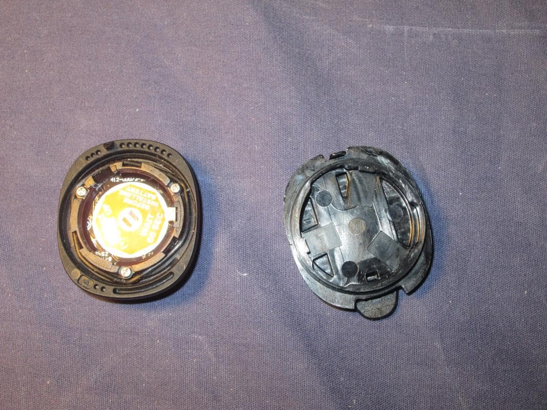
O9DA
Dec 18, 2014Bluetooth Activity Sensor
Equipment Class
DXX - Part 15 Low Power Communication Device Transmitter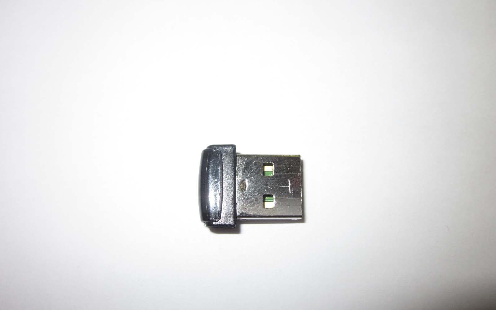
O9DAL3
Nov 20, 2012Wireless Access Point
Equipment Class
DXX - Part 15 Low Power Communication Device Transmitter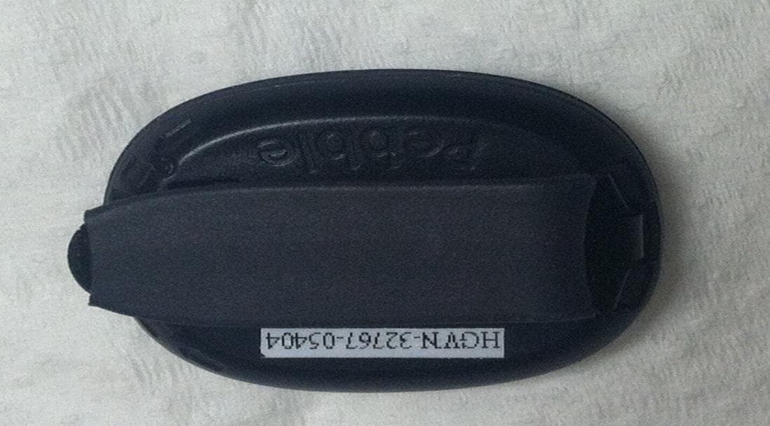
O9DAP5
Jun 10, 2012Wireless Activity Monitor
Equipment Class
DXX - Part 15 Low Power Communication Device Transmitter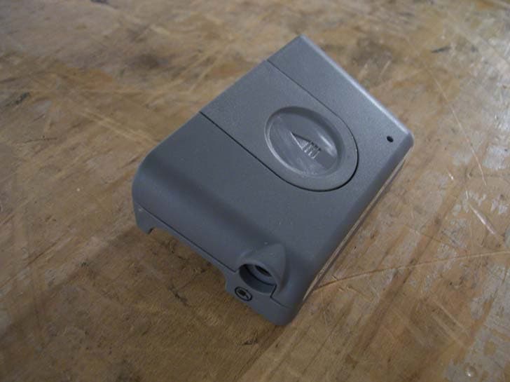
O9DIRB
Dec 05, 2011Alere AirLink for INRatio
Equipment Class
DTS - Digital Transmission System
O9DAP4
Feb 09, 2011Wireless Step Sensor/Pedometer
Equipment Class
DXX - Part 15 Low Power Communication Device Transmitter