O9DSDData Transceiver
FitLinxx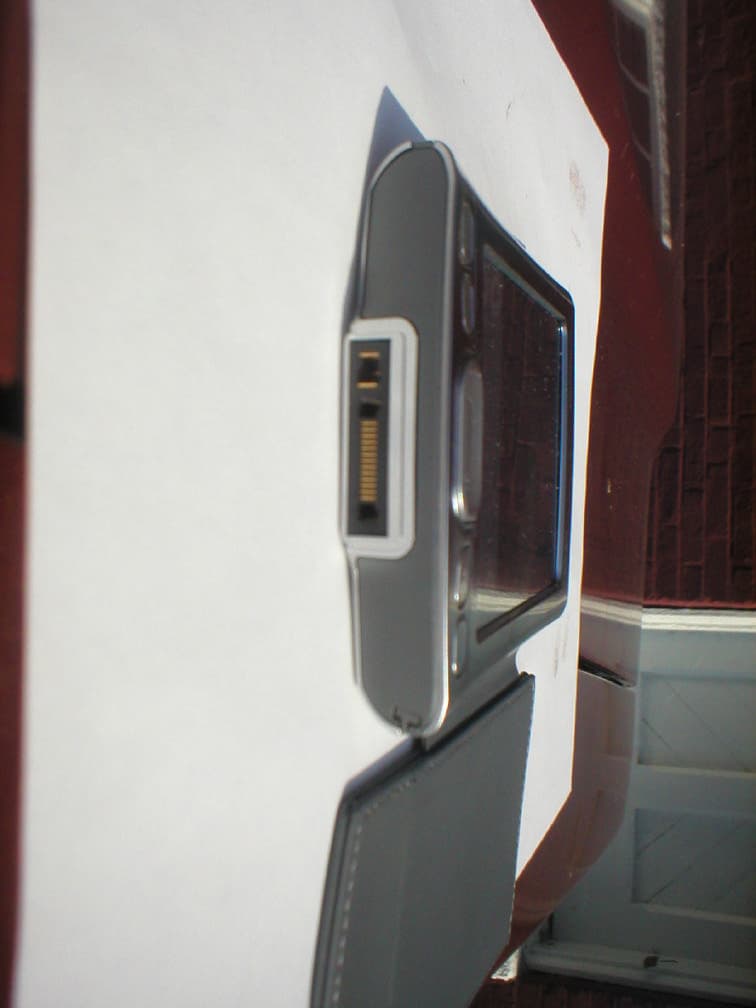
Click to zoom
Application Details
- Equipment Class
- DXX - Part 15 Low Power Communication Device Transmitter
- Date of Grant
- Nov 22, 2005
- Application Purpose
- Original Equipment
- Date of Application
- Nov 22, 2005
- Equipment Note
- Data Transceiver
- Frequency Range
- 2425.00000000 - 2425.00000000
- Company
- FitLinxx
- Country
- United States
Documents & Files
Document Text
Text extracted from the exhibit documents filed with the FCC. Open a document above to read the original.
Users Manual
SDIO Network Adapter Installation and Operating Instructions The SDIO part number 710-00020-01 is a device that interfaces a Palm Tungsten Personal Digital Assistant (PDA) to the FitSense Bodylan RF Network. Installation of the SDIO card is as follows: 1. Install SDIO Software into the Palm 2. Unpack the SDIO/eSense Hub 3. With the eSense Hub lettering facing toward the front of the PDA, place the SDIO gold fingers into the SD port of the PDA. 4. Ensure the SDIO is locked into the port 5. Start up the Application 6. Follow the instruction in the Palm Tungsten Manual to reset the device due to any error conditions that may occur in normal use. Any changes or modification not expressly approved by the party responsible for compliance could void the users authority to operate the device. FCC ID: O9DSD SDIO Network Adapter PHT eSense Hub This device complies with Part 15 of the FCC Rules. Operation is subject to the following two conditions: (1) this device may not cause harmful interference and (2) this device must accept any interference received, including interference that may cause undesired operation.
Cover Letter(s)
Dan, We did not use/need a high pass filter for blocking the fundamental because we used the high gain horn antennas. The roll off in frequency response of these antennas effectively blocked the fundamental and prevented saturation. Use of these antennas accomplishes the same thing as the use of a high pass filter. As you surmised, the statements contained within the report regarding no emissions observed within 20dB of the limit were not accurate due to noise floor limitations. At the tenth harmonic our measurement system noise floor is only 10dB below the general limits. We have revised the test report to reflect this (see attached). Sorry for the oversight. Regards, Scott Wentworth Branch Manager RETLIF TESTING LABORATORIES 101 New Boston Road Goffstown, NH 03045 Tel: 603-497-4600 Fax: 603-497-5281 E-mail: [email protected] CONFIDENTIALITY : This e-mail and any attachments are confidential and may be privileged. If you are not a named recipient, please notify the sender immediately and do not disclose the contents to another person, use it for any purpose or store or copy the information in any medium. From: Daniel E. Crowder [mailto:[email protected]] Sent: Thursday, November 10, 2005 9:47 AM To: 'Scott Wentworth' Cc: 'Richard King' Subject: RE: Fitsense Cert. Application Scott, A couple of questions were asked about the testing. Can you verify that your ambient level is greater than 20 dB below the general limits at the 10 th harmonic? And, do you use any type of high-pass filter for blocking the fundamental? If not, how do you check and prevent the pre-amp for saturation? Regards, Dan Crowder Elite Electronic Engineering, Inc. 630-495-9770 Ext. 101 [email protected] www.elitetest.com "PLEASE NOTE": The preceding information may be confidential or privileged. It only should be used or disseminated for the purpose of conducting business with Elite Electronic Engineering, Inc. If you are not the intended recipient, please notify the sender by replying to this message and then delete the information from your system. Thank you for your cooperation."
ID Label/Location Info
REV CHANGED BY DATE DESCRIPTION - 7/15/2005 m T B S H E E T μ J C D ±0.1 m m 2 P LACE D ECIMAL ± 1 .0 DI MENSIONSI N[ ]AREINC HE S a s sp e cifica ll y a u t horizedb yFitSense , I nc. 214-00011-01 DATE SCAL E: 1 Ne it h e rthisd o cume n t no r t h ei nfo r ma t i o n 1 Dr a wnb y S o l i d W or ks WHITE, MATTE POLYESTER, 1 MIL THICK, 1 MIL CLEAR COAT t h er e in is tob e r e p r oduce d , d ist r ib u t e d , use d O F 1 : 1 D S N ' D P A PERS I ZE DR A WIN G N U MBE R M A T ' L DR A W N C H K ' D REV o r di s clo se d e it h e rin wh o le o ri np a r t , e xce p t LABEL, SDIO E X CE P T A S NOT E D, A LLDI MSAREMM p r o p ri e t a r y i nfo r ma t i on o f FitS e nse , I n c. F ax:508.357.7 9 90 JCD D R A W N DSN'D A DATE C HK 'D SURFACEFINI S H : 3 . 2 A SMEY14.5M- 19 94AP P LI E S 0PLACEDECIM A L ANGU L ARTOL'S 1PL A CED EC IM A L ±0. 25 m m ±1.0 m m Thisd o cument co nta in s co nfiden t ia l or 2 1B o stonR o ad POB o x 7 30 S outhboro u g h , MA 01 7 72 Phon e :50 8 .3 0 3 . 8811 01 NOTES: - USE GRAPHICS AS SHOWN IN FILE. DO NOT RE-SET TYPE. - OUTSIDE SHAPE INDICATES DIE CUT. HIGH TACK PERMANENT ACRYLIC ADHESIVE BLACK FLOOD WHITE GRAPHICS AND TYPE (KNOCKOUT OR PRINTED) 01 JCD 9/28/2005 INITIAL RELEASE OF DRAWING 100% 200%
Test Report
RETLIF TESTING LABORATORIES TEST REPORT R-4494N1 October 15, 2005 FCC COMPLIANCE TEST REPORT ON FITSENSE TECHNOLOGY, INC. PALM TUNGSTEN E PDA WITH SDIO WIRELESS TRANSCEIVER FCC ID: 09DSD Test Report No. R-4494N1 FCC ID:09DSD APPLICANT FITSENSE TECHNOLOGY 21 Boston Road Southborough, MA 01772 MANUFACTURER SAME TEST SPECIFICATION: FCC Rules and Regulations Part 15, Subpart C, Para. 15.249 TEST PROCEDURE: ANSI C63.4:2001 TEST SAMPLE DESCRIPTION BRANDNAME: Fitsense MODEL: 71000020-01 TYPE: PALM TUNGSTEN E PDA WITH SDIO WIRELESS TRANSCEIVER POWER REQUIREMENTS: Internal Battery FREQUENCY BAND OF OPERATION: 2400 to 2483.5MHz FREQUENCY OF OPERATION : 2425.15MHz FCC ID: 09DSD APPLICABLE RULE SECTION: Part 15, Subpart C, Section 15.249 TESTS PERFORMED 15.249 (a) Fundamental & Harmonic Emissions 15.249 (d) Out of Band/Bandedge Emissions 15.249 (e) Peak Field Strength TEST SAMPLE DESCRIPTION The EUT is a PALM TUNGSTEN E PDA with FITSENSE TECHNOLOGY, SDIO Wireless Transceiver Transmitting at 2425.15MHz. The intended application is to interface the PALM TUNGSTEN E PDA with the Fitsense BodyLan RF Network via 2.4GHz Radio Link and pass data packets between the PDA and another external device. This device is powered by 3VDC via the PDA (internal battery). The application for this PDA with SDIO Wireless Card is strictly portable with no connection to AC mains during use. Test Report No. R-4494N1 FCC ID:09DSD ANTENNA DESCRIPTION The device uses an integral Chip Antenna with a gain of approximately 6dB and thus has no connection for external antenna. TEST SAMPLE / TEST RESULTS SUMMARY CThe fundamental field strength at 2415.25MHz did not exceed 50mV/M at a test distance of 3 meters. CThe field strength of harmonic emissions did not exceed 500μV/M. No harmonic emissions were observed within 10dB of the specified limit at 3 meter or 1 meter test distances above the second harmonic (4850.30MHz). CThe field strength of non-harmonic out of band/bandedge emissions were attenuated more than 50dB below the level of the fundamental or to the limits of 15.209 as applicable. No out of band spurious emissions were observed within 10dB of the specified limit at 3 meter or 1 meter test distances. •The peak field strength of the fundamental emission did not exceed the maximum permitted average field strength by more than 20dB. CRadiated Emissions from the EUT were measured in all three axis. Worst case emissions were found with the EUT in the “Z” Access. The attached Radiated Emissions test data is representative of this worst case orientation. MEASUREMENT PROCEDURES 15.249 (a/d) Field Strength of Fundamental, Harmonic and Out of Band/Band Edge Emissions The field strength of the fundamental, harmonic and out of band/bandedge emissions were measured. The transceiver was placed on a 80cm high wooden test stand which was located 3 meters from the test antenna on an FCC listed open area test site. Emissions from the EUT were maximized by rotating the test sample and adjusting the test sample orientation and antenna polarization. The maximized field strength of each observed emission was measured, recorded and compared to the specified limits of 15.249 (a), (d)/15.209 as appropriate. Peak field strength of emissions were measured, recorded and verified to meet the specified limit (limit corresponds to 20dB above the maximum permitted average limit). When necessary the marker/delta method was used to verify bandedge compliance. Test Report No. R-4494N1 FCC ID:09DSD EQUIPMENT LIST Fundamental, Harmonic and Out of Band Emissions ENTypeManufacturerDescriptionModel No.Cal DateDue 3430Horn AntennaMCS Corporation18 GHz - 26.5 GHzK-50391/25/20051/25/2006 4029BTest Site AttenuationRetlif3 / 10 MetersRNH12/3/200412/3/2005 4984BHigh Gain HornMicrolab/FXR1.7 - 2.6 GHzR638A1/25/20051/25/2006 4984DHigh Gain HornMicrolab/FXR3.95 - 5.85 GHzH638A1/25/20051/25/2006 4984EHigh Gain HornMicrolab/FXR5.8 - 8.2 GHzC638A1/25/20051/25/2006 4984FHigh Gain HornMicrolab/FXR8.2 - 12.4 GHzX638A1/25/20051/25/2006 4984GHigh Gain HornMicrolab/FXR12.4 GHz - 18 GHzY638A1/25/20051/25/2006 713EMI Test ReceiverRohde & Schwarz20 Hz - 26.5 GHzESI263/22/20053/22/2006 4202BiconilogEMCO26 MHz - 2 GHz314212/13/200412/13/2005 4984AHigh Gain HornMicrolab/FXR1.0 - 1.7 GHzL638A1/25/20051/25/2006 R120PreamplifierHewlett Packard1.0 -26.5 GHz8449B7/08/20057/08/2006 Test Report No. R-4494N1 FCC ID:09DSD Test Report No. R-4494N1 FCC ID:09DSD TEST SETUP PHOTOGRAPHS Test Report No. R-4494N1 FCC ID:09DSD TEST SETUP PHOTOGRAPHS
Test Setup Photos
Test Report No. R-4494N1 FCC ID:09DSD Test Report No. R-4494N1 FCC ID:09DSD TEST SETUP PHOTOGRAPHS Test Report No. R-4494N1 FCC ID:09DSD TEST SETUP PHOTOGRAPHS
Contact Information
Applicant
John E MacLean(Vice President of Manufacturing)
Technical Contact
Retlif Testing LaboratoriesScott Wentworth
[email protected]603-497-4600
101 New Boston Road · Goffstown, New Hampshire · United States
Non-Technical Contact
Retlif Testing LaboratoriesScott Wentworth
[email protected]603-497-4600
Test Firm
Retlif Testing LaboratoriesScott Wentworth
Technical Specifications
| # | Rule Parts | Frequency Range | Power Output |
|---|---|---|---|
| 1 | 15C | 2.42 GHz - 2.42 GHz | - |
Other Applications from FitLinxx
O9DA
Dec 18, 2014Bluetooth Activity Sensor
Equipment Class
DXX - Part 15 Low Power Communication Device Transmitter
O9DAL3
Nov 20, 2012Wireless Access Point
Equipment Class
DXX - Part 15 Low Power Communication Device Transmitter
O9DAP5
Jun 10, 2012Wireless Activity Monitor
Equipment Class
DXX - Part 15 Low Power Communication Device Transmitter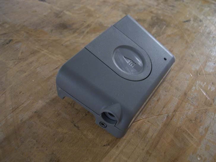
O9DIRB
Dec 05, 2011Alere AirLink for INRatio
Equipment Class
DTS - Digital Transmission System
O9DAP4
Feb 09, 2011Wireless Step Sensor/Pedometer
Equipment Class
DXX - Part 15 Low Power Communication Device Transmitter