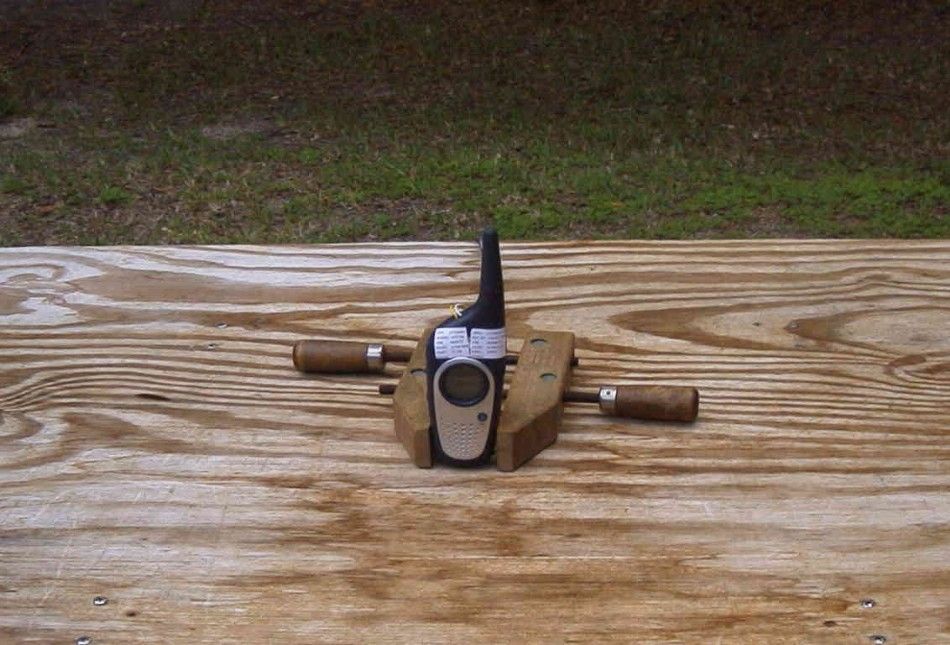
OAJATT704FRS/ GMRS + GPS + NOAA Transceiver
J Communications Co Ltd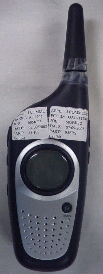
Click to zoom
Application Details
- Equipment Class
- FRF - Part 95 Family Radio Face Held Transmitter
- Date of Grant
- Sep 25, 2002
- Application Purpose
- Original Equipment
- Date of Application
- Sep 25, 2002
- Equipment Note
- FRS/ GMRS + GPS + NOAA Transceiver
- Frequency Range
- 462.56250000 - 467.71250000
- Company
- J Communications Co Ltd
- Country
- South Korea
Documents & Files
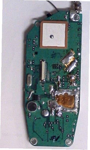
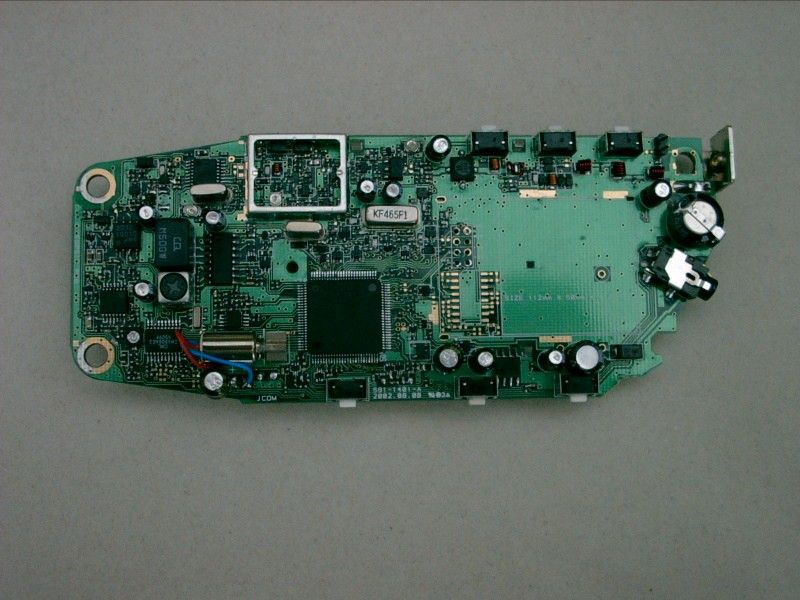
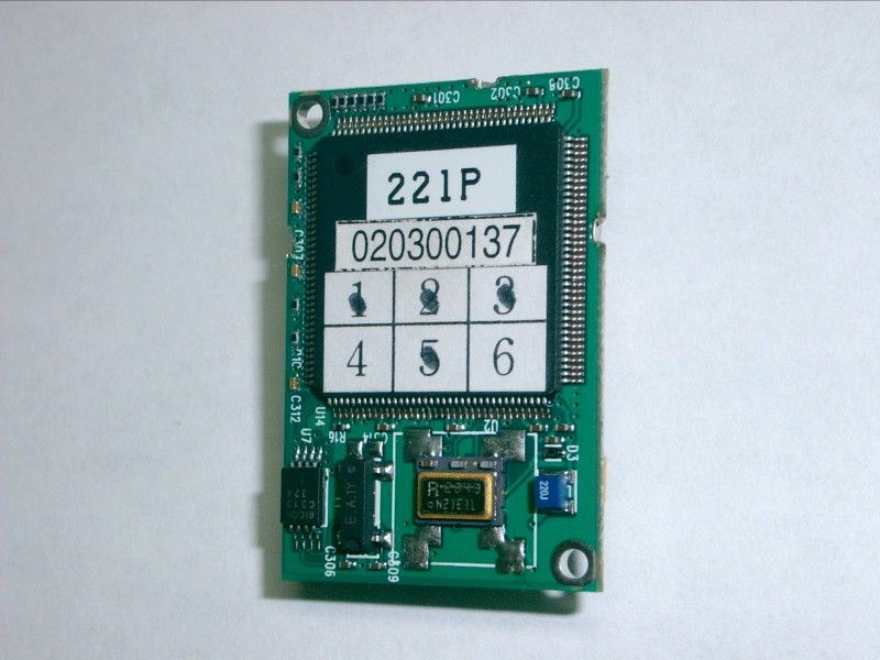
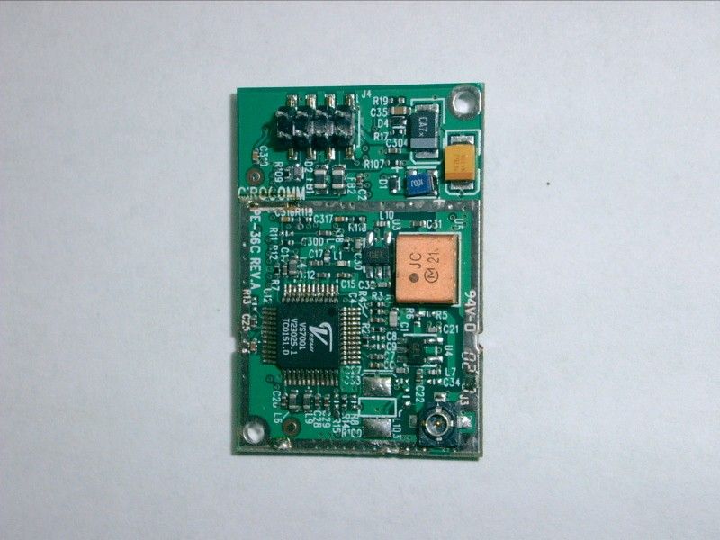
Document Text
Text extracted from the exhibit documents filed with the FCC. Open a document above to read the original.
Users Manual
– ’ ’ 64 * 80 Resolution FCC WARNING Replacement or substitution of transistors, diodes or other parts of a unique nature, with parts other than those recommended by the manufacturer, may cause a violation of the technical regulations of Part 15 of FCC Rules. SAFETY INFORMATION Your wireless hand-held portable transceiver contains a low power transmitter. When the PTT button is pushed it sends out radio frequency (RF) signals. The device is authorize d to operate at a duty factor not to exceed 50% using alkaline "AAA" size batteries to comply with Federal Communications Commissions (FCC) RF exposure guidelines with safety level guidelines for hand-held wireless devices. Important: To maintain compliance with the FCC’s RF exposure guidelines hold the transmitter at least 1 inch away (2.5 centimeters) from your face and speak in a normal voice, with the antenna pointed up and away. If you wear the handset on your body while using the headset accessory, use only the AT&T supplied belt clip for this product and ensure that the antenna is at least 1 inch (2.5 centimeters) from your body when transmitting. Use only the supplied antenna. Unauthorized antennas, modifications, or attachments could damage the transmitter and may violate FCC regulations. GMRS License: Use of GMRS radios within the United States requires a FCC GMRS licence. An individual 18 years of age or older who is not a representative of a foreign government is eligible to apply for a GMRS system license. You will need two forms from the FCC, FCC form 159 and form 605 Main Form and Schedule F. You can find the forms online at http://www.fcc.gov/formpage.html or call 1-800-418-3676. The FCC requires that you be advised of certain requirements involving the use of this device. This equipment has been tested and found to comply with the limits for a Class B digital device, pursuant to Part 15 of the FCC rules. These limits are designed to provide reasonable protection against harmful interference in a residential installation. This equipment uses and can generate radio frequency energy, if not installed and used in accordance with the instruction, it may cause harmful interference to radio communications. However, there is no guarantee that the interference will not occur in a particular installation. If this equipment does cause harmful interference to radio or television reception(which can be determined by turning the equipment off and on), the user is encouraged to correct the interference by one of the following measures: 1. Reorient or relocate the receiving antenna. 2. Increase the separation between the equipment and receiver 3. Connect the equipment to an outlet on a circuit different from that to which the receiver is connected. 4. Consult the manufacturer for technical assistance.
Operational Description
’’
Test Report
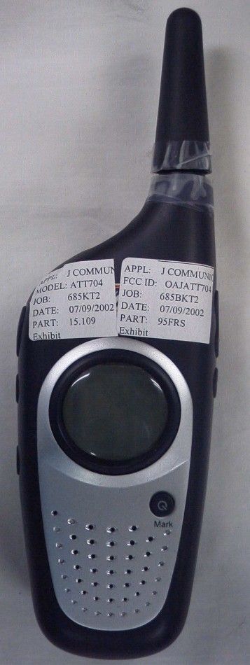
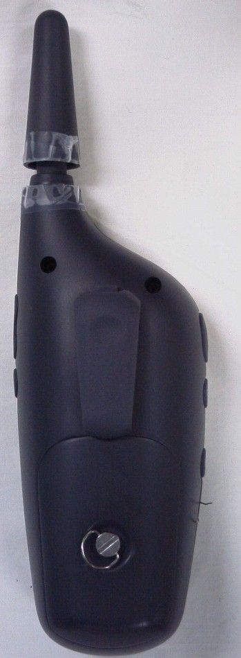
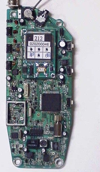
APPLICANT: J COMMUNICATIONS CO., LTD. FCC ID: OAJATT704 REPORT #: J\Jcom_OAJ\685BKT2\685BKT2TestReport.doc TABLE OF CONTENTS TABLE OF CONTENTS LIST APPLICANT: J COMMUNICATIONS CO., LTD. FCC ID: OAJATT704 TEST REPORT: PAGE 1......COVER SHEET - GENERAL INFORMATION & TECHNICAL DESCR. PAGE 2......TECHNICAL DESCRIPTION CONTINUED PAGE 3......RF POWER OUTPUT PAGE 4......MODULATION CHARACTERISTICS PAGE 5......AUDIO FREQUENCY RESPONSE GRAPH PAGE 6......MODULATION LIMITING GRAPH – 300Hz PAGE 7......MODULATION LIMITING GRAPH – 1000Hz PAGE 8......MODULATION LIMITING GRAPH – 3000Hz PAGE 9......AUDIO LOW PASS FILTER GRAPH PAGE 10.....OCCUPIED BANDWIDTH PAGE 11.....OCCUPIED BANDWIDTH PLOT PAGE 12.....OCCUPIED BANDWIDTH PLOT - CW PAGE 13.....SPURIOUS EMISSIONS AT ANTENNA TERMINALS PAGE 14.....UNWANTED RADIATION - GMRS PAGE 15.....UNWANTED RADIATION - FRS PAGE 16.....METHOD OF MEASURING RADIATED SPURIOUS EMISSIONS PAGE 17.....FREQUENCY STABILITY PAGE 18-21..LIST OF TEST EQUIPMENT EXHIBITS CONTAINING: EXHIBIT 1.........FCC ID LABEL SAMPLE EXHIBIT 2.........FCC ID LABEL LOCATION EXHIBIT 3.........BLOCK DIAGRAM EXHIBIT 4.........SCHEMATIC EXHIBIT 5.........EXTERNAL PHOTOGRAPH – FRONT VIEW EXHIBIT 6.........EXTERNAL PHOTOGRAPH – REAR VIEW EXHIBIT 7.........INTERNAL PHOTOGRAPH – COMPONENT VIEW EXHIBIT 8.........INTERNAL PHOTO – COPPER VIEW EXHIBIT 9.........USERS MANUAL EXHIBIT 10........OPERATIONAL DESCRIPTION EXHIBIT 11........TUNING PROCEDURE EXHIBIT 12........TEST SETUP PHOTOGRAPH APPLICANT: J COMMUNICATIONS CO., LTD. FCC ID: OAJATT704 REPORT #: J\Jcom_OAJ\685BKT2\685BKT2TestReport.doc Page 1 of 21 GENERAL INFORMATION REQUIRED FOR CERTIFICATION 2.1033(c)(1)(2) J COMMUNICATIONS CO., LTD. will manufacture the FCCID: OAJATT704 GMRS/FRS COMBINATION TRANSCEIVER in quantity, for use under FCC RULES PART 95. J COMMUNICATIONS CO., LTD. 124-4 OJEON-DONG, UIWANG-CITY KYUNGKI-DO KOREA 2.1033 (c) TECHNICAL DESCRIPTION 2.1033(c)(3) Instruction book. A draft copy of the instruction manual is included as EXHIBIT 9. 2.1033(c) (4) Type of Emission: 8K4F3E 95.631 Bn = 2M + 2DK M = 3000 D = 1.2K Bn = 2(3000)+2(1200) = 8400 GMRS Authorized Bandwidth 20.0 kHz 2.1033(c)(5) GMRS Frequency Range: 1. 462.5500 13. 462.7000 95.621 2. 462.5625 14. 462.7125 3. 462.5750 15. 462.7250 4. 462.5875 16. 467.5500 5. 462.6000 17. 467.5750 6. 462.6125 18. 467.6000 7. 462.6250 19. 467.6250 8. 462.6375 20. 467.6500 9. 462.6500 21. 467.6750 10. 462.6625 22. 467.7000 11. 462.6750 23. 467.7250 12. 462.6875 2.10311c)(6)(7) The Maximum Output Power Rating: GMRS HIGH - 2.3 Watts ERP GMRS LOW - 0.56 Watts ERP FRS - 0.42 Watts ERP FRS Authorized Bandwidth 12.5kHz 2.1033(c)(5) FRS Frequency Range: 1. 462.5625 8. 467.5625 95.627 2. 462.5875 9. 467.5875 3. 462.6125 10. 467.6125 4. 462.6375 11. 467.6375 5. 462.6625 12. 467.6625 6. 462.6875 13. 467.6875 7. 462.7125 14. 467.7125 MHz APPLICANT: J COMMUNICATIONS CO., LTD. FCC ID: OAJATT704 REPORT #: J\Jcom_OAJ\685BKT2\685BKT2TestReport.doc Page 2 of 21 2.1033(c)(6)(7) Power Output shall not exceed 0.50 Watts effective 95.639 radiated power. There can be no provisions for 95.649 increasing the power or varying the power. 2.1033(c)(8) DC Voltages and Current into Final Amplifier: FINAL AMPLIFIER ONLY FOR LOW POWER SETTING INPUT POWER: (6.0V)(.78A) = 4.68 Watts FOR HIGH POWER SETTING INPUT POWER: (6.0V)(1.17A) = 7.02 Watts 2.1033(c)(9) Tune-up procedure. The tune-up procedure is included as EXHIBIT # 11. 2.1033(c)(10) Complete Circuit Diagrams: The circuit diagram is included as EXHIBIT 4 of this report. The block diagrams are included as EXHIBIT 3 of this report. 2.1033(c)(11) A photograph or a drawing of the equipment identification label is included as exhibit No. 1. 2.1033(c)(12) Photographs(8"X10") of the equipment of sufficient clarity to reveal equipment construction and layout, including meters, labels for controls, including any view under shields. See exhibits 5-8. 2.1033(c)(13) Digital modulation is not allowed. 2.1033(c)(14) The data required by 2.1046 through 2.1057 is submitted below. APPLICANT: J COMMUNICATIONS CO., LTD. FCC ID: OAJATT704 REPORT #: J\Jcom_OAJ\685BKT2\685BKT2TestReport.doc Page 3 of 21 APPLICANT: J COMMUNICATIONS CO., LTD. FCC ID: OAJATT704 REPORT #: J\Jcom_OAJ\685BKT2\685BKT2TestReport.doc Page 4 of 21 95.639 Power Output shall not exceed 50.0 Watts effective radiated power. There can be no provisions for 95.649 increasing the power or varying the power. 2.1046(a) RF power is measured by the substitution method as outlined in TIA/EIA - 603. With a nominal battery voltage of 6.0 V, and the transmitter properly adjusted the RF output measures: OUTPUT POWER: GMRS: HIGH - 2.30 Watts ERP LOW – 0.56 Watts ERP FRS: 0.42 Watts ERP 2.1046(a) RF power output. The test procedure used was TIA/EIA-603 S2 APPLICANT: J COMMUNICATIONS CO., LTD. FCC ID: OAJATT704 REPORT #: J\Jcom_OAJ\685BKT2\685BKT2TestReport.doc Page 5 of 21 2.1047(a)(b) Modulation characteristics: AUDIO FREQUENCY RESPONSE The audio frequency response was measured in ac- cordance with TIA/EIA Specification 603. The audio frequency response curve is shown on the next page. The audio signal was fed into a dummy microphone circuit and into the microphone connector. The input required to produce 30 percent modulation level was measured. See Page 5 of report. 2.1047(b) Audio input versus modulation The audio input level needed for a particular per- percentage of modulation was measured in accor- dance with TIA/EIA Specification 603. The audio input curves versus modulation are on the following pages. Curves are provided for audio input frequen- cies of 300, 1000, and 3000 Hz. See Pages 6,7 & 8 of report. 95.637 Post Limiter Filter Each GMRS transmitter, except a mobile station transmitter with a power of 2.5Watts or less, must be equipped with an audio low pass filter. At any frequency between 3 & 20 kHz the filter must have an attenuation of 60log (f/3) greater than the attenuation at 1KHz. See Page 9 of report. APPLICANT: J COMMUNICA…
Text truncated - open the document above for the full version.
Contact Information
Applicant
C H YOO(Assistant Manager)
Test Firm
Timco Engineering, Inc.S Sanders
Technical Specifications
| # | Rule Parts | Frequency Range | Power Output | Emission | Tolerance |
|---|---|---|---|---|---|
| 3 | 95B | 462.5625 MHz - 467.7125 MHz | 420.00 mW | 8K4F3E | 0.00025 % |
Other Applications from J Communications Co Ltd
OAJBGP2000
Dec 13, 2004Bluetooth GPS Receiver
Equipment Class
DTS - Digital Transmission System
OAJBAG-1000
May 29, 2003Bluetooth Audio Gateway
Equipment Class
DSS - Part 15 Spread Spectrum Transmitter
OAJBH-1000
Dec 29, 2002Bluetooth Headset
Equipment Class
DSS - Part 15 Spread Spectrum Transmitter
OAJBAG-2000
Dec 29, 2002Bluetooth Audio Gateway
Equipment Class
DSS - Part 15 Spread Spectrum Transmitter
OAJBA-1000U
Dec 23, 2002Bluetooth USB Dongle
Equipment Class
DSS - Part 15 Spread Spectrum Transmitter