OAJBAG-1000Bluetooth Audio Gateway
J Communications Co Ltd
Click to zoom
Application Details
- Equipment Class
- DSS - Part 15 Spread Spectrum Transmitter
- Date of Grant
- May 29, 2003
- Application Purpose
- Original Equipment
- Date of Application
- May 29, 2003
- Equipment Note
- Bluetooth Audio Gateway
- Frequency Range
- 2402.00000000 - 2480.00000000
- Company
- J Communications Co Ltd
- Country
- South Korea
Documents & Files
Document Text
Text extracted from the exhibit documents filed with the FCC. Open a document above to read the original.
Users Manual
BAG 1000 Hands-free system for corded regular telephones Operating manual J Communication Co., Ltd General information BAG 1000 The headset BAG 1000 is a comfortably to wear hands-free headset for regular telephones (i.e. office telephone systems). The new Bluetooth TM technology gives you the opportunity for reliable and bug-free wireless transmission to your existing telephone. The system consists of a headset and an audio gateway that ensures connection to the presently used telephone handset. This audio gateway can be used as charging station and as well for storing. Package includes: • Headset with integrated Bluetooth TM technology and Lithium-Ion rechargeable batteries. • Audio-Gateway with charging station for storing, charging of headset and as connection to your existing telephone. • AC/DC Adaptor DG-0550C for audio-gateway and for charging. - Input rated: 230Vac, 50Hz, 35mA - Output rated: 5Vdc, 500mA - Dae Gyung Enterprise Co.,Ltd, Model DG-0550C • Neck strap for headset. • Plug-in telephone cable to be installed between audio gateway and telephone. Basisteil Audio Gateway Reset/Pairing Taste Telefon-Kabel Holder for charging Test- and Pairing-Button Telephone Cable Additional Charging Station (optional available) 230 V-Adapter DG-0550C Note : Use only power supplies listed in the user instructions Hardware requirements for existing telephone and safety advice: Almost all wired telephones with a conventional handset and a plug-in handset cable can be connected. Today nearly all modern home- and office telephones are equipped with a plug-in receiver cable (4 pin “Western” sockets). The BAG 1000 only replaces the microphone and the earpiece of your telephone handset so that you can move around within a range of several meters of your work place without any cables. You can use the BAG 1000 at analogue as well as ISDN- or proprietary telephone systems. The following telephones can not be connected: • Designer telephones where additional electronic devices (i. e. buttons, displays) are installed in the handset • Telephones with carbon, dynamic or piecoceramic microphones (mostly older models) which are not yet equipped with state-of-the art electret microphones • Telephones with special handsets In case of doubt please contact the company that services your telephone system. Please use only the supplied accessories. Operate the audio gateway only in connection with the specially designed wall charger, other chargers may damage the set or cause undesired effects on the telephone line. Never open the headset or try to change or even open the lithium battery by yourself! Hint: The headset can also be connected with other appliances equipped with Bluetooth™ technology such as mobile phones and future DECT-telephone systems with Bluetooth™ technology. In this case the audio gateway will only be used to plug in the headset for charging, the handset cable connectors will remain unused. Pairing has to be done according to the manuals of the respective manufacturer. Observe the relevant chapter at the end of this manual. Connecting the audio-gateway to your existing telephone • Unplug the cable of the handset you presently use and insert it in the lateral socket of the audio gateway (1). • Plug in one end of the supplied straight telephone cable in the now free socket of your hand receiver, the other end plug in the free socket at the bottom of your audio gateway. You can lead the cable outside via the 2 slots in the plastic. (2) • Connect the DC plug of the wall charger with the socket marked „DC 5V“ at the right side of your audio-gateway. Plug the wall charger in a 1 2 230V socket. • Insert the Bluetooth™ headset in the audio gate way as shown below. The charging light at the audio gateway will light up. • Lift up your telephone handset. You should hear the normal dial tone and be able to use your telephone (with the original handset) as usual. In case you don ́t hear anything, check the newly plugged-in connections and check out the other positions of the slide switch at the bottom of the audio gateway. One of the 8 positions will give you your desired signal. Leave the switch in this position. The switch is needed to cover the variety of wirings of wired telephones of the different brands. In most cases the preselected position (1) will be the right one. Charging the BAG 1000 in the charging cradle of the audio gateway Charging starts the moment the headset is being inserted in the audio gateway. It takes approx. 1.5 to 2.5 hours to fully charge a completely empty BAG 1000. The left indicator light gives you information of the state of charging. (Orange = charging, green = battery full). A red light indicates either a defect of the battery or that the headset is not in the correct position in the audio gateway. • You can reduce the charging time by switching off the Bluetooth™ headset before charging (in direction of the arrow). handset connection Important advice to prepare the headset before wearing on your ear The headset is being delivered folded up. The same position is used for charging in the charging station or for storing. To wear it on your ear please turn the microphone arm (1) as indicated downwards. The earhook (2) is flexible at the end so that it can be adjusted to the individual ear shape. To wear it on your ear fold the earhook (3) backwards for no more than 1 or 2 cm. The earhook (3) can be adjusted in the rear part (4) so that it fits perfectly to your ear. The headset is simply hung up on the right ear (5). It will fit comfortably, if you adjust the flexible part of the earhook (4, 5) to your ear’s shape. Hint: Please refrain from folding out the earmount any further than necessary. There should only be enough space between the headset and your ear to ensure a comfortable position. Under no circumstances should the earmount be folded like the microphone! Putting your Bluetooth™ headset into operation After having charged your headset for a while it is now ready for…
Text truncated - open the document above for the full version.
Users Manual
BAG 1000 Hands-free system for corded regular telephones Operating manual J Communication Co., Ltd General information BAG 1000 The headset BAG 1000 is a comfortably to wear hands-free headset for regular telephones (i.e. office telephone systems). The new Bluetooth TM technology gives you the opportunity for reliable and bug-free wireless transmission to your existing telephone. The system consists of a headset and an audio gateway that ensures connection to the presently used telephone handset. This audio gateway can be used as charging station and as well for storing. Package includes: • Headset with integrated Bluetooth TM technology and Lithium-Ion rechargeable batteries. • Audio-Gateway with charging station for storing, charging of headset and as connection to your existing telephone. • AC/DC Adaptor DG-0550C for audio-gateway and for charging. - Input rated: 230Vac, 50Hz, 35mA - Output rated: 5Vdc, 500mA - Dae Gyung Enterprise Co.,Ltd, Model DG-0550C • Neck strap for headset. • Plug-in telephone cable to be installed between audio gateway and telephone. Basisteil Audio Gateway Reset/Pairing Taste Telefon-Kabel Holder for charging Test- and Pairing-Button Telephone Cable Additional Charging Station (optional available) 230 V-Adapter DG-0550C Note : Use only power supplies listed in the user instructions Hardware requirements for existing telephone and safety advice: Almost all wired telephones with a conventional handset and a plug-in handset cable can be connected. Today nearly all modern home- and office telephones are equipped with a plug-in receiver cable (4 pin “Western” sockets). The BAG 1000 only replaces the microphone and the earpiece of your telephone handset so that you can move around within a range of several meters of your work place without any cables. You can use the BAG 1000 at analogue as well as ISDN- or proprietary telephone systems. The following telephones can not be connected: • Designer telephones where additional electronic devices (i. e. buttons, displays) are installed in the handset • Telephones with carbon, dynamic or piecoceramic microphones (mostly older models) which are not yet equipped with state-of-the art electret microphones • Telephones with special handsets In case of doubt please contact the company that services your telephone system. Please use only the supplied accessories. Operate the audio gateway only in connection with the specially designed wall charger, other chargers may damage the set or cause undesired effects on the telephone line. Never open the headset or try to change or even open the lithium battery by yourself! Hint: The headset can also be connected with other appliances equipped with Bluetooth™ technology such as mobile phones and future DECT-telephone systems with Bluetooth™ technology. In this case the audio gateway will only be used to plug in the headset for charging, the handset cable connectors will remain unused. Pairing has to be done according to the manuals of the respective manufacturer. Observe the relevant chapter at the end of this manual. Connecting the audio-gateway to your existing telephone • Unplug the cable of the handset you presently use and insert it in the lateral socket of the audio gateway (1). • Plug in one end of the supplied straight telephone cable in the now free socket of your hand receiver, the other end plug in the free socket at the bottom of your audio gateway. You can lead the cable outside via the 2 slots in the plastic. (2) • Connect the DC plug of the wall charger with the socket marked „DC 5V“ at the right side of your audio-gateway. Plug the wall charger in a 1 2 230V socket. • Insert the Bluetooth™ headset in the audio gate way as shown below. The charging light at the audio gateway will light up. • Lift up your telephone handset. You should hear the normal dial tone and be able to use your telephone (with the original handset) as usual. In case you don ́t hear anything, check the newly plugged-in connections and check out the other positions of the slide switch at the bottom of the audio gateway. One of the 8 positions will give you your desired signal. Leave the switch in this position. The switch is needed to cover the variety of wirings of wired telephones of the different brands. In most cases the preselected position (1) will be the right one. Charging the BAG 1000 in the charging cradle of the audio gateway Charging starts the moment the headset is being inserted in the audio gateway. It takes approx. 1.5 to 2.5 hours to fully charge a completely empty BAG 1000. The left indicator light gives you information of the state of charging. (Orange = charging, green = battery full). A red light indicates either a defect of the battery or that the headset is not in the correct position in the audio gateway. • You can reduce the charging time by switching off the Bluetooth™ headset before charging (in direction of the arrow). handset connection Important advice to prepare the headset before wearing on your ear The headset is being delivered folded up. The same position is used for charging in the charging station or for storing. To wear it on your ear please turn the microphone arm (1) as indicated downwards. The earhook (2) is flexible at the end so that it can be adjusted to the individual ear shape. To wear it on your ear fold the earhook (3) backwards for no more than 1 or 2 cm. The earhook (3) can be adjusted in the rear part (4) so that it fits perfectly to your ear. The headset is simply hung up on the right ear (5). It will fit comfortably, if you adjust the flexible part of the earhook (4, 5) to your ear’s shape. Hint: Please refrain from folding out the earmount any further than necessary. There should only be enough space between the headset and your ear to ensure a comfortable position. Under no circumstances should the earmount be folded like the microphone! Putting your Bluetooth™ headset into operation After having charged your headset for a while it is now ready for…
Text truncated - open the document above for the full version.
External Photos
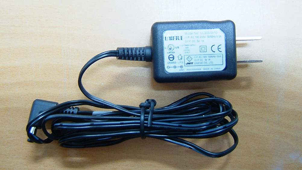
ETC Report No. : ET92R-03-058-03 FCC ID. : OAJBAG-1000 CONSTRUCTED PHOTOS of EUT Top View of EUT Bottom View of EUT ETC Report No. : ET92R-03-058-03 FCC ID. : OAJBAG-1000 CONSTRUCTED PHOTOS of EUT Front View of EUT Rear View of EUT ETC Report No. : ET92R-03-058-03 FCC ID. : OAJBAG-1000 CONSTRUCTED PHOTOS of EUT Side View of EUT Side View of EUT ETC Report No. : ET92R-03-058-03 FCC ID. : OAJBAG-1000 CONSTRUCTED PHOTOS of EUT Front View of Adaptor Rear View of Adaptor
External Photos
ETC Report No. : ET92R-03-058-03 FCC ID. : OAJBAG-1000 CONSTRUCTED PHOTOS of EUT Top View of EUT Bottom View of EUT ETC Report No. : ET92R-03-058-03 FCC ID. : OAJBAG-1000 CONSTRUCTED PHOTOS of EUT Front View of EUT Rear View of EUT ETC Report No. : ET92R-03-058-03 FCC ID. : OAJBAG-1000 CONSTRUCTED PHOTOS of EUT Side View of EUT Side View of EUT ETC Report No. : ET92R-03-058-03 FCC ID. : OAJBAG-1000 CONSTRUCTED PHOTOS of EUT Front View of Adaptor Rear View of Adaptor
ID Label/Location Info
Label Here Dimension of BAG-1000 label is 38 mm x 11 mm.
ID Label/Location Info
Label Here Dimension of BAG-1000 label is 38 mm x 11 mm.
Internal Photos
ETC Report No. : ET92R-03-058-03 FCC ID. : OAJBAG-1000 CONSTRUCTED PHOTOS of EUT Internal View of EUT ETC Report No. : ET92R-03-058-03 FCC ID. : OAJBAG-1000 CONSTRUCTED PHOTOS of EUT Component View of Main PCB Solder View of Main PCB ETC Report No. : ET92R-03-058-03 FCC ID. : OAJBAG-1000 CONSTRUCTED PHOTOS of EUT Internal View of Adaptor ETC Report No. : ET92R-03-058-03 FCC ID. : OAJBAG-1000 CONSTRUCTED PHOTOS of EUT Component View of Adaptor’s PCB Solder View of Adaptor’s PCB
Internal Photos
ETC Report No. : ET92R-03-058-03 FCC ID. : OAJBAG-1000 CONSTRUCTED PHOTOS of EUT Internal View of EUT ETC Report No. : ET92R-03-058-03 FCC ID. : OAJBAG-1000 CONSTRUCTED PHOTOS of EUT Component View of Main PCB Solder View of Main PCB ETC Report No. : ET92R-03-058-03 FCC ID. : OAJBAG-1000 CONSTRUCTED PHOTOS of EUT Internal View of Adaptor ETC Report No. : ET92R-03-058-03 FCC ID. : OAJBAG-1000 CONSTRUCTED PHOTOS of EUT Component View of Adaptor’s PCB Solder View of Adaptor’s PCB
Operational Description
General information BAG 1000 The headset BAG 1000 is a comfortably to wear hands-free headset for regular telephones (i.e. office telephone systems). The new Bluetooth TM technology gives you the opportunity for reliable and bug-free wireless transmission to your existing telephone. The system consists of a headset and an audio gateway that ensures connection to the presently used telephone handset. This audio gateway can be used as charging station and as well for storing.
Operational Description
General information BAG 1000 The headset BAG 1000 is a comfortably to wear hands-free headset for regular telephones (i.e. office telephone systems). The new Bluetooth TM technology gives you the opportunity for reliable and bug-free wireless transmission to your existing telephone. The system consists of a headset and an audio gateway that ensures connection to the presently used telephone handset. This audio gateway can be used as charging station and as well for storing.
Test Report
Rev. No 1.0 FCC Part 15 EMI TEST REPORT of E.U.T. : Bluetooth Audio Gateway for Corded Phones MODEL : BAG-1000 FCC ID. : OAJBAG-1000 for APPLICANT : J Communications Co., Ltd. ADDRESS : No.124-4,Ojeon-Dong, Uiwang-City, Kyungki-Do, South Korea. Test Performed by ELECTRONICS TESTING CENTER, TAIWAN NO. 34, LIN 5, DING FU TSUN, LINKOU HSIANG, TAIPEI HSIEN, TAIWAN, R.O.C. Tel:(02)26023052 Fax:(02)26010910 http// [email protected] Report Number : ET92R-03-058-03 ETC Report No. : ET92R-03-058-03 FCC ID. : OAJBAG-1000 Rev. No 1.0 TEST REPORT CERTIFICATION Applicant : J Communications Co., Ltd. No.124-4,Ojeon-Dong, Uiwang-City, Kyungid-Do, South Korea Manufacturer : J Communications Co., Ltd. No.124-4,Ojeon-Dong, Uiwang-City, Kyungid-Do, South Korea Description of EUT : a) Type of EUT : Bluetooth Audio Gateway for Corded Phones b) Trade Name : Rhapsody AGT c) Model No. : BAG-1000 d) Power Supply : I/P: 120Vac/ 60Hz ; O/P: 5Vdc, 500mA Regulation Applied : FCC Rules and Regulations Part 15 Subpart B & C (2002) I HEREBY CERTIFY THAT: The data shown in this report were made in accordance with the procedures given in ANSI C63.4, and the energy emitted by the device was founded to be within the limits applicable. I assume full responsibility for accuracy and completeness of these data. Note: 1. The result of the testing report relates only to the item tested. 2. The testing report shall not be reproduced expect in full, without the written approval of ETC. Issued Date : Apr. 28, 2003 Test Engineer : (Tien-lu Liao ) Approve & Authorized Signer : Will Yauo, Manager EMC Dept. II of ELECTRONICS TESTING CENTER, TAIWAN ETC Report No. : ET92R-03-058-03 FCC ID. : OAJBAG-1000 Rev. No 1.0 Table of Contents Page 1 GENERAL INFORMATION.......................................................................................................1 1.1 Product Description........................................................................................................................1 1.2 Characteristics of Device................................................................................................................1 1.3 Test Methodology..........................................................................................................................1 1.4 Test Facility....................................................................................................................................1 2 PROVISIONS APPLICABLE.......................................................................................................2 2.1 Definition........................................................................................................................................2 2.2 Requirement for Compliance...........................................................................................................3 2.3 Restricted Bands of Operation........................................................................................................5 2.4 Labeling Requirement.....................................................................................................................6 2.5 User Information............................................................................................................................6 3. SYSTEM TEST CONFIGURATION...........................................................................................7 3.1 Justification.....................................................................................................................................7 3.2 Devices for Tested System.............................................................................................................7 4 RADIATED EMISSION MEASUREMENT..............................................................................8 4.1 Applicable Standard.......................................................................................................................8 4.2 Measurement Procedure.................................................................................................................8 4.3 Measuring Instrument...................................................................................................................10 4.4 Radiated Emission Data................................................................................................................11 4.4.1 RF Portion(Max power)...........................................................................................................11 4.4.2 Radiated Emissions in Restricted Bands....................................................................................14 4.4.3 Other Emissions.......................................................................................................................15 4.5 Field Strength Calculation.............................................................................................................15 4.6 Photos of Radiation Measuring Setup............................................................................................16 5 CONDUCTED EMISSION MEASUREMENT........................................................................17 5.1 Standard Applicable.....................................................................................................................17 5.2 Measurement Procedure...............................................................................................................17 5.3 Conducted Emission Data.............................................................................................................18 5.4 Result Data Calculation.................................................................................................................19 5.5 Conducted Measurement Equipment.............................................................................................20 5.6 Photos of Conduction Measuring Setup......................................................................................…
Text truncated - open the document above for the full version.
Test Report
ETC Report No. : ET92R-03-058-03 Sheet 8 of 35 Sheets FCC ID. : OAJBAG-1000 Rev. No 1.0 ETC Report No. : ET92R-03-058-03 Sheet 9 of 35 Sheets FCC ID. : OAJBAG-1000 Rev. No 1.0 ETC Report No. : ET92R-03-058-03 Sheet 10 of 35 Sheets FCC ID. : OAJBAG-1000 Rev. No 1.0 ETC Report No. : ET92R-03-058-03 Sheet 11 of 35 Sheets FCC ID. : OAJBAG-1000 Rev. No 1.0 Appendix 4 : Plotted Data for Channel Dwell Time ETC Report No. : ET92R-03-058-03 Sheet 12 of 35 Sheets FCC ID. : OAJBAG-1000 Rev. No 1.0 ETC Report No. : ET92R-03-058-03 Sheet 13 of 35 Sheets FCC ID. : OAJBAG-1000 Rev. No 1.0 ETC Report No. : ET92R-03-058-03 Sheet 14 of 35 Sheets FCC ID. : OAJBAG-1000 Rev. No 1.0 ETC Report No. : ET92R-03-058-03 Sheet 15 of 35 Sheets FCC ID. : OAJBAG-1000 Rev. No 1.0 ETC Report No. : ET92R-03-058-03 Sheet 16 of 35 Sheets FCC ID. : OAJBAG-1000 Rev. No 1.0 ETC Report No. : ET92R-03-058-03 Sheet 17 of 35 Sheets FCC ID. : OAJBAG-1000 Rev. No 1.0 ETC Report No. : ET92R-03-058-03 Sheet 18 of 35 Sheets FCC ID. : OAJBAG-1000 Rev. No 1.0 Appendix 5 : Plotted Data for Output Peak Power ETC Report No. : ET92R-03-058-03 Sheet 19 of 35 Sheets FCC ID. : OAJBAG-1000 Rev. No 1.0 ETC Report No. : ET92R-03-058-03 Sheet 20 of 35 Sheets FCC ID. : OAJBAG-1000 Rev. No 1.0 ETC Report No. : ET92R-03-058-03 Sheet 21 of 35 Sheets FCC ID. : OAJBAG-1000 Rev. No 1.0
Test Report
ETC Report No. : ET92R-03-058-03 Sheet 22 of 35 Sheets FCC ID. : OAJBAG-1000 Rev. No 1.0 Appendix 6 : Plotted Data for 100 kHz Bandwidth from Band Edge ETC Report No. : ET92R-03-058-03 Sheet 23 of 35 Sheets FCC ID. : OAJBAG-1000 Rev. No 1.0 ETC Report No. : ET92R-03-058-03 Sheet 24 of 35 Sheets FCC ID. : OAJBAG-1000 Rev. No 1.0 ETC Report No. : ET92R-03-058-03 Sheet 25 of 35 Sheets FCC ID. : OAJBAG-1000 Rev. No 1.0 Appendix 7 : Plotted Data for Out-of-Band Conducted Emission ETC Report No. : ET92R-03-058-03 Sheet 26 of 35 Sheets FCC ID. : OAJBAG-1000 Rev. No 1.0 ETC Report No. : ET92R-03-058-03 Sheet 27 of 35 Sheets FCC ID. : OAJBAG-1000 Rev. No 1.0 ETC Report No. : ET92R-03-058-03 Sheet 28 of 35 Sheets FCC ID. : OAJBAG-1000 Rev. No 1.0 ETC Report No. : ET92R-03-058-03 Sheet 29 of 35 Sheets FCC ID. : OAJBAG-1000 Rev. No 1.0 ETC Report No. : ET92R-03-058-03 Sheet 30 of 35 Sheets FCC ID. : OAJBAG-1000 Rev. No 1.0 ETC Report No. : ET92R-03-058-03 Sheet 31 of 35 Sheets FCC ID. : OAJBAG-1000 Rev. No 1.0 ETC Report No. : ET92R-03-058-03 Sheet 32 of 35 Sheets FCC ID. : OAJBAG-1000 Rev. No 1.0 Appendix 8 : Plotted Data for Peak Power Spectral Density ETC Report No. : ET92R-03-058-03 Sheet 33 of 35 Sheets FCC ID. : OAJBAG-1000 Rev. No 1.0 ETC Report No. : ET92R-03-058-03 Sheet 34 of 35 Sheets FCC ID. : OAJBAG-1000 Rev. No 1.0 ETC Report No. : ET92R-03-058-03 Sheet 35 of 35 Sheets FCC ID. : OAJBAG-1000 Rev. No 1.0
Test Setup Photos
ETC Report No. : ET92R-03-058-03 FCC ID. : OAJBAG-1000 Rev. No 1.0 4.6 Photos of Radiation Measuring Setup ETC Report No. : ET92R-03-058-03 FCC ID. : OAJBAG-1000 Rev. No 1.0 5.6 Photos of Conduction Measuring Setup
Test Setup Photos
ETC Report No. : ET92R-03-058-03 FCC ID. : OAJBAG-1000 Rev. No 1.0 4.6 Photos of Radiation Measuring Setup ETC Report No. : ET92R-03-058-03 FCC ID. : OAJBAG-1000 Rev. No 1.0 5.6 Photos of Conduction Measuring Setup
Contact Information
Applicant
C H YOO(Assistant Manager)
Test Firm
Electronics Testing Center, TaiwanWin-Po Tsai
Technical Specifications
| # | Rule Parts | Frequency Range | Power Output |
|---|---|---|---|
| 1 | 15C | 2.40 GHz - 2.48 GHz | 830.00 µW |
Other Applications from J Communications Co Ltd
OAJBGP2000
Dec 13, 2004Bluetooth GPS Receiver
Equipment Class
DTS - Digital Transmission System
OAJBH-1000
Dec 29, 2002Bluetooth Headset
Equipment Class
DSS - Part 15 Spread Spectrum Transmitter
OAJBAG-2000
Dec 29, 2002Bluetooth Audio Gateway
Equipment Class
DSS - Part 15 Spread Spectrum Transmitter
OAJBA-1000U
Dec 23, 2002Bluetooth USB Dongle
Equipment Class
DSS - Part 15 Spread Spectrum Transmitter
OAJJGG2002
Dec 12, 2002GMRS Transceiver
Equipment Class
FRF - Part 95 Family Radio Face Held Transmitter