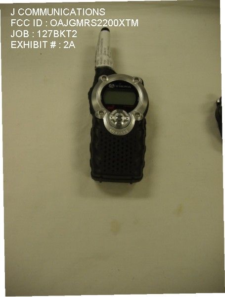
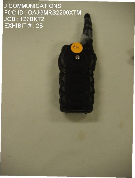
OAJGMRS2200XTMFRS/GMRS TRANSCEIVER
J Communications Co Ltd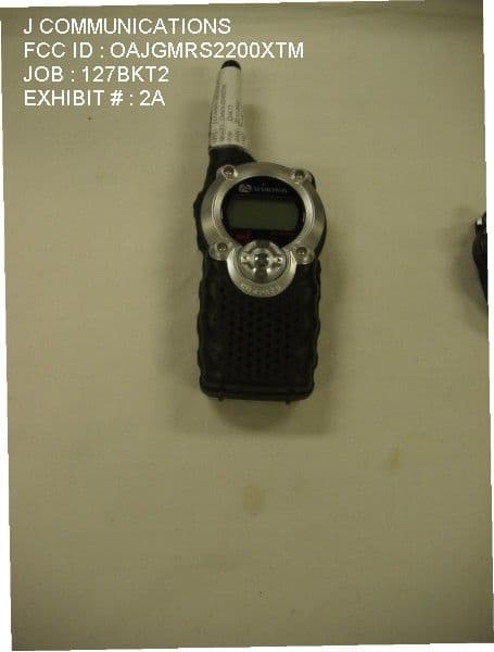
Click to zoom
Application Details
- Equipment Class
- FRF - Part 95 Family Radio Face Held Transmitter
- Date of Grant
- Jun 11, 2002
- Application Purpose
- Original Equipment
- Date of Application
- Feb 19, 2002
- Equipment Note
- FRS/GMRS TRANSCEIVER
- Frequency Range
- 462.55000000 - 462.72500000
- Company
- J Communications Co Ltd
- Country
- South Korea
Documents & Files
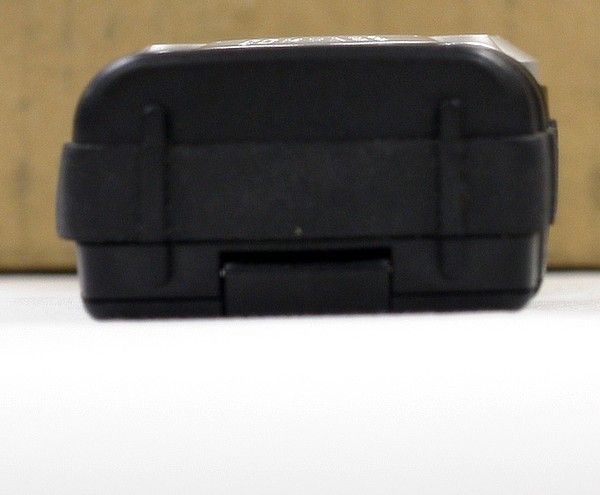
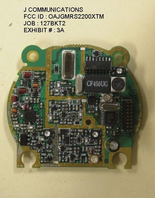
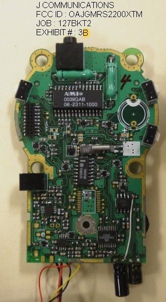
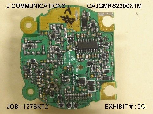
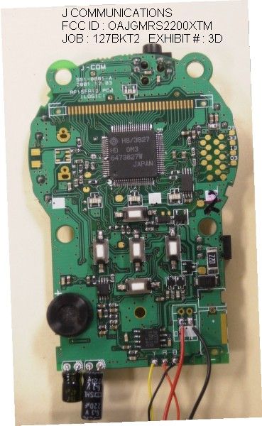
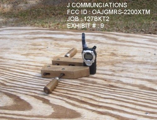
Document Text
Text extracted from the exhibit documents filed with the FCC. Open a document above to read the original.
Users Manual
3.2 Description of Icon 3.2.1 LCD ICON 1) VOX (Voice Activated Transmission) Indicator - Appears when VOX is activated. 2) Auto Scan Indicator - Icon appears when the Normal scan channel mode and Priority scan channel mode is activated. 3) Alarm Indicator - Appears when the alarm mode is on . 4) Weather Alert Indicator - Appears when the Weather alert is selected . 5) Received Signal Strength Indicator - Appears when carrier is detected in the two way mode. 6) Key Lock Indicator - Appears when the key lock mode is activated. - 7) Channel Position Indicator CH - Appears when the two way mode is displayed. 8) CTCSS (Coded Tone Controlled Squelch System) Indicator CODE - Appears when the two way mode is displayed. 9) Battery Level Indicator - Icon indicates the battery charge strength with three level. - Data is not read and written when warning signal is listened and Icon is blink. 10) RF Power AUTO / LOW Indicator < SETUP MANU > PWR AUTO - In the use of default When the power on state. (1~7CH,GMRS:2W /8~14CH,FRS:0.5W /15~22CH,GMRS:2W) PWR LOW - In the use of Only 0.5W for manual. (1~22CH,GMRS/FRS:0.5W ) 3.2.2 Description of Button function 1. Power Button(1) - To turn the Unit ON, press and hold the Power Button(1). - To turn the Unit OFF, press and hold the Power Button(1) for more than 1, 2 second. 2. UP(5) or DOWN(6) Button - Pressing the UP(5) or DOWN(6) Button in stand by mode, Volume is increased and decreased. - Pressing the UP(5) or DOWN(6) Button in Menu mode allow you to change the setting of menu. 3. Mode(4) Button - Pressing the Mode(4) Button allow you to change the mode. - If you press the Mode(4) Button during approximately two second, Lock function for menu button is operated and Key Lock Indicator is displayed in LCD monitor. - To release lock function, press and hold Mode(4) Button for more than 2 second. 4. Menu(2, 3) Button - Pressing the Menu(2, 3) Button allow you to select next menu in function edit mode. But this Button function is different in Stopwatch mode. It’s functions are Start/Stop/Clear. 5. PTT (Push-To-Talk) Button(8) - Pressing the PTT Button(8), Voice signal is transfer to the other unit, Red LED above LCD monitor(13) and Transmission icon(T) in LCD monitor(13) is lighted. - Removing your finger, the unit stops transmission and return to the receiving stand by mode. - You can transmit a call signal and unit name by double I PTT Button(8) Keying. Unit name is changed in SETUP Mode. 6. Monitor Button(7) - Pressing the Monitor Button(7) allow you to hear received signal in the current channel. - Pressing the Monitor Button(7) for more than 3 second allow you to hear beep tone and received signal in the present channel continuously. And Pressing the Monitor Button(7) releases the auto monitoring. 7. EXTERNAL Mic/Speaker(9) 3) SCAN selection Pressing the menu button(2, 3) in the Channel/Code Selection menu allows you to enter the Scan Selection menu with key beeping. Pressing the up/down button(5, 6) in the Scan Selection mode allows you to select Off, Normal scan or Priority scan while icon is blinking. If you select the Normal scan, it starts to scan the channel from the current channel. If you select the priority scan, it scans the current channel and priority channel in turn. You can select Priority channel in setup mode. 4) VOX(Voice Activated Transmission) selection Pressing the menu button(2, 3)in the Scan Selection menu allows you It enter VOX selection mode with key beeping. Pressing the up/down button(5, 6) in the VOX Selection mode allows you to select Off/Hi/Mid/Low while icon is blinking. No pressing PTT button(8), You can communicate voice to the other unit using mic or ear mic. If VOX function is selection, icon( ) is ligthed. 5) RF POWER AUTO / Low selection Pressing the menu button(2, 3)in the VOX Selection menu allows you It Enter PWR AUTO selection mode with key beeping. Pressing the up/down button(5, 6) in the PWR Selection mode allows you To select PWR AUTO,LOW . 3.3-2 FM RADIO MODE This mode is composed of 4 menu and received FM broadcasting. - FM Seek Scan : Auto selection - FM Fine Tune : Passive selection - FM Preset Memory : Broadcasting frequency memory - FM only or Two Way : FM or GMRS selection 1) FM Seek Scan Pressing the menu button (3) in the FM standby display allows you to enter FM seek menu and you can scan the FM radio frequency by using the up/down button(5, 6). If an active broadcast signal is detected, it receives a signal in that channel. 2) FM Fine Tune Pressing the menu button (3) in the FM seek menu allows you to enter FM tuning menu. You can increase and decrease FM broadcast frequency by 100 Hz using the up/down button(5, 6). 3) FM Preset Memory Pressing the menu button (3) in the FM Fine menu, “MEM OFF” is displayed on LCD monitor. And then Pressing the up/down button(5, 6) allows you to select “MEM ON”, then press the Menu button(3). If that is so, “M1 87.5” is displayed and “1” blinks. It means that broadcast channel of 87.5MHz is memorized in Memory 1. You can memory 9 broadcast channel. If you want to memory broadcast channel of 99.5MHz in Memory 5, select 5 by using the up/down button(5, 6). And then pressing the menu button(3) allows you to do auto selection or passive selection. 4) FM only or Two way Pressing the menu button (3) in the FM preset menu allows you to enter FM selection menu. You can select one of FM OFF/FM WAY by using the up/down button(5, 6) . If “OFF” is selected, you cannot receive GMRS but receive FM radio in the FM mode. And so you cannot receive FM radio but receive GMRS in others mode. If “WAY” is selected, you can receive FM radio in all modes, except for unit’s transmission or reception 3.3-3 WEATHER MODE Pressing the function key(4) in the FM MODE allows you to enter weather Radio mode shows weather channel operation status after 1 second. 1) Weather Channel Selection menu Pressing the menu key (left/right arrow key) in the Weather standby allows you to enter Weather Channel Select…
Text truncated - open the document above for the full version.
Block Diagram
6.2 Logic Diagram
Cover Letter(s)
TIMCO ENGINEERING INC. 849 NW State Road 45 Newberry, Florida 32669 888.472.2424 F 352.472.2030 email: [email protected] May 21, 2002 Ms. Diane Poole Federal Communications Commission Authorization and Evaluation Division 7435 Oakland Mills Road Columbia, MD 21046 Ref: J COMMUNICATIONS CO., LTD.’S FCC ID: OAJGMRS2200XTM CONFIRMATION # EA336364, CORRESPONDENCE ID # EA336364, Dear Ms. Poole: With regards to your request of 4/25/02, I have uploaded a new SAR report including plots, photos, and data. In addition, the manufacturer has responded to your email as follows: 1) Procedures, diagrams, and photographs of how power was measured during SAR testing. ==> The Conducte d RF powe r was me as ure d by RF Powe r me te r as attache d photograph. 2) Justification of the validity of the SAR measurement. A large drift of .5 dB in SAR was detected from the SAR plots which violates your procedure as stated in section 8.3.4 of the SAR report. As part of the justification please provide power versus time data covering at least 30 minutes. Please also state approximate SAR measurement time. ==> We 've re vise d our proce dure for drift in se ction 8.3.4 of the SAR report and checked the Conducted RF power versus time for 40 minutes. Please find the test result as attached file. 3) Revised SAR report. Please revise the statements regarding SAR limits. The General Population limit not Occupational is appropriate for a GMRS/FRS combination transceiver. ==> We 've re vise d SAR re port. Please find the SAR limit as attached file. 4) Additional SAR test data using at least 3 sets of AA batteries made by different vendors. Testing at the highest SAR location for both head and body is considered sufficient. Also, provide new body data using the speaker/microphone mentioned. ==> We 've re te ste d the above mode l wit h t hree ve ndors of AA batte rie s. Please find the SAR test data as attached file. 5) New system validation data. Supplement C requires validation within 100 MHZ of the device center frequency. ==> Unfort unate ly, we don't have 450MHz dipole antenna till now. So, we've contacted SPEAG through DYMSTEC, which is Korea Agency for getting 450MHz dipole antenna as soon as possible. Please refer to the attached Quotation sheet issued by DYMSTEC for 450MHz dipole antenna. In this time, we can only use 835MHz dipole antenna for validation. So, we've revised validation result with new 835MHz head conversion factor as attached file. FYI It appears that an incorrect probe conversion factor was used for your validation performed at 835 MHZ in head liquid. It also appears that the wrong target value was inserted in your report for the 835 MHZ verification. Values different from the SPEAG documentation. 6) Statement of tissue liquid depth. It appears from the photograph to be less then the 15 cm required by Supplement C. In the future please provide Z axis SAR scans to verify tissue depth. ==> We 've re vise d te st re port for tissue liquid de pt h. Please find the statement in the test report as attached file. 7) New uncertainty budget utilizing the draft P1528 template. ==> We 've contacte d SPEAG and re ce ive d the unce rtainty. Please find the result in the test report as attached file . Should you have any questions or require any further information, please advise. Regards, Sharon Hoffman
Operational Description
5. DESCRIPTION OF RADIO CIRCUIT 5.1 Frequency synthesizer Frequency synthesizer consists of VCO, PLL IC (built in PRESCALER) and loop filter. ( the same of FM Radio ) a) GM1500XTM VCO VCO is composed of ONE VCO. Oscillation circuit takes colpitts circuit Using variable Diode. And VCO is composed of D8, Q6, C38, C35, L16, C31, VC2, C28, C29. VCO control voltage through loop filter adjusts frequency and Microphone signal through Modulation terminal makes modulation. b) FM Radio VCO FM VCO is composed of ONE VCO. Oscillation circuit takes colpitts circuit Using variable Diode. And VCO is composed of D10, C132, L23, C128, C129. VCO control voltage of through loop filter adjusts frequency. d) PLL IC (with FM Radio) PLL IC is adjustable IC to produce the wished frequency which VCO Provides through loop filter. TB31202FN is one packaging two systems prescaler and PLL for receiver and Transmitter. It has internal counter using 21.25MHz reference frequency to make 6.25KHz As reference Signal. GM1500XTM VCO is selected of U4A analog switch, and then PLL IC Output Port(pin14) is same. Only FM Radio VCO is used other output Port(pin3) of PLL IC. VCO frequency from prescaled input is divided signal is compared with Reference Signal phase in phase comparator. Built-in charger pump changes voltage (until two signals are in phase) and charged voltage supplies VCO through loop filter to produce the desired Frequency. Frequency data associated with channel goes to PLL IC by CPU through CLOCK DATA. PLL IC enables by STB line of CPU. e) Loop Filter (with FM Radio) Loop filter is composed of R25,R26,C42,C43. (FM Radio: R80,R81,C133,C134). And DC voltage with pulse is supplied from 14 pin of PLL IC. At that time Loop filter eliminates harmonic component in pulse. It helps VCO,FM Radio VCO oscillate clearly as DC voltage is supplied into Varicap. 5.2 RECEIVER This is composed of Dual Conversion Super Heterodyne. First IF is 21.7MHz. Local oscillator frequency is lower in 1’st IF than Rx frequency. It called Low side injection. Second IF is 450kHz. 2 nd local oscillator frequency comes to 21.25MHz. GM1500XTM and NOAA is capable of Dual Conversion Super Heterodyne, But FM Radio is only U3 used. a) RX /TX /FM Radio Conversion Circuit Rx signal goes to Rx/Tx/FM Radio Rx conversion circuit through FIXED Antenna connector, low pass filter(L1,L2,L3,L4,C2,C3,C4,C5) and PM1500XTM Receiver resonance circuit composed of L10,C64. And FM Radio receiver resonance circuit composed Of L11,C136 . when transmitting, voltage through R1,L21, D2 supplies,D3.D4 of Receive input is short and Tx is on condition. When PIN diode is off in condition of Rx, L10 and C64 resonate serially and make impedance matching at receiver. When the FM Radio mode, C136,L11 make impedance matching, and the other Circuit is VCC off(except for system VCC). b) Front-End (GM1500XTM, FM Radio ) Front-End has Q7 to provide a high sensitivity and low noise feature. It employs Saw filter as band pass filter to eliminate image frequency and to Produce enough pass band by Q7 input and output. FM Radio Front-End is composed of Q20,L11,C136. c) Mixer (GM1500XTM) Mixer has one base BFQ 67W(Q9) to feature high low noise Feature high Low noise quality. FM Radio is not mixer and audio signal is output of U3 pin14. It has RF signal through L1, L10, SF1 and Q7 RF signal from Local oscillator mixed. It develops 1'st IF 21.7MHz. 1’st IF goes to 1’st IF amplifier Q10 (2SC4083) Base through X-tal filter XF1. IF of mixing signals is selected and taken into X-tal filter.output impedance Of mixer is direct matched with input impedance of X-tal filter. Matching of filter satisfies pass bandwidth of filter, ripple elimination with In pass band, and attenuation characteristic of stop band. X-tal filter is composed of two pole monolithic X-tal filter,8KHz of IF band- Width 8kHz of IF bandwidth R48 is used as impedance matching with 1'st IF Amp Q10. d) IF AMP and Detection (GM1500XTM) 1'st IF AMP Q10 supplies IF (U2) mixer input pin16 through output resistor R50 And C89 to need gain in insertion loss of X-tal filter and last stage circuit. Multi-use IF IC makes up of mixer IF AMP. Pin 2 nd local frequency enter to pin1. It supplies mixer of internal IC. Mixer output of IC through pin3 passes 450KHz Ceramic filter, supplies 2 nd IF amplifier and limits. After 2 nd IF AMP has a process of enough gain and AM rejection, it comes to Quadrature detection. Demodulated audio signal by T1(Quad Coil) is amplified And Comes out to pin9. Detected audio signal through R58, C96 and input in audio amp.IC U215 through C97. e) Squelch Circuit ( GM1500XTM ) Noise component of detected outputs has amplification squelch threshold is con- trolled by Resistor R55,C94,R51,C95,VR1. Squelch is not operating FM Radio mode. f) Audio Amplifier ( GM1500XTM , FM Radio ) Demodulated audio signal enters to pin3 of U215. After above signal amplies in U215 pin5 through C243. It comes out to pin5 Then, It reaches at speaker. 5.3 Transmitter When Tx develops with pressing PTT switch, VCO output amplifies through Q1,Q2 Transmits by antenna through low pass filter. Tx RF signal produced from Tx VCO is amplified by DRIVER Q2 through C15 and Entered Q1 POWER TR input terminal with final amplification. After this stage, The signal is emitted at antenna through 50 matching circuit to lowpass filt- er (L1,L2,L3,L4,C2,C3,C4,C5) to eliminate harmonic. 5.3-1 Audio Modulation and Audio Amplification Audio signal produced by external or internal microphone, limits amplification By IC U206A,206B. It enters to VCO modulation circuit through scrambler IC(U210) And tone IC(U202). And 3KHz low pass filter(U207A). Max Frequency deviation is adjusted by VR2 keeps noise and audio from entering To VCO at time of TX. Audio modulation and Audio Amplification has characteristic of 6dB/OCT Pre-emphasis by U207B. 5.4 TEMPERATURE CIRCUIT Temperature circuit is composed of U209(S-8120ANP). It is transfer of CPU for sensing temperature from ind…
Text truncated - open the document above for the full version.
RF Exposure Info
HYUNDAI CALIBRATION & CERTIFICATION TECH. CO., LTD. PRODUCT COMPLIANCE DIVISION SAN 136-1, AMI-RI , BUBAL-EUP, ICHEON-SI, KYOUNGKI-DO, 467-701, KOREA TEL : +82 31 639 8518 FAX : +82 31 639 8525 CERTIFICATE OF COMPLIANCE (SAR EVALUATION) EUT Type: General Mobile Radio Service(GMRS) –Transceiver Model(s): GMRS-2200XTM Tx Frequency: 462.5500 MHz – 462.7250 MHz (GMRS) 467.5625 MHz – 467.7125 MHz (FRS) Max. SAR Measurement(s): 1.020mW/g(1g) GMRS Face SAR ; 1.345mW/g(1g) GMRS Body SAR Max. RF Output Power: 2.134W ERP(33.3dBm) Emission Designator: 9K5F3E Channel Capacity: 22 Application Type: Certification Trade Name(s): J COM FCC Rule Part(s): 95(A), 2(J) Hyundai C-Tech Co., Ltd. Certifies that no party to this application has been denied FCC benefits pursuant to section 5301 of the Anti- Drug Abuse Act of 1998, 21 U.S. C. 853(a) Report prepared by : Ki-Soo Kim Manager of Product Compliance Team This report only responds to the tested sample and may not be reproduced, except in full, without written approval of the HCT Co., J COMMUNICATIONS CO., LTD. 124-4 Ojeon-Dong, Uiwang-City, Kyungki-Do, KOREA FRN: 0005- 8390- 59 Date of Issue: April 4, 2002 Test Report No.: HCT-SAR02-0401 Test Site: HYUNDAI CALIBRATION & CERTIFICATION TECHNOLOGIES CO., LTD. FRN: 0005-8642- 21 FCC ID : APPLICANT : OAJGMRS2200XTM J COMMUNICATIONS CO., LTD. Report No.: HCT-SAR02-0401 FCC ID : OAJGMRS2200XTM DATE : April 4, 2002 HYUNDAI CALIBRATION & CERTIFICATION TECHNOLOGIES CO., LTD. SAN 136-1, AMI-RI , BUBAL-EUP, ICHEON-SI,KYOUNKI-DO, 467-701,KOREA TEL : +82 31 639 8518 FAX : +82 31 639 8525 www.hctec.co.kr Ltd. Table of Contents 1.1 SCOPE ---------------------------------------------------------------------------------------------------------- 2.1 INTRODUCTION / SAR DEFINITION --------------------------------------------------------------------- 3.1 SAR MEASUREMENT SET-UP --------------------------------------------------------------------------- 4.1 E-FIELD PROBE SYSTEM --------------------------------------------------------------------------------- 5.1 E-FIELD PROBE CALIBRATION PROCESS -------------------------------------------------------- 6.1 PHANTOM, HOLDER, & EQUIVALENT TISSUE --------------------------------------------------- 7.1 SYSTEM SPECIFICATIONS ------------------------------------------------------------------------------ 8.1 MEASUREMENT PROCESS ------------------------------------------------------------------------------ 9.1 ANSI/ IEEE C95.1 - 1992 RF EXPOSURE LIMITS -------------------------------------------------------- 10.1 MEASUREMENT UNCERTAINTIES ------------------------------------------------------------------- 11.1 TEST DATA SUMMARY ---------------------------------------------------------------------------------- 12.1 SAR TEST EQUIPMENT LIST --------------------------------------------------------------------------- 13.1 CONCLUSION ------------------------------------------------------------------------------------------------ 14.1 REFERENCES -------------------------------------------------------------------------------------------- APPENDIX A – SAR TEST PLOTS APPENDIX B – TEST SETUP PHOTOGRAPHS APPENDIX C – EUT PROFILE PHOTOGRAPHS APPENDIX D – DIPOLE VALIDATION PLOTS APPENDIX E – PROBE CALIBRATION DATA APPENDIX F – DIPOLE CALIBRATION DATA 3 4 5 6-7 8 9 10 11 12 13 14 15-16 17 18 Report No.: HCT-SAR02-0401 FCC ID : OAJGMRS2200XTM DATE : April 4, 2002 HYUNDAI CALIBRATION & CERTIFICATION TECHNOLOGIES CO., LTD. SAN 136-1, AMI-RI , BUBAL-EUP, ICHEON-SI,KYOUNKI-DO, 467-701,KOREA TEL : +82 31 639 8518 FAX : +82 31 639 8525 www.hctec.co.kr SAR MEASUREMENT REPORT 1.1 SCOPE Environmental evaluation measurements of specific absorption rate 1 (SAR) distributions in emulated human head and body tissues exposed to radio frequency(RF) radiation from wireless portable devices for compliance with the rules and regulations of the U.S. Federal Communications Commission (FCC).2 1. 2 Applicant • FCC ID: OAJGMRS2200XTM • EUT Type: General Mobile Radio Service(GMRS) –Transceiver • Trade Name: J COM • Model(s): GMRS-2200XTM • Tx Frequency: 462.5500 MHz – 462.7250 MHz (GMRS) 467.5625MHz – 467.7125 MHz (FRS) • Application Type: Certification • Classification: Licensed Portable Transmitter • Modulation(s): FM • Max SAR Measurement: 1.020mW/g(1g) GMRS Face SAR ; 1.345mW/g(1g) GMRS Body SAR • Max. RF Output Power: 2.134W ERP(33.3dBm) • Power Supply: (x4) AAA Alkaline batteries (1.5VDC) • Place of Test(s): Hyundai C- TECH. EMC Lab. • Date(s) of Tests: March 12, 2002 / March 13, 2002 Figure 1. SAR System • Report No.: HCT-SAR02-0401 1 Specific Absorption Rate (SAR) is a measure of the rate of energy absorption due to exposure to an RF transmitting source (wireless portable device). 2 IEEE/ANSI Std. C95.1-1992 limits are used to determine compliance with FCC ET Docket 93-62 Company Name: J COMMUNICATIONS CO., LTD. Address: 124-4 Ojeon-Dong, Uiwang-City, Kyungki-Do, KOREA Attention: MR. GS OH – Marketing Manager Tel. / Fax : 82- 31- 428- 2221 / 82- 451- 2994 E-Mail : [email protected] Report No.: HCT-SAR02-0401 FCC ID : OAJGMRS2200XTM DATE : April 4, 2002 HYUNDAI CALIBRATION & CERTIFICATION TECHNOLOGIES CO., LTD. SAN 136-1, AMI-RI , BUBAL-EUP, ICHEON-SI,KYOUNKI-DO, 467-701,KOREA TEL : +82 31 639 8518 FAX : +82 31 639 8525 www.hctec.co.kr 2.1 INTRODUCTION The FCC has adopted the guidelines for evaluating the environmental effects of radio frequency radiation in ET Docket 93-62 on Aug. 6, 1996 to protect the public and workers from the potential hazards of RF emissions due to FCC-regulated portable devices.[1] The safety limits used for the environmental evaluation measurements are based on the criteria published by the American National Standards Institute (ANSI) for localized specific absorption rate (SAR) in IEEE/ANSI C95.1-1992 Standard for Safety Levels with Respect to Human Exposure to Radio Frequency Electromagnetic Fields, 3 kHz to 300 GHz. (c) 1992 by the Institute of Electrical and Electronics Engineers, Inc., New …
Text truncated - open the document above for the full version.
RF Exposure Info
Report No.: HCT-SAR02-0401 FCC ID : OAJGMRS2200XTM DATE : April 4, 2002 HYUNDAI CALIBRATION & CERTIFICATION TECHNOLOGIES CO., LTD. SAN 136-1, AMI-RI , BUBAL-EUP, ICHEON-SI,KYOUNKI-DO, 467-701,KOREA TEL : +82 31 639 8518 FAX : +82 31 639 8525 www.hctec.co.kr APPENDIX A – SAR TEST PLOTS Report No.: HCT-SAR02-0401 FCC ID : OAJGMRS2200XTM DATE : April 4, 2002 HYUNDAI CALIBRATION & CERTIFICATION TECHNOLOGIES CO., LTD. SAN 136-1, AMI-RI , BUBAL-EUP, ICHEON-SI,KYOUNKI-DO, 467-701,KOREA TEL : +82 31 639 8518 FAX : +82 31 639 8525 www.hctec.co.kr Report No.: HCT-SAR02-0401 FCC ID : OAJGMRS2200XTM DATE : April 4, 2002 HYUNDAI CALIBRATION & CERTIFICATION TECHNOLOGIES CO., LTD. SAN 136-1, AMI-RI , BUBAL-EUP, ICHEON-SI,KYOUNKI-DO, 467-701,KOREA TEL : +82 31 639 8518 FAX : +82 31 639 8525 www.hctec.co.kr Report No.: HCT-SAR02-0401 FCC ID : OAJGMRS2200XTM DATE : April 4, 2002 HYUNDAI CALIBRATION & CERTIFICATION TECHNOLOGIES CO., LTD. SAN 136-1, AMI-RI , BUBAL-EUP, ICHEON-SI,KYOUNKI-DO, 467-701,KOREA TEL : +82 31 639 8518 FAX : +82 31 639 8525 www.hctec.co.kr Report No.: HCT-SAR02-0401 FCC ID : OAJGMRS2200XTM DATE : April 4, 2002 HYUNDAI CALIBRATION & CERTIFICATION TECHNOLOGIES CO., LTD. SAN 136-1, AMI-RI , BUBAL-EUP, ICHEON-SI,KYOUNKI-DO, 467-701,KOREA TEL : +82 31 639 8518 FAX : +82 31 639 8525 www.hctec.co.kr Report No.: HCT-SAR02-0401 FCC ID : OAJGMRS2200XTM DATE : April 4, 2002 HYUNDAI CALIBRATION & CERTIFICATION TECHNOLOGIES CO., LTD. SAN 136-1, AMI-RI , BUBAL-EUP, ICHEON-SI,KYOUNKI-DO, 467-701,KOREA TEL : +82 31 639 8518 FAX : +82 31 639 8525 www.hctec.co.kr Report No.: HCT-SAR02-0401 FCC ID : OAJGMRS2200XTM DATE : April 4, 2002 HYUNDAI CALIBRATION & CERTIFICATION TECHNOLOGIES CO., LTD. SAN 136-1, AMI-RI , BUBAL-EUP, ICHEON-SI,KYOUNKI-DO, 467-701,KOREA TEL : +82 31 639 8518 FAX : +82 31 639 8525 www.hctec.co.kr Report No.: HCT-SAR02-0401 FCC ID : OAJGMRS2200XTM DATE : April 4, 2002 HYUNDAI CALIBRATION & CERTIFICATION TECHNOLOGIES CO., LTD. SAN 136-1, AMI-RI , BUBAL-EUP, ICHEON-SI,KYOUNKI-DO, 467-701,KOREA TEL : +82 31 639 8518 FAX : +82 31 639 8525 www.hctec.co.kr Report No.: HCT-SAR02-0401 FCC ID : OAJGMRS2200XTM DATE : April 4, 2002 HYUNDAI CALIBRATION & CERTIFICATION TECHNOLOGIES CO., LTD. SAN 136-1, AMI-RI , BUBAL-EUP, ICHEON-SI,KYOUNKI-DO, 467-701,KOREA TEL : +82 31 639 8518 FAX : +82 31 639 8525 www.hctec.co.kr Report No.: HCT-SAR02-0401 FCC ID : OAJGMRS2200XTM DATE : April 4, 2002 HYUNDAI CALIBRATION & CERTIFICATION TECHNOLOGIES CO., LTD. SAN 136-1, AMI-RI , BUBAL-EUP, ICHEON-SI,KYOUNKI-DO, 467-701,KOREA TEL : +82 31 639 8518 FAX : +82 31 639 8525 www.hctec.co.kr Report No.: HCT-SAR02-0401 FCC ID : OAJGMRS2200XTM DATE : April 4, 2002 HYUNDAI CALIBRATION & CERTIFICATION TECHNOLOGIES CO., LTD. SAN 136-1, AMI-RI , BUBAL-EUP, ICHEON-SI,KYOUNKI-DO, 467-701,KOREA TEL : +82 31 639 8518 FAX : +82 31 639 8525 www.hctec.co.kr Report No.: HCT-SAR02-0401 FCC ID : OAJGMRS2200XTM DATE : April 4, 2002 HYUNDAI CALIBRATION & CERTIFICATION TECHNOLOGIES CO., LTD. SAN 136-1, AMI-RI , BUBAL-EUP, ICHEON-SI,KYOUNKI-DO, 467-701,KOREA TEL : +82 31 639 8518 FAX : +82 31 639 8525 www.hctec.co.kr Report No.: HCT-SAR02-0401 FCC ID : OAJGMRS2200XTM DATE : April 4, 2002 HYUNDAI CALIBRATION & CERTIFICATION TECHNOLOGIES CO., LTD. SAN 136-1, AMI-RI , BUBAL-EUP, ICHEON-SI,KYOUNKI-DO, 467-701,KOREA TEL : +82 31 639 8518 FAX : +82 31 639 8525 www.hctec.co.kr Report No.: HCT-SAR02-0401 FCC ID : OAJGMRS2200XTM DATE : April 4, 2002 HYUNDAI CALIBRATION & CERTIFICATION TECHNOLOGIES CO., LTD. SAN 136-1, AMI-RI , BUBAL-EUP, ICHEON-SI,KYOUNKI-DO, 467-701,KOREA TEL : +82 31 639 8518 FAX : +82 31 639 8525 www.hctec.co.kr APPENDIX B – EUT TEST SETUP PHOTOGRAPHS Report No.: HCT-SAR02-0401 FCC ID : OAJGMRS2200XTM DATE : April 4, 2002 HYUNDAI CALIBRATION & CERTIFICATION TECHNOLOGIES CO., LTD. SAN 136-1, AMI-RI , BUBAL-EUP, ICHEON-SI,KYOUNKI-DO, 467-701,KOREA TEL : +82 31 639 8518 FAX : +82 31 639 8525 www.hctec.co.kr Report No.: HCT-SAR02-0401 FCC ID : OAJGMRS2200XTM DATE : April 4, 2002 HYUNDAI CALIBRATION & CERTIFICATION TECHNOLOGIES CO., LTD. SAN 136-1, AMI-RI , BUBAL-EUP, ICHEON-SI,KYOUNKI-DO, 467-701,KOREA TEL : +82 31 639 8518 FAX : +82 31 639 8525 www.hctec.co.kr Report No.: HCT-SAR02-0401 FCC ID : OAJGMRS2200XTM DATE : April 4, 2002 HYUNDAI CALIBRATION & CERTIFICATION TECHNOLOGIES CO., LTD. SAN 136-1, AMI-RI , BUBAL-EUP, ICHEON-SI,KYOUNKI-DO, 467-701,KOREA TEL : +82 31 639 8518 FAX : +82 31 639 8525 www.hctec.co.kr Report No.: HCT-SAR02-0401 FCC ID : OAJGMRS2200XTM DATE : April 4, 2002 HYUNDAI CALIBRATION & CERTIFICATION TECHNOLOGIES CO., LTD. SAN 136-1, AMI-RI , BUBAL-EUP, ICHEON-SI,KYOUNKI-DO, 467-701,KOREA TEL : +82 31 639 8518 FAX : +82 31 639 8525 www.hctec.co.kr APPENDIX C – EUT PROFILE PHOTOGRAPHS Report No.: HCT-SAR02-0401 FCC ID : OAJGMRS2200XTM DATE : April 4, 2002 HYUNDAI CALIBRATION & CERTIFICATION TECHNOLOGIES CO., LTD. SAN 136-1, AMI-RI , BUBAL-EUP, ICHEON-SI,KYOUNKI-DO, 467-701,KOREA TEL : +82 31 639 8518 FAX : +82 31 639 8525 www.hctec.co.kr Report No.: HCT-SAR02-0401 FCC ID : OAJGMRS2200XTM DATE : April 4, 2002 HYUNDAI CALIBRATION & CERTIFICATION TECHNOLOGIES CO., LTD. SAN 136-1, AMI-RI , BUBAL-EUP, ICHEON-SI,KYOUNKI-DO, 467-701,KOREA TEL : +82 31 639 8518 FAX : +82 31 639 8525 www.hctec.co.kr Report No.: HCT-SAR02-0401 FCC ID : OAJGMRS2200XTM DATE : April 4, 2002 HYUNDAI CALIBRATION & CERTIFICATION TECHNOLOGIES CO., LTD. SAN 136-1, AMI-RI , BUBAL-EUP, ICHEON-SI,KYOUNKI-DO, 467-701,KOREA TEL : +82 31 639 8518 FAX : +82 31 639 8525 www.hctec.co.kr APPENDIX D – DIPOLE VALIDATION PLOTS
RF Exposure Info
Report No.: HCT-SAR02-0401 FCC ID : OAJGMRS2200XTM DATE : April 4, 2002 HYUNDAI CALIBRATION & CERTIFICATION TECHNOLOGIES CO., LTD. SAN 136-1, AMI-RI , BUBAL-EUP, ICHEON-SI,KYOUNKI-DO, 467-701,KOREA TEL : +82 31 639 8518 FAX : +82 31 639 8525 www.hctec.co.kr Report No.: HCT-SAR02-0401 FCC ID : OAJGMRS2200XTM DATE : April 4, 2002 HYUNDAI CALIBRATION & CERTIFICATION TECHNOLOGIES CO., LTD. SAN 136-1, AMI-RI , BUBAL-EUP, ICHEON-SI,KYOUNKI-DO, 467-701,KOREA TEL : +82 31 639 8518 FAX : +82 31 639 8525 www.hctec.co.kr Report No.: HCT-SAR02-0401 FCC ID : OAJGMRS2200XTM DATE : April 4, 2002 HYUNDAI CALIBRATION & CERTIFICATION TECHNOLOGIES CO., LTD. SAN 136-1, AMI-RI , BUBAL-EUP, ICHEON-SI,KYOUNKI-DO, 467-701,KOREA TEL : +82 31 639 8518 FAX : +82 31 639 8525 www.hctec.co.kr APPENDIX E – PROBE CALIBRATION DATA Report No.: HCT-SAR02-0401 FCC ID : OAJGMRS2200XTM DATE : April 4, 2002 HYUNDAI CALIBRATION & CERTIFICATION TECHNOLOGIES CO., LTD. SAN 136-1, AMI-RI , BUBAL-EUP, ICHEON-SI,KYOUNKI-DO, 467-701,KOREA TEL : +82 31 639 8518 FAX : +82 31 639 8525 www.hctec.co.kr Report No.: HCT-SAR02-0401 FCC ID : OAJGMRS2200XTM DATE : April 4, 2002 HYUNDAI CALIBRATION & CERTIFICATION TECHNOLOGIES CO., LTD. SAN 136-1, AMI-RI , BUBAL-EUP, ICHEON-SI,KYOUNKI-DO, 467-701,KOREA TEL : +82 31 639 8518 FAX : +82 31 639 8525 www.hctec.co.kr Report No.: HCT-SAR02-0401 FCC ID : OAJGMRS2200XTM DATE : April 4, 2002 HYUNDAI CALIBRATION & CERTIFICATION TECHNOLOGIES CO., LTD. SAN 136-1, AMI-RI , BUBAL-EUP, ICHEON-SI,KYOUNKI-DO, 467-701,KOREA TEL : +82 31 639 8518 FAX : +82 31 639 8525 www.hctec.co.kr Report No.: HCT-SAR02-0401 FCC ID : OAJGMRS2200XTM DATE : April 4, 2002 HYUNDAI CALIBRATION & CERTIFICATION TECHNOLOGIES CO., LTD. SAN 136-1, AMI-RI , BUBAL-EUP, ICHEON-SI,KYOUNKI-DO, 467-701,KOREA TEL : +82 31 639 8518 FAX : +82 31 639 8525 www.hctec.co.kr Report No.: HCT-SAR02-0401 FCC ID : OAJGMRS2200XTM DATE : April 4, 2002 HYUNDAI CALIBRATION & CERTIFICATION TECHNOLOGIES CO., LTD. SAN 136-1, AMI-RI , BUBAL-EUP, ICHEON-SI,KYOUNKI-DO, 467-701,KOREA TEL : +82 31 639 8518 FAX : +82 31 639 8525 www.hctec.co.kr Report No.: HCT-SAR02-0401 FCC ID : OAJGMRS2200XTM DATE : April 4, 2002 HYUNDAI CALIBRATION & CERTIFICATION TECHNOLOGIES CO., LTD. SAN 136-1, AMI-RI , BUBAL-EUP, ICHEON-SI,KYOUNKI-DO, 467-701,KOREA TEL : +82 31 639 8518 FAX : +82 31 639 8525 www.hctec.co.kr Report No.: HCT-SAR02-0401 FCC ID : OAJGMRS2200XTM DATE : April 4, 2002 HYUNDAI CALIBRATION & CERTIFICATION TECHNOLOGIES CO., LTD. SAN 136-1, AMI-RI , BUBAL-EUP, ICHEON-SI,KYOUNKI-DO, 467-701,KOREA TEL : +82 31 639 8518 FAX : +82 31 639 8525 www.hctec.co.kr Report No.: HCT-SAR02-0401 FCC ID : OAJGMRS2200XTM DATE : April 4, 2002 HYUNDAI CALIBRATION & CERTIFICATION TECHNOLOGIES CO., LTD. SAN 136-1, AMI-RI , BUBAL-EUP, ICHEON-SI,KYOUNKI-DO, 467-701,KOREA TEL : +82 31 639 8518 FAX : +82 31 639 8525 www.hctec.co.kr Report No.: HCT-SAR02-0401 FCC ID : OAJGMRS2200XTM DATE : April 4, 2002 HYUNDAI CALIBRATION & CERTIFICATION TECHNOLOGIES CO., LTD. SAN 136-1, AMI-RI , BUBAL-EUP, ICHEON-SI,KYOUNKI-DO, 467-701,KOREA TEL : +82 3…
Text truncated - open the document above for the full version.
Contact Information
Applicant
C H YOO(Assistant Manager)
Technical Contact
Timco Engineering, Inc.Mario R de Aranzeta
[email protected]888-472-2424
849 NW State Road 45 · Newberry, Florida · United States
Non-Technical Contact
Timco Engineering, Inc.Sharon A Hoffman
[email protected]888-472-2424
Test Firm
Timco Engineering, Inc.S Sanders
Technical Specifications
| # | Rule Parts | Frequency Range | Power Output | Emission | Tolerance |
|---|---|---|---|---|---|
| 2 | 95A | 462.55 MHz - 462.725 MHz | 2 W | 10K5F3E | 5 ppm |
Other Applications from J Communications Co Ltd
OAJBGP2000
Dec 13, 2004Bluetooth GPS Receiver
Equipment Class
DTS - Digital Transmission System
OAJBAG-1000
May 29, 2003Bluetooth Audio Gateway
Equipment Class
DSS - Part 15 Spread Spectrum Transmitter
OAJBH-1000
Dec 29, 2002Bluetooth Headset
Equipment Class
DSS - Part 15 Spread Spectrum Transmitter
OAJBAG-2000
Dec 29, 2002Bluetooth Audio Gateway
Equipment Class
DSS - Part 15 Spread Spectrum Transmitter
OAJBA-1000U
Dec 23, 2002Bluetooth USB Dongle
Equipment Class
DSS - Part 15 Spread Spectrum Transmitter