OAM1023018
Corrisoft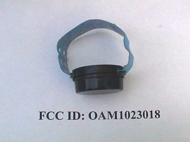
Click to zoom
Application Details
- Equipment Class
- DSC - Part 15 Security/Remote Control Transmitter
- Date of Grant
- Sep 06, 1999
- Application Purpose
- Original Equipment
- Date of Application
- May 26, 1999
- Frequency Range
- 303.82500000 - 303.82500000
- Company
- Corrisoft
- Country
- United States
Documents & Files

Document Text
Text extracted from the exhibit documents filed with the FCC. Open a document above to read the original.
Users Manual
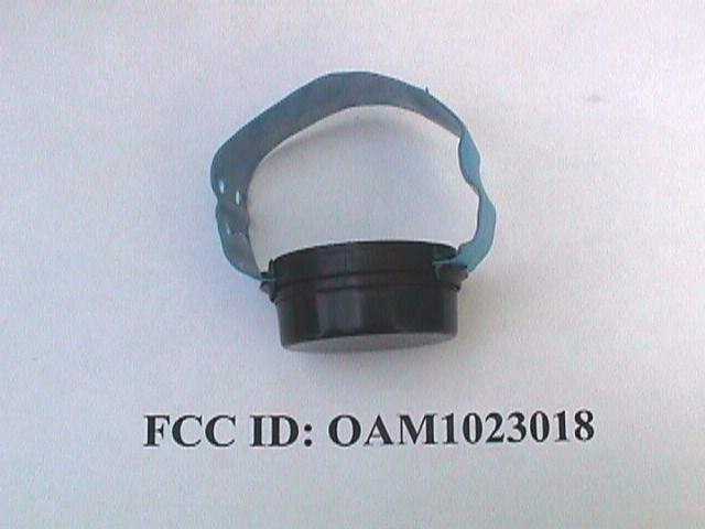
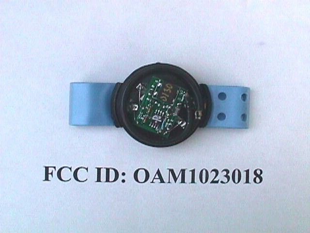
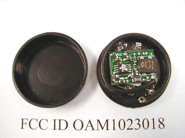
Page 1 of 4 Rev. 1.01 5/21/99 wc Operating manual for Wireless Cuff .doc Operation manual for the 1023018 wireless transmitter Wireless Cuff Preparation: The wireless cuff includes five components, a battery assembly (hub), “O” ring, transmitter assembly, a bracelet and four screws. (See figure 1) • Battery Assembly - Provides a nominal 6 Volt DC source to power the transmitter when assembled. Life is estimated at 3 months average. The transmitter will cease operation at around 3.9 Volts. • “O” Ring - Seals the transmitter compartment when assembled making it waterproof. • Transmitter Assembly - Encapsulated transmitter with battery contacts for power. Periodically sends a message to the receiver which is resident in the PTU. • Screws, 4 each - #4 Phillips, flat head, stainless steel, sheet metal screws; 3/8” in length. A cuff may be attached to a client once preparation has been completed. Select an appropriate length bracelet for the ankle (table 1), one battery assembly with “O” ring installed, one transmitter assembly and four screws. Sizes 5,6,7 and 8 are stocked by ABS. Other sizes will have to be special ordered at the time of contract. Lead time is two weeks. # of holes Ankle Circumference # of Holes Ankle Circumference 2 6.5” 7 9.0” 3 7.0” 8 9.5” 4 7.5” 9 10.0” 5 8.0” 10 10.5” 6 8.5” 11 11.0” Table 1 Assemble Transmitter and Battery: Align the battery assembly key appropriately with the transmitter assembly slot and lightly engage the hub of the battery assembly to the transmitter cavity. Rotate one assembly carefully until the index mark on one aligns with the index mark on the other. Press the two assemblies together firmly with both hands until little gap can be observed between the two assemblies. Hold them in place with one hand and insert one screw (using a Phillips screwdriver) at a time. Insert the second screw 180 degrees from the first and tighten. The other two screws may be inserted in any order. Wireless Bracelet Installation: Figure 2 provides the necessary client installation instructions. Install the bracelet to one side of the cuff assembly first. The second side is installed while against the clients wrist or ankle. Once the cuff is installed on the client it must be activated. Activation occurs when the magnet provided is placed against the transmitter body for a minimum of five seconds. Once activated the client is free to move within the limits of the following violation definitions. Page 2 of 4 Rev. 1.01 5/21/99 wc Operating manual for Wireless Cuff .doc • Proximity - Occurs when the client, wearing the cuff, moves away from the PTU between 20 ft. outdoors or 30 ft indoors. To be detected as a cuff violation the client must outside these limits for a minimum of for 30 minutes. This violation rearms itself if an individual moves back inside these limits after being out for 30 minutes. • Cuff violation - Occurs when a client forcibly removes or cuts the bracelet from the transmitter. This violation will not page again until the bracelet has been replaced and the cuff has been rearmed (minimum of 10 seconds) with the rearming tool. Cautions • After rearming is complete the client must stay within the proximity limits for 5 minutes. Premature movement outside these limits may prevent a cuff violation from being detected. • Metal obstructions, in the line of sight between the cuff and the PTU, such as metal filing cabinets, walls or refrigerators can result in false proximity violations. Figure 1 Transmitter Battery “O” ring Screws used to attached battery to transmitter FCC identifier location. Page 3 of 4 Rev. 1.01 5/21/99 wc Operating manual for Wireless Cuff .doc ALIGNMENT PIN GROOVE INDEX TAB INDEX TAB ALIGNMENT PIN TITLEFigure 2 - Wireless cuff 1. Install O-Ring over battery hub. 2. Align the index tabs and press to mate the two sections. DO NOT TWIST to align the index tabs. If the tabs are not aligned, pull the sections apart and re- seat. Sections WILL NOT MATE if the alignment pin is not seated in the alignment pin groove. 3. Using a #1 phillips screwdriver, install the four screws. 4. Install the cuff strap. Make sure the metal tab on the cuff strap will contact the metal contact in the transmitter assembly and push the cuff tab into a recess of the transmitter assembly. Loop the strap around the arm or leg, holding the transmitter assembly with the screws (battery section) against the arm or leg, and snap the other end of the cuff strap into place. O-RING SCREW 4 EA STRAP ASSY BATTERY TRANSMITTER BATTERY HUB Page 4 of 4 Rev. 1.01 5/21/99 wc Operating manual for Wireless Cuff .doc FCC Label Exhibit The transmitter is too small to place the label on it. The FCC ID number will be stamped into the plastic case. See figure one for location of stamping. There will be no serial number stamped into the case. This device complies with Part 15 of the FCC rules. Operation is subject to the following two conditions: (1) this device may not cause harmful interference, and (2) this device must accept any interference received, including interference that may cause undesired operation ABS<Comtrak Model Numbers: 1023018 Serial No.: _ _ _ FCC ID: OAM1023018 Advanced Business Sciences Made in USA
Block Diagram
Page 1 of 2 rev 1.01 4/27/99 wc Theory of operation for ABS cuff transmitter2.doc Theory of operation for ABS cuff transmitter. The following is the schematic for the transmitter which contains a program governing its transmitted serial numbers. Figure 1 B1 is consists of two lithium batteries connected in series to provide a 6V power source. C2 is a 0.1 uf capacitor providing power filtering. U2 is a RFM HX1002; 303.825MHz Hybrid transmitter using FCC part 15 approved SAW filtering. RF Output power into 50 Ω @ 25°C is –3dBm minimum and +2dBm Maximum R6 is used for current limiting on the data line between the PIC chip and the transmitter chip U1 is the 12C509 PIC chip running on an internal 4 MHz oscillator. SW1 is a magnetic switch used to force transmitter in a continuos transmission mode. Ant 1 is a 50 ohm tuned ¼ γ internal antenna D1, D2, R4, &R2 makes up the low battery detect circuitry. The following diagram shows the transmitted data stream The Data stream consists of a timing pulse followed by a data pulse. The on/off time is 500us/500us if a data pulse of “1” is transmitted and 500us/1500us if a “0” is transmitted. Page 2 of 2 rev 1.01 4/27/99 wc Theory of operation for ABS cuff transmitter2.doc The following block diagram shows the RF oscillators and data path. Figure 2: Block diagram of oscillators and data path PIC Chip with an 4MHz internal RC oscillator. RFM ASH transmitter. 303.825MH z saw resonator 1K baud max 3 1 4
ID Label/Location Info
FCC ID Label Location between detachable battery and transmitter FCC ID Label Location FCC ID: OAM1023018
ID Label/Location Info
SIGNATUREDATE DWNDATE DATE DATE DATE DATE CHK APPV APPV APPV TITLE FSCM NO SCALE REV SHEET REVISIONS ZONEREVDESCRIPTIONDATE QTYPART NODESCRIPTION A ADVANCED BUSINESS SCIENCES, INC. 3345 NORTH 107TH STREET OMAHA NE 68134 C O N F I D E N T I A L Advanced Business Sciences, Inc., Omaha NebraskaCopyright FCC Label for "A" transmitter 1 2.001022314 1 W CARLSON JUNE 3, 1999 FEB 12 1997 DATE 6/3/99 FULLFILENAME Y:\CUFF TRANSMITTERS\FCC DOCUMENTS\1022314 FCC LABLE FOR A TRANSMITTERVERS2.00.VSD 1:1 0.50 in. Radius (1 in. Dia.) Maximum 0.39 in. Font 6pt Arial Maximum label edge 0000 ID Numbers will go from 0001 to 0256 sequentially and than repeat 123456 0.39 in. Serial Number 1 to 999999 1. 2 nearly half circles 2. Water resistance 3. "Permanent adhesive" backing 4. 1Inch Diameter 5. Serial numbers are continuous while ID numbers repeat every 256 labels FCC ID OAM1023018 0.22 in SIGNATUREDATE DWNDATE DATE DATE DATE DATE CHK APPV APPV APPV TITLE FSCM NO SCALE REV SHEET REVISIONS ZONEREVDESCRIPTIONDATE QTYPART NODESCRIPTION A ADVANCED BUSINESS SCIENCES, INC. 3345 NORTH 107TH STREET OMAHA NE 68134 C O N F I D E N T I A L Advanced Business Sciences, Inc., Omaha NebraskaCopyright FCC Label for "A" transmitter 1 2.001022314 1 W CARLSON JUNE 3, 1999 FEB 12 1997 DATE 6/3/99 FULLFILENAME Y:\CUFF TRANSMITTERS\FCC DOCUMENTS\1022314 FCC LABLE FOR A TRANSMITTERVERS2.00.VSD 1:1 0.50 in. Radius (1 in. Dia.) Maximum 0.39 in. Font 6pt Arial Maximum label edge 0000 ID Numbers will go from 0001 to 0256 sequentially and than repeat 123456 0.39 in. Serial Number 1 to 999999 1. 2 nearly half circles 2. Water resistance 3. "Permanent adhesive" backing 4. 1Inch Diameter 5. Serial numbers are continuous while ID numbers repeat every 256 labels FCC ID OAM1023018 0.22 in SIGNATUREDATE DWNDATE DATE DATE DATE DATE CHK APPV APPV APPV TITLE FSCM NO SCALE REV SHEET REVISIONS ZONEREVDESCRIPTIONDATE QTYPART NODESCRIPTION A ADVANCED BUSINESS SCIENCES, INC. 3345 NORTH 107TH STREET OMAHA NE 68134 C O N F I D E N T I A L Advanced Business Sciences, Inc., Omaha NebraskaCopyright FCC Label for "A" transmitter 1 2.001022314 1 W CARLSON JUNE 3, 1999 FEB 12 1997 DATE 6/3/99 FULLFILENAME Y:\CUFF TRANSMITTERS\FCC DOCUMENTS\1022314 FCC LABLE FOR A TRANSMITTERVERS2.00.VSD 1:1 0.50 in. Radius (1 in. Dia.) Maximum 0.39 in. Font 6pt Arial Maximum label edge 0000 ID Numbers will go from 0001 to 0256 sequentially and than repeat 123456 0.39 in. Serial Number 1 to 999999 1. 2 nearly half circles 2. Water resistance 3. "Permanent adhesive" backing 4. 1Inch Diameter 5. Serial numbers are continuous while ID numbers repeat every 256 labels FCC ID OAM1023018 0.22 in
Schematics
Page 1 of 2 rev 1.01 4/27/99 wc Theory of operation for ABS cuff transmitter2.doc Theory of operation for ABS cuff transmitter. The following is the schematic for the transmitter which contains a program governing its transmitted serial numbers. Figure 1 B1 is consists of two lithium batteries connected in series to provide a 6V power source. C2 is a 0.1 uf capacitor providing power filtering. U2 is a RFM HX1002; 303.825MHz Hybrid transmitter using FCC part 15 approved SAW filtering. RF Output power into 50 Ω @ 25°C is –3dBm minimum and +2dBm Maximum R6 is used for current limiting on the data line between the PIC chip and the transmitter chip U1 is the 12C509 PIC chip running on an internal 4 MHz oscillator. SW1 is a magnetic switch used to force transmitter in a continuos transmission mode. Ant 1 is a 50 ohm tuned ¼ γ internal antenna D1, D2, R4, &R2 makes up the low battery detect circuitry. The following diagram shows the transmitted data stream The Data stream consists of a timing pulse followed by a data pulse. The on/off time is 500us/500us if a data pulse of “1” is transmitted and 500us/1500us if a “0” is transmitted. Page 2 of 2 rev 1.01 4/27/99 wc Theory of operation for ABS cuff transmitter2.doc The following block diagram shows the RF oscillators and data path. Figure 2: Block diagram of oscillators and data path PIC Chip with an 4MHz internal RC oscillator. RFM ASH transmitter. 303.825MH z saw resonator 1K baud max 3 1 4
Schematics
SIGNATUREDATE DWNDATE DATE DATE DATE DATE CHK APPV APPV APPV TITLE SIZEFSCM NO SCALE REVDWG NO SHEETOF REVISIONS ZONEREVDESCRIPTIONDATEAPPROVED ITEMQTYPART NODESCRIPTION B CUFF, CRYSTAL TRANSMITTER 1.00 10221391022139 ADVANCED BUSINESS SCIENCES, INC. 3345 NORTH 107TH ST. OMAHA NE 68134 Y:\Cuff transmitters\CUFF2.Sch 30-Jun-1999 09:06:17 11 10221391.00 NOTES: UNLESS OTHERWISE SPECIFIED C O N F I D E N T I A L Advanced Business Sciences, Inc., Omaha Nebraska Copyright1 MAR 99 USED ON G.R. GAUKEL1 MARCH 1999 DRAFT CUFF 1 2 3 45 6 7 8 U1 12C509R1 4.70M R2 62K SW1 SW-SPST D2 DIODE D1 DIODE R4 68K R6 22K C1 100pF L1 1uH R3 4.70M C2 .1uF B1 BATTERY TAMP1 TAMP2 12 34 U2 HY-1002 C3 22pF W1 RG174/U Coax Antenna
Test Report
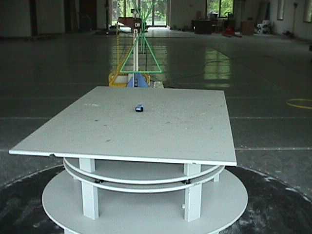
ADVANCED BUSINESS SCIENCES, INC. Application For Certification of the ABS Cuff Transmitter (FCC ID: OAM 1023018) June 28, 1999 All services undertaken are subject to the following general policy: Reports are submitted for exclusive use of the client to whom they are addressed. Their significance is subject to the adequacy and representative character of the samples and to the comprehensiveness of the tests, examinations or surveys made. No quotations from reports or use of Intertek Testing Services name is permitted except as expressly authorized by Intertek Testing Services in writing. The report must not be used by the client to claim product endorsement by NVLAP or any agency of the U.S. Government. The NVLAP logo is applicable for testing to I EC/CISPR 22:1993 and FCC-47 CFR part 15 only. A TABLE OF CONTENTS 1.0General Description............................................................................................1 1.1Related Submittal(s) Grants ..........................................................................1 1.2Product Description ...................................................................................1 1.3Test Methodology .....................................................................................1 1.4Test Facility ............................................................................................1 2.0System Test Configuration...................................................................................2 2.1Justification .............................................................................................2 2.2EUT Exercising Software ............................................................................2 2.3Special Accessories....................................................................................2 2.4Equipment Modification ..............................................................................2 2.5Support Equipment List and Description ..........................................................2 2.6Test Configuration Block Diagram .................................................................2 3.0Emission Results................................................................................................3 3.1Field Strength Calculation............................................................................3 3.2Radiated Emission Data ..............................................................................4 3.3Test Equipment ........................................................................................5 EXHIBIT I Emissions Test Data.......................................................................................................6 A FCC ID: OAM 1023018 Report No:J99011549 - May,1999 Page 1 of 12 1.0 GENERAL DESCRIPTION 1.1 Related Submittals Grants This is single application of the Cuff transmitter for Certification under Part 15.231(e). There are no other simultaneous applications . 1.2 Product Description The wireless cuff includes five components, a battery assembly (hub), “O” ring, transmitter assembly, a bracket and four screws. Battery Assembly-Provides a nominal 6VDC source to power the transmitter when assembled. The transmitter will cease operation at around 3.9VDC. “O” Ring – Seals the transmitter compartment when assembled making it waterproof. Transmitter assembly – Encapsulated transmitter with battery contacts for power. Periodically sends a message to the receiver which resident in the PTU. 1.3Test Methodology Radiated emission measurements were performed according to the procedures in ANSI C63.4 (1992). All measurements were performed in Open Area Test Sites. Preliminary scans were performed in the Open Area Test Sites only to determine worst case modes. For each scan, the procedure for maximizing emissions in Appendices D and E were followed. All Radiated tests were performed at an antenna to EUT distance of 3 meters, unless stated otherwise in the "Justification Section" of this Application. 1.4Test Facility The test site facility used to collect the radiated and conducted measurement data is located at 7435 4th Street North, Oakdale, Minnesota. This test facility has been fully described in a report dated on September 1996 submitted to your office. Please reference the site filing number: 31040/SIT 1300F2, dated December 26, 1996. A FCC ID: OAM 1023018 Report No:J99011549 - May,1999 Page 2 of 12 2.0SYSTEM TEST CONFIGURATION 2.1Justification The EUT was powered from 6VDC Battery assembly. The EUT was set up as tabletop equipment. 2.2 EUT Exercising Software The ABS Cuff transmitter was tested in the continuous transmission mode. 2.3Special Accessories There are no special accessories necessary for compliance of these products. 2.4 Equipment Modification No modifications were installed during the testing. 2.5Support Equipment List and Description N/A 2.6Test Configuration Block Diagram (see Exhibit I) A FCC ID: OAM 1023018 Report No:J99011549 - May,1999 Page 3 of 12 3.0EMISSION RESULTS Data is included of the worst case configuration (the configuration which resulted in the highest emission levels). A sample calculation, configuration photographs, data tables and graphical representations of the emissions are included. 3.1Field Strength Calculation The field strength is calculated by adding the Peak reading on the EMI Receiver to the factors associated with preamplifiers (if any), antennas and cables. A sample calculation is included below. FS = RA + AF + CF - AV Where FS = Field Strength in dB V/m RA = Receiver Amplitude (including preamplifier) in dB V CF = Cable Attenuation Factor in dB AF = Antenna Factor in dB AV = Average Factor Assume a receiver reading of 47 dB V is obtained. The antenna factor of 19.5 dB and cable factor of 3.5 dB is added. The net field strength for comparison to the appropriate emission limit is 67 dB V/m. The average factor of 20dB is subtracted from the readings. A FCC ID: OAM 1023018 Report No:J99011549 - May,1999 Page 4 of 1…
Text truncated - open the document above for the full version.
Test Report
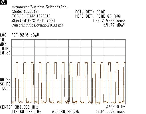
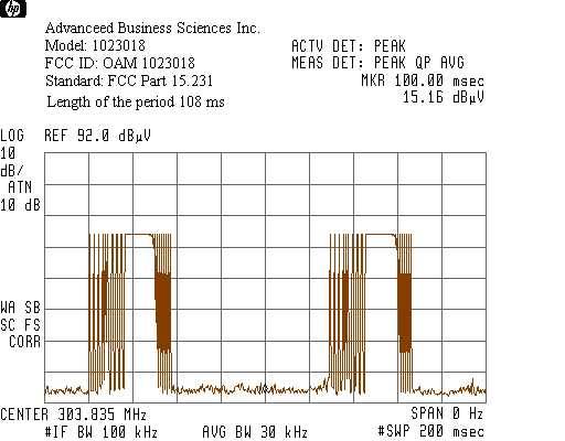
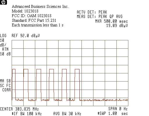
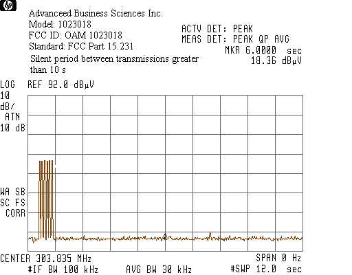
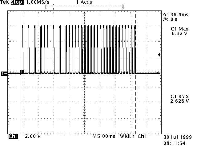
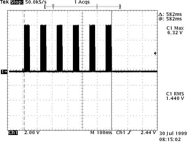
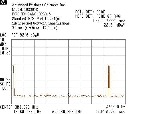
Duty cycle factor calculations The pulse train is less than 100 ms including blank intervals. The duty cycle calculated by averaging the sum of the pulse widths over one complete pulse train. The sum of the pulse widths is 0.32ms x 30 pulses in the train = 9.6 ms The length of the period is 108 ms The duty cycle is 9.6 ms/108 ms = 0.089 The Peak-Average correction factor derived from the duty cycle 20lg(0.089)=-21dB The maximum Peak-Average correction factor is 20dB Please see the attached graphs for the pulse train measurements.
Contact Information
Applicant
Bill Johnson(President)
Technical Contact
Advanced Business Sciences Inc.Walt Carlson
[email protected](402)498-2734
3345 North 107th Street · Omaha, Nebraska · United States
Test Firm
Intertek Testing ServicesUri Spector
Technical Specifications
| # | Rule Parts | Frequency Range | Power Output |
|---|---|---|---|
| 1 | 15.231(e) | 303.825 MHz - 303.825 MHz | - |
Other Applications from Corrisoft
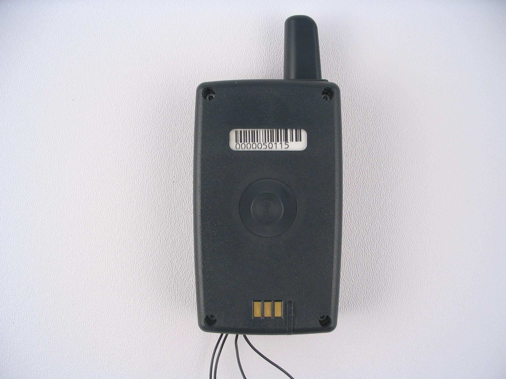
OAM5000
Sep 16, 2007System 5000 PTU
Equipment Class
PCT - PCS Licensed Transmitter worn on body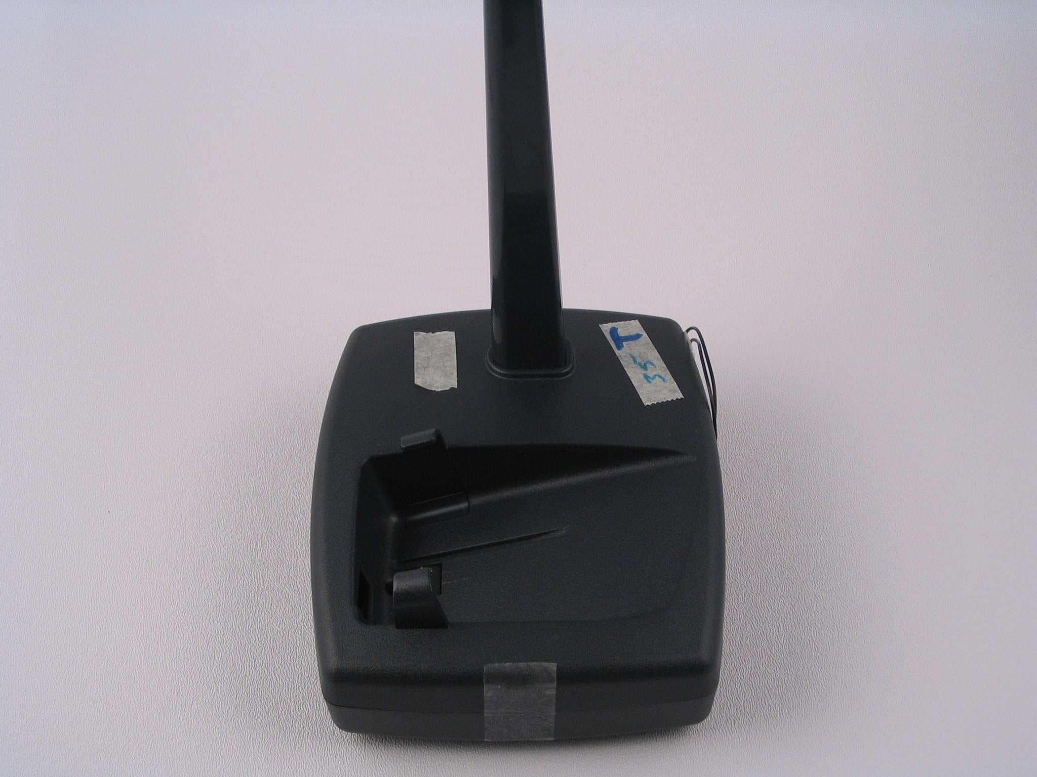
OAM5000BASE
Sep 13, 2007System 5000 Base
Equipment Class
DSC - Part 15 Security/Remote Control Transmitter
OAM2250
Mar 14, 2004Personal Tracking Device
Equipment Class
PCT - PCS Licensed Transmitter worn on body
OAM2100-433
May 20, 2003Personal Tracking Device
Equipment Class
DXT - Part 15 Low Power Transceiver, Rx Verified
OAM2100NC
Apr 29, 2002Personal Tracking Unit
Equipment Class
DXT - Part 15 Low Power Transceiver, Rx Verified