OAM2250Personal Tracking Device
Corrisoft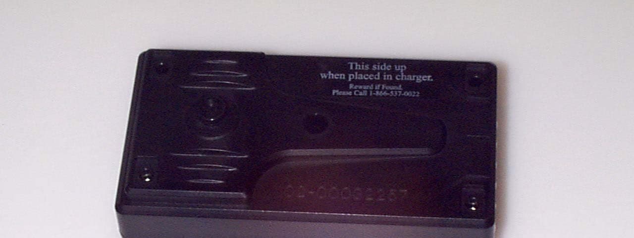
Click to zoom
Application Details
- Equipment Class
- PCT - PCS Licensed Transmitter worn on body
- Date of Grant
- Mar 14, 2004
- Application Purpose
- Original Equipment
- Date of Application
- Mar 14, 2004
- Equipment Note
- Personal Tracking Device
- Frequency Range
- 824.70000000 - 848.31000000
- Company
- Corrisoft
- Country
- United States
Documents & Files
Document Text
Text extracted from the exhibit documents filed with the FCC. Open a document above to read the original.
Users Manual
Users Manual Model 2250 Revision 1 ISECUREtrac Corporation iiSECUREtrac 2250 User’s Manual Rev 1.0 Confidential Page 1 10/1/2003 Introduction This manual covers the installation and removal of the iSECUREtrac Corp 2100NC personal tracking system. Equipment List · iTracker 2250 unit · iSECUREtrac 1025004 charging base · Floor based power module with AC power cord · Telephone cord · iSECUREtrac Bracelet Transmitter (see user manual for bracelet transmitter or installation) Installation Tools · None System Status Indicators · An LED is provided on the Charging base. It will be lit when the charging base is plugged into the power line. It will also be green when the unit is in the charger and is fully charged. The led will be red when the PTU is charging. Connecting a Offender at the Agent's location · The agent enters configuration information into the server software. · The agent forces the unit to call. · The agent confirms configuration has been uploaded to the unit. · The offender comes to the agent’s office. · Wireless bracelet transmitter is attached to the ankle of the offender. · The agent activates the PTU. · The agent gives the offender the PTU and Charging Station. · The offender takes the PTU and Charging Station home. · The offender places the PTU in the Charging Station. · The offender connects the Charging Station to POTS and AC receptacles. Connecting an Offender at Offender’s location · The agent enters configuration information into the server software. · The agent brings equipment to offender’s home location. · The agent connects the Charging Station to POTS and AC. · The agent places the PTU in the charging base. · Wireless transmitter is attached to the ankle of the offender. · The agent confirms proper initialization via beep sequence. · PTU is active when beep sequence confirmed. ISECUREtrac Corporation iiSECUREtrac 2250 User’s Manual Rev 1.0 Confidential Page 2 10/1/2003 Removal of an Offender at Agent's Location · The agent enters removal information into the server software. · PTU will deactivate on next call. · The agent notifies offender of removal. · The offender removes the Charging Station power. · The offender removes the POTS connector. · The offender comes the agent’s office bringing the PTU and Charging Station. · Wireless transmitter is removed from the ankle of the offender. Removal of an Offender at their location · The agent enters removal information into the server software. · PTU will deactivate on next call. · The agent goes to offender’s home location. · Wireless transmitter is removed from the ankle of the offender. · The agent removes the POTS connector. · The agent removes the Charging Station Power. · The agent leaves the offender’s home. Location of the Charging base at offenders location · The unit should be set on a level a table at least 30 inches off the floor · The table should not be close to a source of water or a location where it will be easily knocked to the floor. · The unit should be several feet away from electrical kitchen appliances and televisions sets. · The best location is the center of the dwelling, to provide the same distance between the bracelet receiver and when its transmitter is at the extreme areas of the dwelling, i.e. the center of the inclusion zone. Wearing the PTU · The PTU should be worn at all times on a belt around the offender waist (use the provided belt clip) to prevent damage. · Do Not wear the unit such that it is closer 1 ft to the head of the Offender · Do Not submerge in water. · Do Not drop. · When in a car place the unit in provided window clip out of direct summertime sun light, with the belt clip down. Note: This equipment has been tested and found to comply with the limits for a class B digital device and Specific Absorption Rate, pursuant to 47FCR part 15 of the FCC rules. These limits are designed to provide reasonable protection against harmful interference and /or exposure in a residential installation. ISECUREtrac Corporation iiSECUREtrac 2250 User’s Manual Rev 1.0 Confidential Page 3 10/1/2003 FCC Requirements 1. The Federal Communications Commission (FCC) has established Rules Which permit this device to be directly connected to the telephone network. Standardized jacks are used for these connections. This equipment should not be used on party lines or coin phones. 2. If this device is malfunctioning and is causing harm to the telephone network... this device should be disconnected until the source of the problem can be determined and until repair has been made. If this is not done, the telephone company may temporarily disconnect service. 3. The telephone company may make changes in its technical operations and procedures. If such changes affect the compatibility or use of this device, the telephone company is required to give adequate notice of the changes. You will be advised of your right to file a complaint with the FCC. 4. If the telephone company requests information on what equipment is connected to their lines, inform them of: a. The FCC Registration Number. 0006-3646-40 b. The FCC ID number is OAM2250 Caution to the user Changes or modifications not expressly approved by the party responsible for compliance could void the user's authority to operate the equipment Service Requirements In the event of equipment malfunction, all repairs should be performed by our Company or an authorized agent. It is the responsibility of users requiring service to report the need for service to our Company or to one of our authorized agents, Service can be obtained at iSECUREtrac Corp. 5022 S. 114 th Street Suite 103 Omaha, NE 68137
Cover Letter(s)
From: Bryan Taylor ES-Lex Sent: Friday, February 20, 2004 11:11 AM To: Roland Gubisch ES-Box Cc: Thomas Eng ES-Mpk; David Schramm ES-Atl; Danielle Fontaine ES-Box Subject: RE: TCB certification of iSECUREtrac FCC ID: OMA2250 All, I have attached some updated documents addressing the issues below. I have also made comments below each item detailing the changes implemented. In speaking with the client, I found that they are not manufacturing the external antenna model. I removed the references to the external antenna model in the documentation. Regards, Bryan -----Original Message----- From: Roland Gubisch ES-Box Sent: Friday, February 13, 2004 6:55 PM To: Bryan Taylor ES-Lex Cc: Thomas Eng ES-Mpk; David Schramm ES-Atl; Danielle Fontaine ES-Box Subject: TCB certification of iSECUREtrac FCC ID: OMA2250 Bryan, Review of this application is complete and the following points are noted; ADMINISTRATIVE 1) Request for confidentiality asks to cover internal photos, in addition to customary exhibits. Use of device justifies this request, but the letter should reference the relevant 47 CFR Rules (0.459). Please refer to the attached pro forma for an example. The client sent a new letter which is attached. 2) Modulation designator G9W used for CDMA in Form 731 and EMC report does not agree with FCC convention of F9W; please amend. Fixed in both places. 3) EMC test report describes EUT as "wireless desk phone." Please amend to agree with user manual. Changed to match what appears on the users manual. 4) Please provide separate SAR setup, external and internal photo exhibits; they must be uploaded separately to FCC database. Also, both side of each PCB must be shown ; an additional photo of one side of the PCB is needed. There is now a SAR photos document, internal photo exhibit, and external photo exhibit. 5) 2.1033(c)(8) DC voltage and current into final RF stage cannot be found; please indicate where it is found, or provide. The CDMA module manufacturer (AnyDATA) has stated that this can be found in their users manual. I had problems getting the manual from the FCC website although it is not a confidential document. The model number of the CDMA module is DT2000DUAL. The one in the device does not have an FCCID on it. 6) 2.1033(c)(9) Tune up information cannot be found; please indicate where it is found, or provide. It is attached. 7) PCS frequency range reported on Form 731 should represent center frequencies of lowest and highest bands, not block edges; please amend Fixed EMC REPORT 1) Conducted output is reported as 0.3W, yet EIRP is measured as only 16.7 mW. Please re-do and re-check reported ERP as well. Note that ERP and EIRP are usually reported on Form 731, not conducted power. Repeated ERP/EIRP measurements on internal antenna. New data is in the report and on 731 form. 2) Spurious radiated emissions found within 20 dB of the equivalent -13 dBm limit must be measured by TIA-603 substitution method, as dBm. Please perform substitution measurements for the internal and external antenna configurations, AMPS and PCS bands, where such emissions are plotted. This is in the report on page 26. SAR REPORT 1) Table on p.3 reports maximum 1g SAR of 0.124 W/kg, Table on p. 16 reports maximum 1g SAR of 0.200 W/kg. Please explain difference. Fixed the table on page 3. It was reflecting the SAR value un-extrapolated for drift. 2) Is the belt clip metallic? What spacing from the phantom does it provide? Please add these details to the test report. Added info on the belt clip to the table on page 5. 3) Are there any battery options? Please describe. Added info on the one battery option to the table on page 5. 4) What does the external antenna look like? Please provide a photo. There is no external antenna model being manufactured. Removed references to the external antenna. 5) Was a duty cycle factored mathematically into the calculation of SAR? Yes. Added a statement on this just above the data table. 6) No correlation of EIRP, ERP or conducted power is indicated in SAR report, corresponding to EMC report values; see SAR report clause 3.4.2. Please provide data showing that SAR was measured at same output power as EMC data, within 5% tolerance or as justified owing to unusual duty cycle of EUT. Added the conducted power to the data table. 7) Test parameters for SAR plots are unreadable, owing to low resolution. Please re-submit plots with legible captions. If exhibit becomes too large (> 4 MB), consider splitting calibration data into a separate exhibit. Increased the quality of the pdf file. In doing this I had to remove the appendix to keep the file size down. The appendix is now a separate document. 8) The plot on p.20 truncates a local maximum value; please justify, or re-scan to show complete profile. Removed the plot on pate 20. It was for the external antenna which is not being manufactured. Certification can proceed when these issues are addressed. Thank you. Regards, Roland Gubisch << File: Confidentiality pro forma.doc >>
External Photos
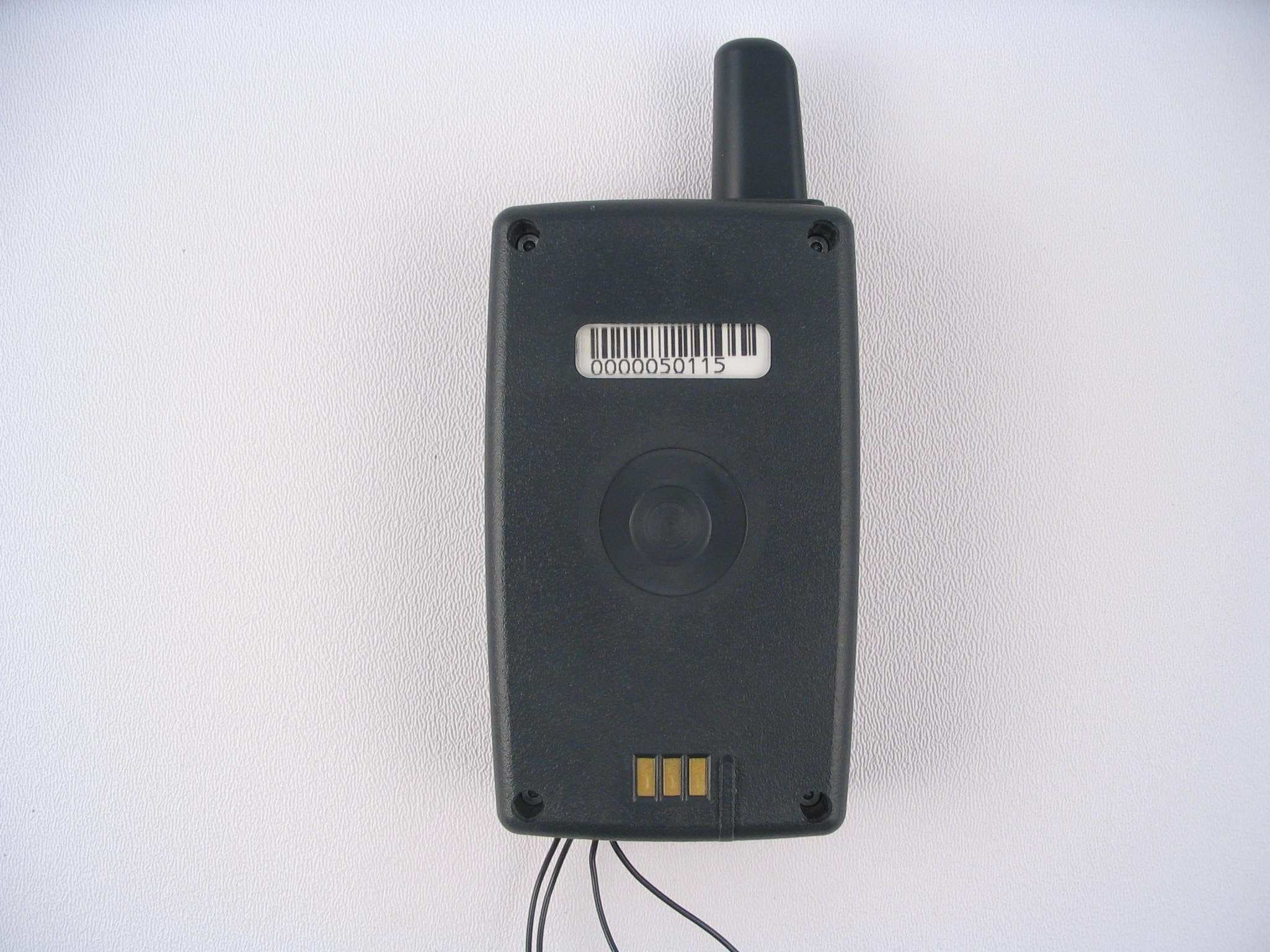
EUT With Belt Clip Installed EUT With Belt Clip Removed
ID Label/Location Info
5022 South 114 th Street Omaha, NE 68137 [p]866.537.0022 [f]402.537.9847 www.isecuretrac.com Date: 9/29/2003 Intertek -ETL SEMKO 731 Enterprise Drive Lexington, KY 40510 To Whom It May Concern: In accordance with 47 CFR, iSECUREtrac Corp. will label the equipment listed below in the manner illustrated on the following page. Equipment: iTracker™ Model 2250 Personal Tracking Device (PTU) iTracker™ Charger Mr. David Sempek Chief Technical Officer (402) 537 - 9834 2/28/2002 5022 South 114 th Street Omaha, NE 68137 [p]866.537.0022 [f]402.537.9847 www.isecuretrac.com 2 iTracker™ Model 2250 PTU Size_1.5”_ in. x _ 1_ in. Model 2250 Series PTU FCC:OAM2250 This device complies with part 15 of the FCC Rules. Operation is subject to the following two conditions: (1) this device may not cause harmful interference, and (2) this device must accept any interference received, including interference that may cause undesired operation The Label will be white with black letters. The text font will be white Arial 6 point. iTracker™ Charger Label Placement Size_1 1/4”_ in. x _3 1/2_ in. The Label will be colored as shown. The ID text font will be Arial 8 point bold. Initial____ Location of FCC identification label. This device complies with part 15 of the FCC rules. Operation is subject to the following two conditions: (1) This device may not cause harmful interference, and (2) This device must accept any interference received, including interference that may cause undesired operation. FCC ID # OAM2250
Operational Description
DC power into RF; 2.1033(c)(8) The internal RF transmitter module operates with these DC ratings: DC voltage: 3.4 - 4.2 V standby current: 2 mA idle current: 110 mA busy current: 900 mA
Parts List/Tune Up Info
Tune up procedure To set up transmit power before shipping, AnyDATA uses a manufacturing process which is called “Calibration of Rx and Tx power over the dynamic range, temperature and frequency”. CDMA technical standard requires AnyDATA’s CDMA module to transmit more than +23dBm output power when it is required to transmit its maximum power. Therefore, AnyDATA sets the maximum power of the module to +24dBm (+/-) 1dB. By adjusting Tx AGC Amplifier built in the CDMA module, transmit power can be limited to +24dBm (+/-) 1dB. Transmit power calibration consists of transmit linearizer calibration, and power compensation calibration over the temperature and frequency. During the transmit linearizer calibration, the module searches for 16 AGC adjust values for the 16 power levels within the dynamic range including the maximum output power and saves these AGC adjust values in the memory device in the module. These searched AGC adjust values (TX_LIN_MASTER) set the maximum power of the module. To prevent the variation in maximum power over the frequency, the transmit circuit is calibrated over the frequency and compensation values (TX_LIM_VS_FREQ) are found. These values are also used to limit the maximum output power to +24dBm (+/-)1dB. Also to prevent the variation in maximum power over the temperature, the transmit circuit is calibrated over the temperature and compensation values (TX_LIM_VS_TEMP) are found. These are also used to limit the maximum output power to +24dBm (+/-)1dB when there is a variation in temperature..
RF Exposure Info
This report may be reproduced only with the written permission of Intertek and if reproduced must be reproduced in its entirety. This report must not be used to claim product endorsement by NVLAP or any agency of the U.S. Government. The results contained in this report were derived from measurements performed on the identified test samples. Any implied performance of other samples based on this report is dependent on the representative adequacy of the samples tested. SAR TEST REPORT Report Number: 3047435-002 Project Number: 3048625 October 20, 2003 Evaluation of the 2100NC personal tracking system Model Number: 2250 FCC ID: OAM2250 FCC Part 2.1093 For ISECUREtrac Corp. Test Performed by: Test Authorized by: Intertek 731 Enterprise Drive Lexington, KY 40510 ISECUREtrac Corp. 5022 South 114th Street Omaha, NE 68137 Prepared By:_______________________________Date:____1/23/2004________ Bryan C. Taylor, Team Leader Approved By:_______________________________Date:____1/23/2004_______ Reviewing Engineer, Title Intertek 731 Enterprise Drive, Lexington, KY 40510 Telephone: 859-226-1000 Fax: 859-226-1040 Web: www.etlsemko.com 731 Enterprise Drive, Lexington KY 40510 Evaluation For:ISECUREtrac Corp. FCC ID: OAM2250 Model No: 2250 File: 3048625 Page 2 of 18 FCC Part 2.1093 TABLE OF CONTENTS 1 INTRODUCTION 3 2 JOB DESCRIPTION 4 2.1 CLIENT INFORMATION 4 2.2 TEST PLAN REFERENCE: 4 2.3 EQUIPMENT UNDER TEST (EUT) 5 2.3.1 System Support Equipment 6 2.3.2 Table 2-1: System Support Equipment 6 2.3.3 Cables associated with EUT 6 2.3.4 System Block Diagram 6 2.3.5 Justification 7 2.3.6 Mode(s) of operation 7 2.4 MODIFICATIONS REQUIRED FOR COMPLIANCE 7 2.5 RELATED SUBMITTAL(S) GRANTS 7 2.6 TEST SITE DESCRIPTION 8 2.7 MEASUREMENT UNCERTAINTY 9 2.8 MEASUREMENT TRACTABILITY 10 3 SPECIFIC ABSORBTION RATE 11 3.1 TEST LIMITS 11 3.2 TEST EQUIPMENT 12 3.3 TISSUE SIMULATING LIQUID DESCRIPTION AND VALIDATION 13 3.4 DIPOLE SYSTEM VALIDATION 14 3.4.1 Test Procedure 15 3.4.2 Conducted Output Power: 15 3.4.3 Test Positions: 15 3.4.4 Reference Power Measurement: 15 3.4.5 Coarse Scan: 15 3.4.6 Zoom Scan: 15 3.4.7 Data Extrapolation: 15 3.4.8 Reference Power Measurement: 16 3.4.9 RF Ambient Activity: 16 3.5 TEST RESULTS 16 731 Enterprise Drive, Lexington KY 40510 Evaluation For:ISECUREtrac Corp. FCC ID: OAM2250 Model No: 2250 File: 3048625 Page 3 of 18 FCC Part 2.1093 1 INTRODUCTION The 2250 was evaluated for SAR in accordance with the requirements for RF Exposure compliance testing defined in FCC OET Bulletin 65, Supplement C (Edition 01-01). Testing was performed at the Intertek Testing Services facility in Lexington, Kentucky. For the evaluation, the dosimetric assessment system DASY3 was used. The phantom employed was the "SAM Twin Phantom". The total uncertainty for the evaluation of the spatial peak SAR values averaged over a cube of 1g tissue mass had been assessed for this system to be ±27.4%. The device was tested at the maximum output power. This was accomplished using a Rhode & Schwarz CMU-200 base station simulator to force the device into a “call”. Once in a “call” the base station simulator was configured to send the EUT an “all up bits” signal which forced the device to transmit at maximum power output. The maximum spatial peak SAR value for the sample device averaged over 1g was found to be: Phantom Position Worst Case Extrapolated SAR 1g mW/g 1 Flat Section Belt Clip Against Phantom; Cell Band Channel 384; Internal Antenna 0.200 Based on the worst case data presented above, the sample tested was found to be in compliance with the requirements defined in OET Bulletin 65, Supplement C (Edition 01-01). 1 Data has been corrected for duty cycle. 731 Enterprise Drive, Lexington KY 40510 Evaluation For:ISECUREtrac Corp. FCC ID: OAM2250 Model No: 2250 File: 3048625 Page 4 of 18 FCC Part 2.1093 2 JOB DESCRIPTION 2.1 Client information The 2100NC personal tracking system has been tested at the request of Company: ISECUREtrac Corp. 5022 South 114th Street Omaha, NE 68137 Name of contact: Jef Higgason Telephone: (402)-537-5663 Fax: (402)-537-9847 2.2 Test plan reference: Tests were performed to the following standards: • FCC Part 2.1093 731 Enterprise Drive, Lexington KY 40510 Evaluation For:ISECUREtrac Corp. FCC ID: OAM2250 Model No: 2250 File: 3048625 Page 5 of 18 FCC Part 2.1093 2.3 Equipment Under Test (EUT) The 2250 was a Mobile Wireless Terminal used for scanning credit cards. The unit operated in the CDMA 800 and 1900 band using an internal antenna. The following is a detailed description of the EUT. Product 2100NC personal tracking system EUT Model Number 2250 EUT Serial Number Not Marked Not Labeled Whether quantity (>1) production is planned Quantity production is planned. Cellular Phone standards CDMA 800 and 1900 Type(s) of Emission 1M29G9W RF Output Power 23.86 dBm – CDMA 800 25.76 dBm – CDMA1900 Frequency Range 824.7 – 848.31 MHz 1850 – 1910 MHz CDMA800 CDMA1900 Antenna & Gain Integrated, non-retractable (internal) Detachable Antenna None Belt Clip Detachable plastic belt clip with metal spring. Provides 2.5 cm of spacing between the body and the chassis of the device. Battery Option 7.2V 22mAh Li-ion Battery 2 External input [ ] Audio [ X] Digital Data EUT receive date: 9/24/2003 EUT receive condition: The EUT was received in good condition with no apparent damage. Test start date: 9/24/2003 Test completion date: 10/8/2003 The test results in this report pertain only to the item tested. 2 No other battery options are offered. 731 Enterprise Drive, Lexington KY 40510 Evaluation For:ISECUREtrac Corp. FCC ID: OAM2250 Model No: 2250 File: 3048625 Page 6 of 18 FCC Part 2.1093 2.3.1 System Support Equipment Table 2-1 contains the details of the support equipment associated with the Equipment Under Test during the testing. 2.3.2 Table 2-1: System Support Equipment Description Manufacturer Model Number Serial Number FCC ID number Charging Base ISECUREtrac Corp 2250 007095-0514 Not Labeled Charging Base ISECUREtra…
Text truncated - open the document above for the full version.
RF Exposure Info
SAR Testing Against the Flat Phantom
Test Report
This report may be reproduced only with the written permission of Intertek and if reproduced must be reproduced in its entirety. This report must not be used to claim product endorsement by NVLAP or any agency of the U.S. Government. The results contained in this report were derived from measurements performed on the identified test samples. Any implied performance of other samples based on this report is dependent on the representative adequacy of the samples tested. TEST REPORT Report Number: 3048625-002 Project Number: 3048625 October 20, 2003 Evaluation of the 2100NC personal tracking system Model Number: 2250 FCC ID: OAM2250 FCC Part 2 FCC Part 15 FCC Part 24 Subpart E For ISECUREtrac Corp. Test Performed by: Test Authorized by: Intertek 731 Enterprise Drive Lexington, KY 40510 ISECUREtrac Corp. 5022 South 114th Street Omaha, NE 68137 Prepared By:_______________________________Date:____9/12/2003________ Bryan C. Taylor, Team Leader Approved By:______________________________Date:____Date_________ Reviewing Engineer, Title Intertek 731 Enterprise Drive, Lexington, KY 40510 731 Enterprise Drive, Lexington KY 40510 Evaluation For:ISECUREtrac Corp. FCC ID: OAM2250 Model No: 2250 File: 3048625 Page 2 of 47 FCC Part 2, 15, and 24 Evaluation TABLE OF CONTENTS 1 EXECUTIVE SUMMARY................................................................................................................. 4 2 JOB DESCRIPTION .......................................................................................................................... 5 2.1 CLIENT INFORMATION................................................................................................................. 5 2.2 TEST PLAN REFERENCE: ............................................................................................................... 5 2.3 EQUIPMENT UNDER TEST (EUT) ................................................................................................. 6 2.3.1 System Support Equipment...................................................................................................... 7 2.3.2 Cables associated with EUT ................................................................................................... 7 2.3.3 System Block Diagram ............................................................................................................7 2.3.4 Justification ............................................................................................................................. 8 2.3.5 Mode(s) of operation............................................................................................................... 8 2.4 MODIFICATIONS REQUIRED FOR COMPLIANCE............................................................................ 8 2.5 RELATED SUBMITTAL(S) GRANTS............................................................................................... 8 3 TEST FACILITY................................................................................................................................ 9 4 CONDUCTED RF POWER ............................................................................................................ 10 4.1 TEST PROCEDURE...................................................................................................................... 10 4.2 TEST EQUIPMENT....................................................................................................................... 10 4.3 TEST RESULTS........................................................................................................................... 10 5 RADIATED RF POWER ................................................................................................................. 11 5.1 TEST PROCEDURE...................................................................................................................... 11 5.2 TEST EQUIPMENT....................................................................................................................... 11 5.3 TEST RESULTS........................................................................................................................... 12 6 EMISSION LIMITATIONS, OCCUPIED BANDWIDTH .......................................................... 13 6.1 TEST PROCEDURE...................................................................................................................... 13 6.2 TEST EQUIPMENT....................................................................................................................... 13 6.3 TEST RESULTS........................................................................................................................... 14 7 OUT OF BAND EMISSION AT ANTENNA TERMINALS........................................................ 18 7.1 TEST PROCEDURE...................................................................................................................... 18 7.2 TEST EQUIPMENT....................................................................................................................... 18 7.3 TEST RESULTS........................................................................................................................... 19 8 FIELD STRENGTH OF SPURIOUS RADIATION ..................................................................... 25 8.1 TEST PROCEDURE...................................................................................................................... 25 731 Enterprise Drive, Lexington KY 40510 Evaluation For:ISECUREtrac Corp. FCC ID: OAM2250 Model No: 2250 File: 3048625 Page 3 of 47 FCC Part 2, 15, and 24 Evaluation 8.2 TEST EQUIPMENT....................................................................................................................... 25 8.3 TEST RESULTS........................................................................................................................... 26 9 POWER LINE CONDUCTED EMISSIONS ......................................…
Text truncated - open the document above for the full version.
Contact Information
Applicant
Bill Johnson(President)
Technical Contact
iSECUREtrac CorpDavid Sempek
[email protected]402 537 5667
5022 S 114th Street · Omaha, Nebraska · United States
Non-Technical Contact
iSECUREtrac CorpJef Higgason
[email protected]402 537 5667
Technical Specifications
| # | Rule Parts | Frequency Range | Power Output | Emission | Tolerance |
|---|---|---|---|---|---|
| 2 | 22H | 824.7 MHz - 848.31 MHz | 142.00 mW | 1M29F9W | 2.5 ppm |
Other Applications from Corrisoft
OAM5000
Sep 16, 2007System 5000 PTU
Equipment Class
PCT - PCS Licensed Transmitter worn on body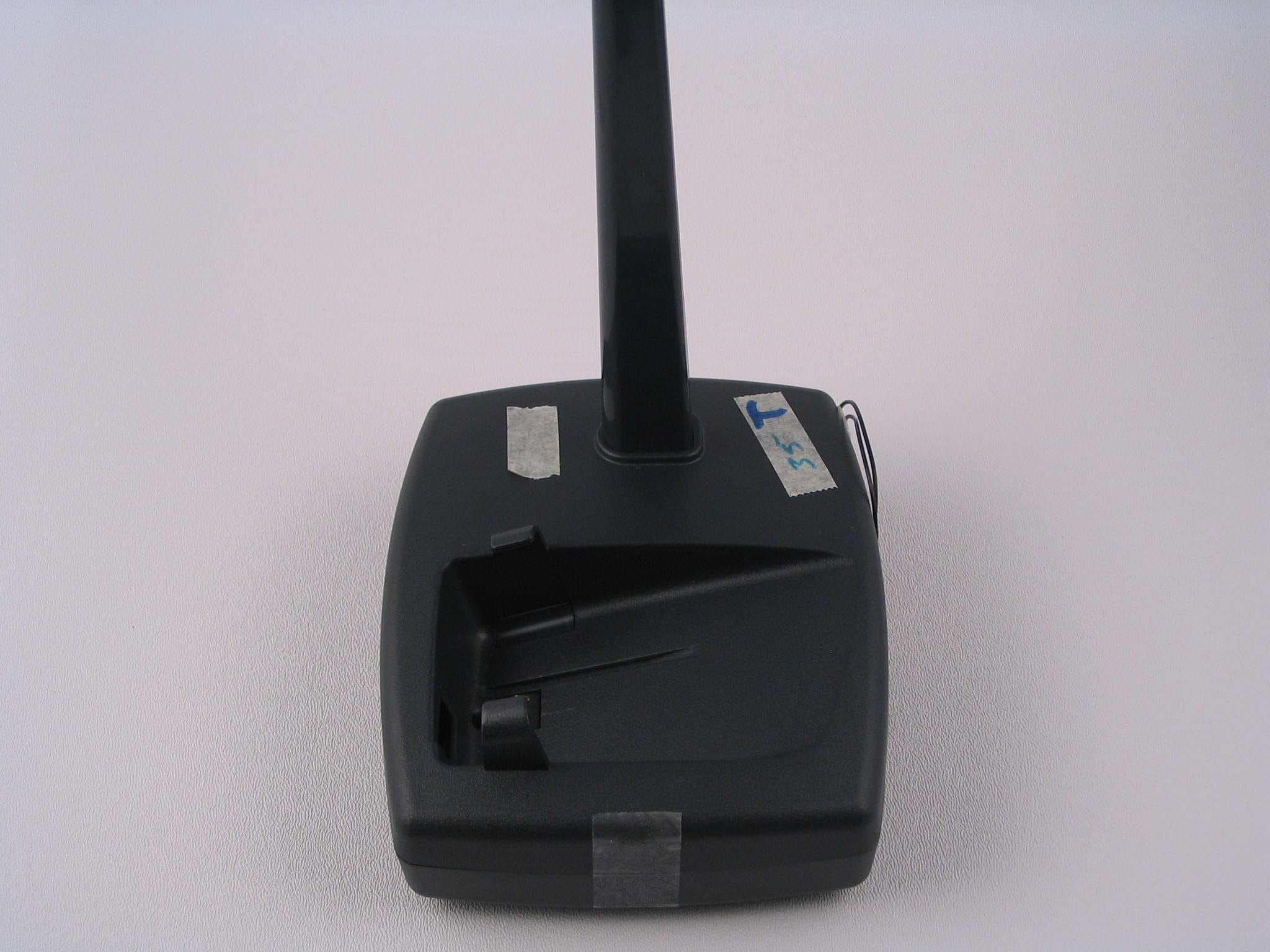
OAM5000BASE
Sep 13, 2007System 5000 Base
Equipment Class
DSC - Part 15 Security/Remote Control Transmitter
OAM2100-433
May 20, 2003Personal Tracking Device
Equipment Class
DXT - Part 15 Low Power Transceiver, Rx Verified
OAM2100NC
Apr 29, 2002Personal Tracking Unit
Equipment Class
DXT - Part 15 Low Power Transceiver, Rx Verified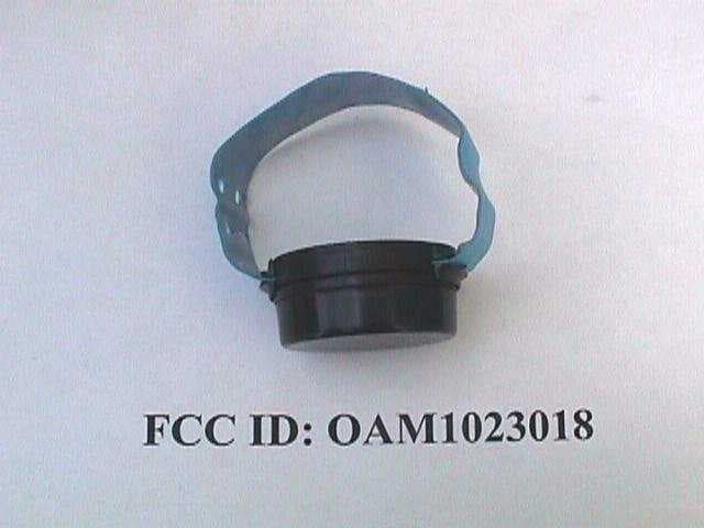
OAM1023018
Sep 06, 1999DSC - Part 15 Security/Remote Control Transmitter
Equipment Class
DSC - Part 15 Security/Remote Control Transmitter