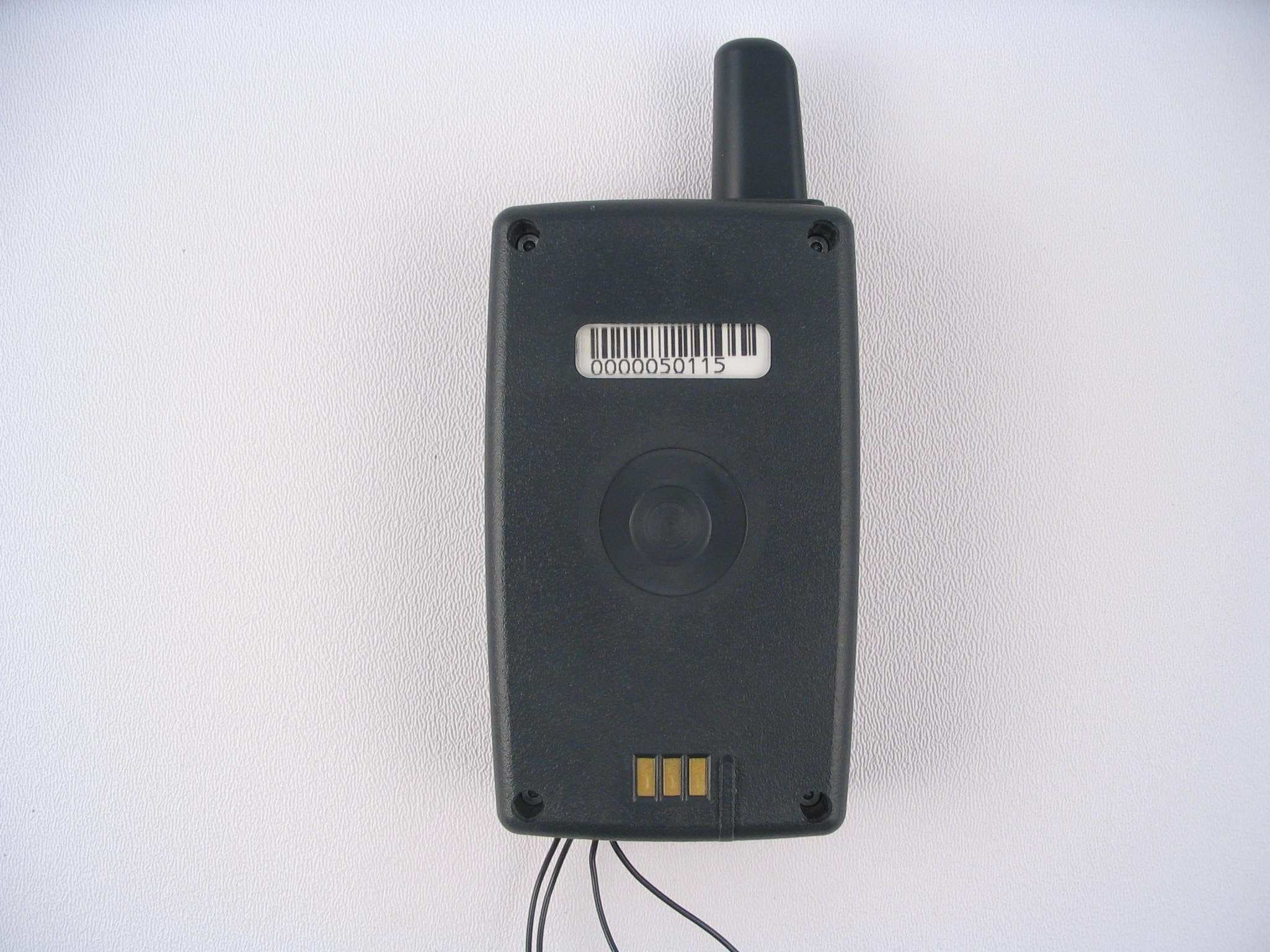
OAM2100-433Personal Tracking Device
Corrisoft
Click to zoom
Application Details
- Equipment Class
- DXT - Part 15 Low Power Transceiver, Rx Verified
- Date of Grant
- May 20, 2003
- Application Purpose
- Original Equipment
- Date of Application
- May 20, 2003
- Equipment Note
- Personal Tracking Device
- Frequency Range
- 433.00000000 - 433.00000000
- Company
- Corrisoft
- Country
- United States
Documents & Files
Document Text
Text extracted from the exhibit documents filed with the FCC. Open a document above to read the original.
Users Manual
Users Manual Model 2130 Revision 1 ISECUREtrac Corporation iiSECUREtrac 2130 User’s Manual Rev 1.0 Confidential Page 1 5/22/2003 Introduction This manual covers the installation and removal of the iSECUREtrac Corp 2100NC personal tracking system. Equipment List · iTracker 2130 unit · iSECUREtrac 1025004 charging base · Floor based power module with AC power cord · Telephone cord · iSECUREtrac Bracelet Transmitter 2100BT (see user manual for bracelet transmitter or installation) Installation Tools · None System Status Indicators · An LED is provided on the Charging base. It will be lit when the charging base is plugged into the power line. It will also be green when the unit is in the charger and is fully charged. The led will be red when the PTU is charging. Connecting a Offender at the Agent's location · The agent enters configuration information into the server software. · The agent forces the unit to call. · The agent confirms configuration has been uploaded to the unit. · The offender comes to the agent’s office. · Wireless bracelet transmitter is attached to the ankle of the offender. · The agent activates the PTU. · The agent gives the offender the PTU and Charging Station. · The offender takes the PTU and Charging Station home. · The offender places the PTU in the Charging Station. · The offender connects the Charging Station to POTS and AC receptacles. Connecting an Offender at Offender’s location · The agent enters configuration information into the server software. · The agent brings equipment to offender’s home location. · The agent connects the Charging Station to POTS and AC. · The agent places the PTU in the charging base. · Wireless transmitter is attached to the ankle of the offender. · The agent confirms proper initialization via beep sequence. · PTU is active when beep sequence confirmed. ISECUREtrac Corporation iiSECUREtrac 2130 User’s Manual Rev 1.0 Confidential Page 2 5/22/2003 Removal of an Offender at Agent's Location · The agent enters removal information into the server software. · PTU will deactivate on next call. · The agent notifies offender of removal. · The offender removes the Charging Station power. · The offender removes the POTS connector. · The offender comes the agent’s office bringing the PTU and Charging Station. · Wireless transmitter is removed from the ankle of the offender. Removal of an Offender at their location · The agent enters removal information into the server software. · PTU will deactivate on next call. · The agent goes to offender’s home location. · Wireless transmitter is removed from the ankle of the offender. · The agent removes the POTS connector. · The agent removes the Charging Station Power. · The agent leaves the offender’s home. Location of the Charging base at offenders location · The unit should be set on a level a table at least 30 inches off the floor · The table should not be close to a source of water or a location where it will be easily knocked to the floor. · The unit should be several feet away from electrical kitchen appliances and televisions sets. · The best location is the center of the dwelling, to provide the same distance between the bracelet receiver and when its transmitter is at the extreme areas of the dwelling, i.e. the center of the inclusion zone. Wearing the PTU · The PTU should be worn at all times on a belt around the offender waist (use the provided belt clip or pouch) to prevent damage. · Do Not wear the unit such that it is closer 1 ft to the head of the Offender · Do Not submerge in water. · Do Not drop. · When in a car place the unit on the seat, out of direct summertime sun light, with the belt clip down. Note: This equipment has been tested and found to comply with the limits for a class B digital device and Specific Absorption Rate, pursuant to 47FCR part 15 of the FCC rules. These limits are designed to provide reasonable protection against harmful interference and /or exposure in a residential installation. ISECUREtrac Corporation iiSECUREtrac 2130 User’s Manual Rev 1.0 Confidential Page 3 5/22/2003 FCC Requirements 1. The Federal Communications Commission (FCC) has established Rules Which permit this device to be directly connected to the telephone network. Standardized jacks are used for these connections. This equipment should not be used on party lines or coin phones. 2. If this device is malfunctioning and is causing harm to the telephone network... this device should be disconnected until the source of the problem can be determined and until repair has been made. If this is not done, the telephone company may temporarily disconnect service. 3. The telephone company may make changes in its technical operations and procedures. If such changes affect the compatibility or use of this device, the telephone company is required to give adequate notice of the changes. You will be advised of your right to file a complaint with the FCC. 4. If the telephone company requests information on what equipment is connected to their lines, inform them of: a. The telephone number to which this unit is connected. End user phone number b. The ringer equivalence number. 0.3 c. The USOC jack required. RJ 11C d. The FCC Registration Number. XXXXXXXXXXXX e. The FCC ID number is OAM2100_433 items (b), (d) and (e) are indicated on the label. The Ringer Equivalence Number (REN) is used to determine how many devices can be connected to your telephone line. In most areas, the sum of the REN's of all devices on any one line should not exceed five (5.0). If too many devices are attached, they may not ring properly. Caution to the user Changes or modifications not expressly approved by the party responsible for compliance could void the user's authority to operate the equipment Service Requirements In the event of equipment malfunction, all repairs should be performed by our Company or an authorized agent. It is the responsibility of users requiring service to report the need for service to our Company or to one of ou…
Text truncated - open the document above for the full version.
ID Label/Location Info
5022 S 144 th Street #103 Omaha, NE 68137 iTracker™ Model 2130 PTU Size_1.5”_ in. x _ 1_ in. The Label will be clear. The text font will be white Arial 6 point. iTracker™ Charger Label Placement Size_1 1/4”_ in. x _3 1/2_ in. The Label will be colored as shown. The ID text font will be Arial 8 point bold. Initial____ Location of FCC identification label. This device complies with part 15 of the FCC rules. Operation is subject to the following two conditions: (1) This device may not cause harmful interference, and (2) This device must accept any interference received, including interference that may cause undesired operation. FCC ID # OAM 2100_433 This device is certified for operation under part 68. FCC ID # AU7-USA-46014-MD-E
Test Report
R031003-01 FCC ID: OAM2100-433 NCEE NEBRASKA CENTER FOR EXCELLENCE IN ELECTRONICS 4740 Discovery Drive Lincoln, NE 68521 402-472-5880 Test Report Company: iSECUREtrac Corp 5022 S 114th Street Omaha, NE, USA 68138 Contact: Jef Higgason Product: 2130 Base Station FCC ID: OAM2100-433 Test Report No: R031003-01 APPROVED BY: Steve Cass _________________________ General Manager Doug Kramer _________________________ Test Engineer DATE: 1 May 2003 Total Pages: 17 The Nebraska Center for Excellence in Electronics (NCEE) authorizes the above named company to reproduce this report provided it is reproduced in its entirety for use by the company’s employees only. Any use that a third party makes of this report, or any reliance on or decisions made based on it, are the responsibility of such third parties. NCEE accepts no responsibility for damages, if any, suffered by any third party as a result of decisions made or actions based on this report. This report applies only to the items tested. NCEE is a FCC registered lab. Registration #100875 NCEE R031003-01 FCC ID: OAM2100-433 Page 2 of 17 Table of Contents 1.0 Summary of test results 1.1 Test Results 1.2 Test Methods 1.2.1 Conducted Emissions 1.2.2 Radiated Emissions 2.0 Description 2.1 Equipment under test 2.1.1 Identification 2.1.2 EUT received date 2.1.3 EUT tested dates 2.1.4 Manufacturer 2.1.5 Serial number 2.2 Laboratory description 2.3 Special equipment or setup 3.0 Test equipment used 4.0 Detailed Results 4.1 FCC Part 15.203 unique connector for antenna 4.2 FCC Part 15.207 Conducted Emissions 4.3 FCC Part 15.209 Radiated Emissions 4.4 FCC Part 15.231(e) Radiated Emissions Appendix A – Test setup photos Appendix B – Emissions plots Appendix C – Sample calculation NCEE R031003-01 FCC ID: OAM2100-433 Page 3 of 17 1.0 Summary of test results 1.1 Test Results 1.2 Test Methods 1.2.1 Conducted Emissions Measurements of conducted emissions to the limits set in CFR 47 Part 15.207 were conducted using the methods shown in ANSI/IEEE C63.4, 2001. Several configurations were examined the results presented represent a worst-case scenario. The EUT was placed on a wooden table approximately 80cm high, positioned 40cm from the vertical ground plane and 80cm or more away from any other conductive surface. 1.2.2 Radiated Emissions Compliance to CFR 47 Parts 15.109/209 and 15.231(e) was tested in accordance with the methods of ANSI/IEEE C63.4, 2001. Several configurations were examined the results presented represent a worst-case scenario. The EUT was placed on a wooden table approximately 80cm high and centered on a 4m diameter turntable. The table was rotated to maximize emissions. All measurements were taken at a distance of 3m from the EUT. 2.0 Description 2.1 Equipment under test The iSecuretrac personal tracking unit (PTU) and base station work in conjunction with a cuff (worn by the detainee) and software as part of a home arrest system. A variety of cuff transmitters are available from several different manufacturers (i.e. FCC ID: LSQ-TX500) and are not part of this application for certification. The base station receives a signal, decodes it, re-encodes it and transmits it out for reception by the PTU, which is positioned in the base station. If the PTU is not in the base station, the base station is effectively powered off. The PTU receives information from the cuff and relays it to a remote server via a Part 68 approved modem. The PTU is worn at the waist or stored in the base station when applicable. The transmitter in the base station serves the purpose of providing diversified reception of the cuff signal. In many housing environments, there are signal reflections and blockages that cause dead zones of reception. This is caused by reflected signals mixing with the direct path signal and creating nulls, and sometimes just the fact that metal objects like a refrigerator may block either Test Test SpecificationResults CFR 47, FCC Part 15.203Part 15.203Complies CFR 47, FCC Part 15.207 Part 15.207, Class B Complies CFR 47, FCC Part 15.209 Part 15.209, Class B Complies CFR 47, FCC Part 15.231Part 15.231Complies NCEE R031003-01 FCC ID: OAM2100-433 Page 4 of 17 the horizontal or vertical component of the signal. Depending on the position of the cuff being worn by the individual, the signal can vary from one orientation to the other and anything in-between. By providing a repeater receiver with an external antenna that is vertical, a PTU receiver that is horizontal when docked, and retransmitting with an antenna that is horizontal, signals of both horizontal and vertical polarization have an enhanced chance of reception, thus improving overall reception and minimizing reporting to the customer a false loss of signal conditions. 2.1.1 Identification iSecuretrac iTracker 2130 PTU and charging base 2.1.2 EUT received date: 20 March 2003 2.1.3 EUT tested dates: 20 th and 21 st March 2003 2.1.4 Manufacturer: iSecuretrac Corp, Omaha, NE 2.1.5 Serial number PTU: 05-00006026 Base station: FCCb 2.2 Laboratory description All testing was performed at the NCEE Lincoln facility, which is a FCC registered lab. This site has been fully described in a report submitted to your office, and accepted in a letter dated May 4, 2001. Laboratory environmental conditions varied slightly throughout the tests: Relative humidity of 46 ± 4% Temperature of 21 ± 3° Celsius 2.3 Special equipment or setup The device was modified to enable the transmitter to be active continuously instead of waiting for a signal to repeat. NCEE R031003-01 FCC ID: OAM2100-433 Page 5 of 17 3.0 Test equipment used Serial # Manufacturer Model Description Last cal. 1654 EMCO 3142B Biconilog antenna 03-May-02 6415 EMCO 3115 DRG Horn 17-Sep-02 100037 Rohde & Schwarz ESIB26 EMI Test Receiver 11-Jun-02 082001/003 Rohde & Schwarz TS-PR18 Preamplifier N/A 2575 Rohde & Schwarz ES-K1 Software v1.60 N/A 100023 Rohde & Schwarz ESH3-Z5 Artificial Mains 20-Sep-02 4.0 Detailed Results All measurement results are located in…
Text truncated - open the document above for the full version.
Contact Information
Applicant
Bill Johnson(President)
Technical Contact
ISecuretrac CorpDavid Sempek
[email protected]402-537-5667
5022 South 114th Street · Omaha, Nebraska · United States
Test Firm
Nebraska Center for Excellence in ElectronicsSteve Cass
Technical Specifications
| # | Rule Parts | Frequency Range | Power Output |
|---|---|---|---|
| 1 | 15C | 433 MHz - 433 MHz | - |
Other Applications from Corrisoft
OAM5000
Sep 16, 2007System 5000 PTU
Equipment Class
PCT - PCS Licensed Transmitter worn on body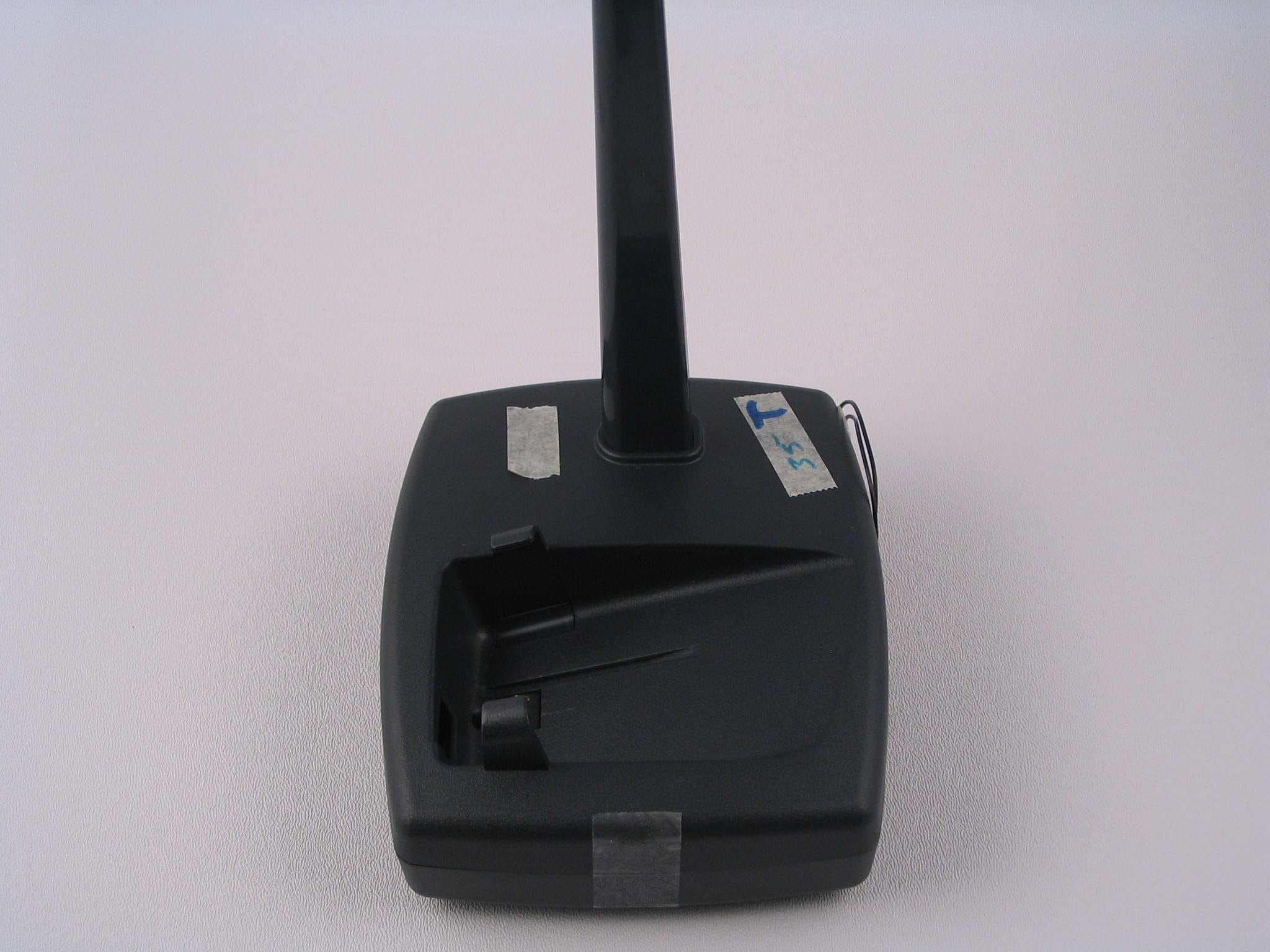
OAM5000BASE
Sep 13, 2007System 5000 Base
Equipment Class
DSC - Part 15 Security/Remote Control Transmitter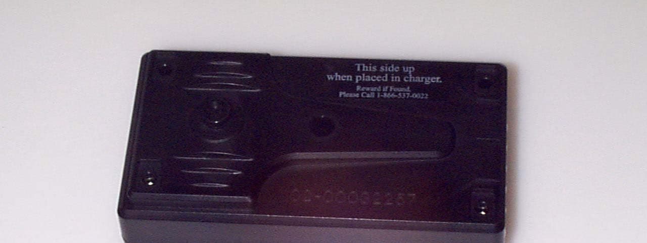
OAM2250
Mar 14, 2004Personal Tracking Device
Equipment Class
PCT - PCS Licensed Transmitter worn on body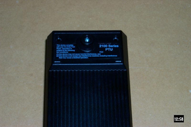
OAM2100NC
Apr 29, 2002Personal Tracking Unit
Equipment Class
DXT - Part 15 Low Power Transceiver, Rx Verified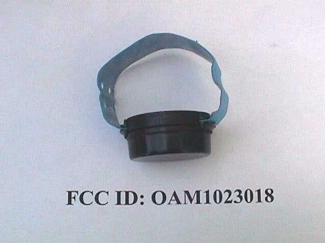
OAM1023018
Sep 06, 1999DSC - Part 15 Security/Remote Control Transmitter
Equipment Class
DSC - Part 15 Security/Remote Control Transmitter