OAM170102Monitoring Device
Corrisoft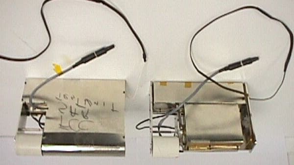
Click to zoom
Application Details
- Equipment Class
- TNT - Licensed Non-Broadcast Transmitter Worn on Body
- Date of Grant
- Jul 21, 1999
- Application Purpose
- Original Equipment
- Date of Application
- Feb 04, 1999
- Equipment Note
- Monitoring Device
- Frequency Range
- 824.00000000 - 849.00000000
- Company
- Corrisoft
- Country
- United States
Documents & Files
Document Text
Text extracted from the exhibit documents filed with the FCC. Open a document above to read the original.
Users Manual
Specification #8810502Original 5/14/98 ABS<Comtrak 1700-1702 Installation & Start-up Procedure 1 Revision, 1/5/99 General Operation: The ABSComtrak 1700 (model 1700) system consists of a Personal Tracking Unit (PTU) and battery charge system. During normal operation the PTU is to be connected to the battery charger for a minimum of seven hours each day. It may than be run for a minimum of seventeen hours before a recharge is required. During this period the client is free to move within the range, from the shoulder pack, that the wireless cuff allows (+/- 20 ft. outdoors and +/- 30 ft. indoors). When moving from one location to the other (i.e. from home to work) the client (with PTU) must remain within +/- 20 ft. of the shoulder pack to avoid a proximity violation. When in a home or other building the client must remain within +/- 30 ft. to avoid a proximity violation. For optimum performance the unit should be in an upright position at all times. When the cuff bracelet is cut/ removed by the client a cuff violation will be communicated to the customer. Charger Installation Procedure: In addition to the Personal Tracking Unit (PTU) each client will be provided with a battery charger, surge suppressor and cable. When set up properly, these three components will allow connection to the client’s home phone line while charging (Reference Figure 1). 1.0 Assure the surge suppressor telephone plug is connected to charger 1.1 Assure ground (green wire) is securely attached to the ground lug on the charger. 1.2 Connect the telephone cable between the surge suppressor jack and telephone jack in the home/office.Connect the battery charger to grounded AC power outlet (110 V, 10 amp minimum). Note: The charger is now ready for charging the batteries in a ABSComtrack 1700. Specification #8810502Original 5/14/98 ABS<Comtrak 1700-1702 Installation & Start-up Procedure 2 Revision, 1/5/99 Figure 1. Battery Charger Assembly Battery Charging Procedure: Note: This process assumes charger installation has been complete. The model 1700 operates for a minimum of 24 full hours . The 24 hour schedule includes a minimum of 7 hours on-line charging plus a minimum of 17 hours independent operation off of two fully charged main batteries. The charging process is as follows: 1. Verify the charger has been set up per “Charger Installation” procedure. 2. Connect the PTU power connector to the battery charger power connector ; “Charge “B” red lamp will light and remain lit until “B” battery pack is fully charged; “A” will continue blinking until “B” is charged. The “Full Chg. B” lamp will then light. “Charge A” red lamp will light and remain lit until “A” battery pack is fully charged. The “Full Chg. A” lamp will light. Both the “A” and “B” battery “Full Chg.” lamps will remain lit as long as the PTU is connected to the charger. 3. The PTU should be left connected to the charger for a minimum three hours (a full 7 hours) after both “Full Chg. Lamps are lit to allow for top-off of both battery pack “A” and “B”. If both lights on the battery charger flash when the PTU is connected the batteries may be in a condition where the charge cannot begin immediately. Leave the charger connected. After a period of time, depending upon conditions, charging will start. Conditions where this could occur include: • when the PTU temperature, due to outdoor exposure is less than approximately 50 degrees. • when the battery voltage has fallen below the minimum voltage but not into a deep discharge condition. • when the time between charge start is greater than 24 hours and the batteries have been allowed to discharge beyond the deep discharge voltage, 9.5 Volts. Caution While charging batteries assure that all four sides and the top of the charger main body are not obstructed. Do not lay blankets, coats or any materials, that would prevent proper ventilation of the charger, over the ventilation ports on the unit. LED Indicators 8 pin DIN connector To RJ11 wall jack Noise/Surge suppressor assembly 3 Prong grounded plug 110 VAC Specification #8810502Original 5/14/98 ABS<Comtrak 1700-1702 Installation & Start-up Procedure 3 Revision, 1/5/99 Wireless Cuff Preparation: The wireless cuff includes five components, a battery assembly (hub), “O” ring, transmitter assembly, a bracelet and four screws. • Battery Assembly - Provides a nominal 6 Volt DC source to power the transmitter when assembled. Life is estimated at 3 months average. The transmitter will cease operation at around 3.9 Volts. • “O” Ring - Seals the transmitter compartment when assembled making it waterproof. • Transmitter Assembly - Encapsulated transmitter with battery contacts for power. Periodically sends a message to the receiver which is resident in the PTU. • Screws, 4 each - #4 Phillips, flat head, stainless steel, sheet metal screws; 3/8” in length. A cuff may be attached to a client once preparation has been completed. Select an appropriate length bracelet for the ankle (table 1), one battery assembly with “O” ring installed, one transmitter assembly and four screws. Sizes 5,6,7 and 8 are stocked by ABS. Other sizes will have to be special ordered at the time of contract. Lead time is two weeks. # of holes Ankle Circumference # of Holes Ankle Circumference 2 6.5” 7 9.0” 3 7.0” 8 9.5” 4 7.5” 9 10.0” 5 8.0” 10 10.5” 6 8.5” 11 11.0” Table 1 Assemble Transmitter and Battery: Align the battery assembly key appropriately with the transmitter assembly slot and lightly engage the hub of the battery assembly to the transmitter cavity. Rotate one assembly carefully until the index mark on one aligns with the index mark on the other. Press the two assemblies together firmly with both hands until little gap can be observed between the two assemblies. Hold them in place with one hand and insert one screw (using a Phillips screwdriver) at a time. Insert the second screw 180 degrees from the first and tighten. The other two screws may be inserted in any order. W…
Text truncated - open the document above for the full version.
Cover Letter(s)
July 21, 1999 Federal Communications Commission Laboratory Division, FCC Equipment Authorization Branch 7435 Oakland Mills Road Columbia, MD 21046 Attention:Mr. Joe Dichoso Reference:Application for Advanced Business Sciences Inc., FCC ID: OAM170102 Ref. # 8819 Dear Mr. Dichoso: The specification number on our client’s confidentiality letter is incorrect, there is no specification number for the theory of operation. The specification #8810502 is for the users manual. A corrected letter of confidentiality is therefore enclosed. Thanks again and regards, Gaspara Lim Enclosure Advanced Business Sciences 3345 N 107 th St. Omaha, NE 68134 pH: 800-218-8057 Fax: 402-498-8812 January 7, 1999 Federal Communications Commission Authorization and Evaluation Division Laboratory Division 7435 Oakland Mills Road Columbia, MD 21046 Dear Sir/Madam: In accordance with the 0.459 of CFR 47 of the FCC Rules, Advanced Business Sciences, Inc., requests confidentiality for the following: • Schematic Diagram • Block Diagram • Theory of operation and technical description (Specification #88101107) These documents contain detailed equipment description and information which considers to be proprietary and can not be released to the public. Sincerely, Donald E. Reiner Director of Manufacturing and Quality Assurance pH: 402-498-2734 Fax: 402-498-8812 A dvanced B usi ness S ci ences, I nc.
External Photos
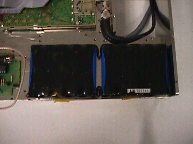
Page 1 of 3 Created on 05/26/99 8:20 AM Last printed 05/26/99 8:47 AM Revision 1.00 Pictures of out 1701 unit.doc The 1701 will always be placed in a cloth bag which has a security seal on it. This is to prevent the parolee from opening the package and tampering with the electronic. Picture 1 shows the unit in the bag and this is this is the standard packaging configuration. Picture 1 The following pictures are of the unit once it is removed from the cloth bag. This condition will only occur when the unit is under repair at and ABS repair facility. The left unit has the outer most metal cover still on and the left unit has it removed. This will give an exploratory view of the unit. Picture 2 Front of unit Cell phone Antenna 303.825MHz receiver antenna GPS receiver antenna Sealed cloth bag. CPU, GPS receiver and interface board 303.825MHz receiver antenna GPS antenna Charger and Telco connector cable Page 2 of 3 Created on 05/26/99 8:20 AM Last printed 05/26/99 8:47 AM Revision 1.00 Pictures of out 1701 unit.doc Pcture 3 Back of unit Picture 4 Bottom of unit 303.825MHz Receiver Main battery Power supply AMPS Cell phone Main battery Power supply Backup battery Page 3 of 3 Created on 05/26/99 8:20 AM Last printed 05/26/99 8:47 AM Revision 1.00 Pictures of out 1701 unit.doc
ID Label/Location Info
March 24, 1999 Federal Communications Commission Equipment Authorization Division 7435 Oakland Mills Road Columbia, MD 21046 Attention: Ms. Jaunice Green Reference: FCC Application for Advanced Business Sciences Inc. FCC ID: OAM170102 Reference # 6469 Dear Ms. Green: As requested, I am enclosing the label for the above referenced application and a copy of your letter of request dated March 11, 1999. Should you have any questions or need more, please contact me at (650) 463-2914. Thanks & regards, Gaspara Lim Enclosures Exhibit H - Label Equipment Label Agreement In accordance with Section 68.300(s) of 47 CFR Chapter 1. Subpart D, the following information will be prominently displayed on a visible outside surface of the equipment: size_2 ¾”_ in. x _1 1/2_ in. Location:_See illustrations below. In accordance with Section 68.300(b) of 47 CFR Chapter 1, Subpart D, the following information will be permanently affixed to the equipment in the specified location. D. E. Reiner Director, Manufacturing and Quality PH: 402-498-27341/5/99 ABS<Comtrak Model Numbers:1701/1702 Serial No.: _ _ _ FCC ID: OAM170102 FCC REGISTRATION NO. XXXXX REN: 0.7B Advanced Business Sciences Made in USA Location of identification tag
Internal Photos
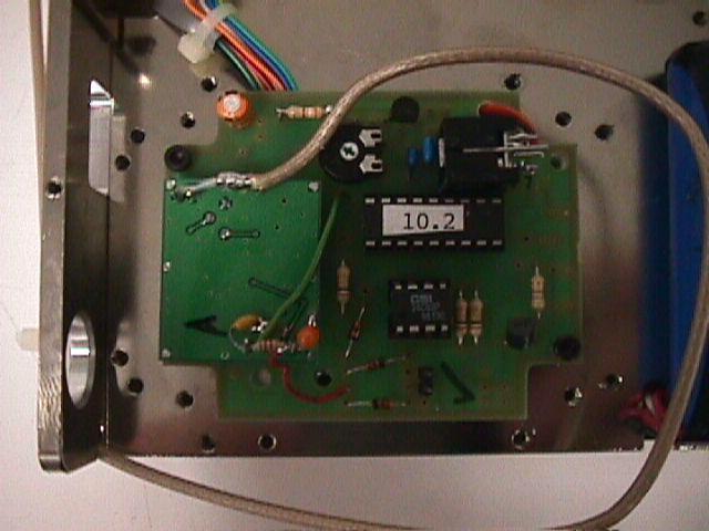
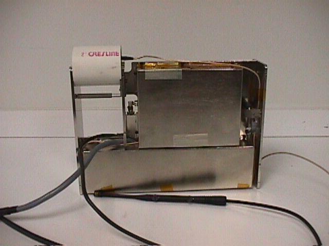
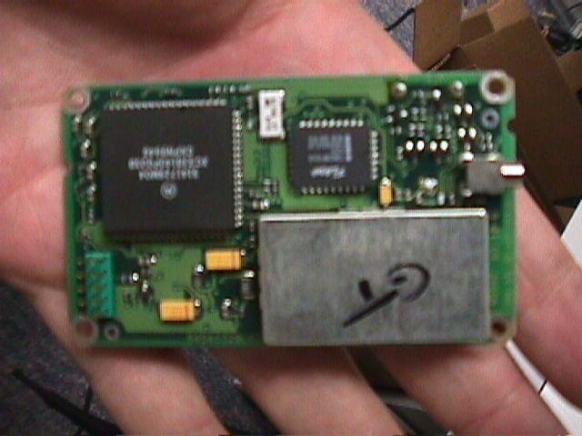
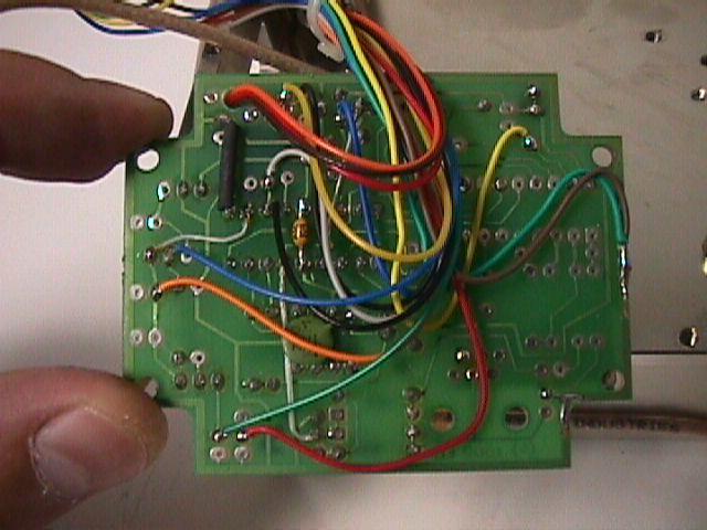
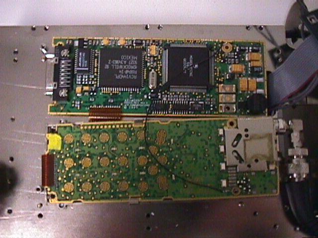
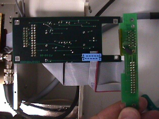
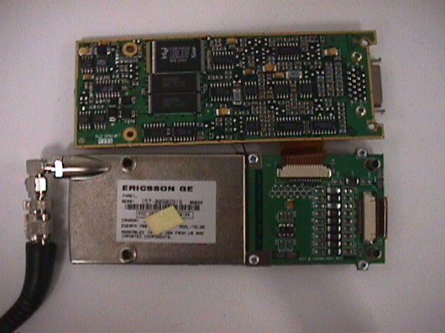
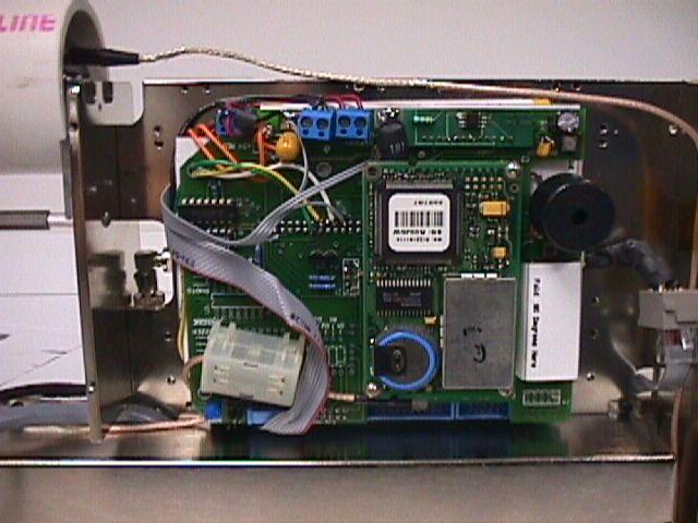
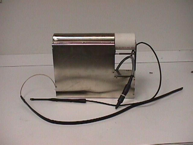
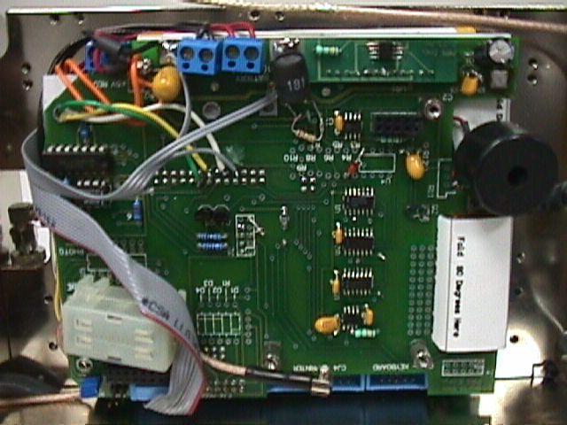
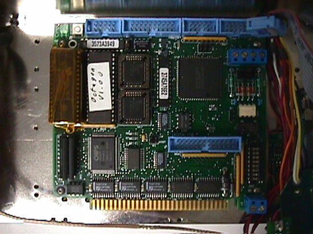
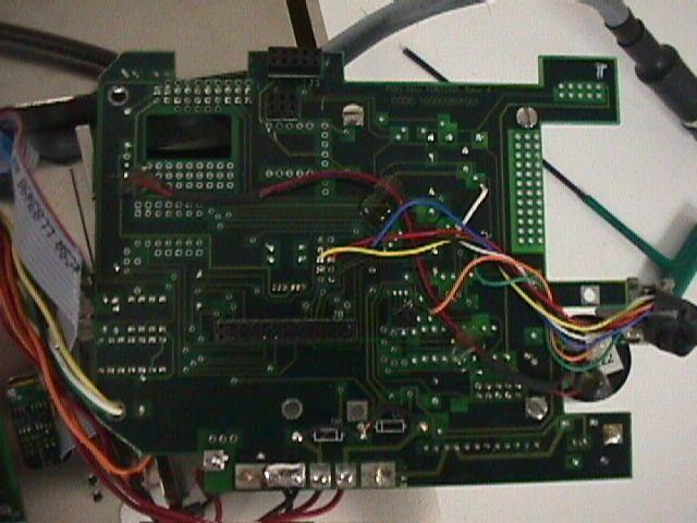
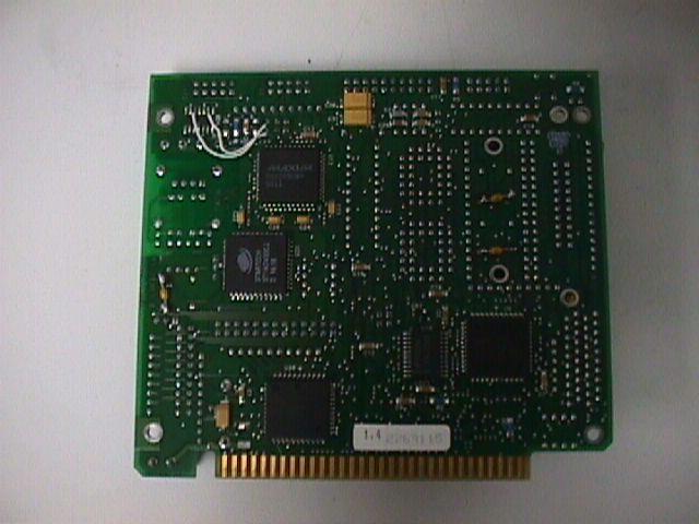
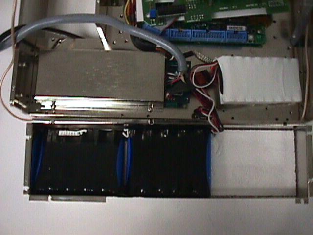
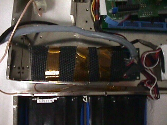
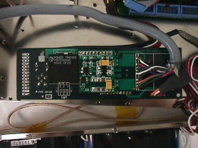
INTERNAL PHOTOGRAPHS
RF Exposure Info
i Specific Absorption Rate (SAR) Evaluation Performed on the Monitoring Device Model: 1701/1702 for Advanced Business Sciences Inc. FCC rule part 2.1093 Date of Test: October 20, 1998 Job #: J98018957a Total No. of Pages Contained in this Report: 25 + data pages This report shall not be reproduced except in full, without written approval of Intertek Testing Services. This report must not be used to claim product endorsement by NVLAP or any agency of the U.S. Government. The results contained in this report were derived from measurements performed on the identified test samples. Any implied performance of other samples on this report is dependent on the representative of the samples tested. FCC SAR and ANSI C63.4-1992, Rev. 6/97 ii VERIFICATION OF COMPLIANCE Report No. J98018957a Verification is hereby issued to the named APPLICANT and is VALID ONLY for the equipment tested hereon for use under the rules and regulations listed below . Equipment Under Test (EUT):Monitoring Device Trade Name:ABS Comtrak PTU TM Model No.:1701/1702 Serial No.:Not Labeled FCC ID:OAM1701 Applicant:Advanced Business Sciences Inc. Contact:Donald E. Reiner Address:3345 N 107th Street Omaha, Nebraska 68134, Tel. number:(800) 218-8057 Fax. number:(402) 498-8812 Applicable Regulation:FCC rule part 2.1093, FCC Docket 96-326 & Supplement C to OET Bulletin 65 Exposure Class:General Population/Uncontrolled Exposure Test Site Location:Intertek Testing Services 1365 Adams Court Menlo Park, CA 94025, USA Date of Test:October 20, 1998 Based on the test results, the tested sample was found to be in compliance with the FCC requirements for Human Exposure to Radio frequency Emissions. We attest to the accuracy of this report: Ollie MoyrongC. K. Li Test EngineerEngineering Manager A 1365 Adams Court, Menlo Park, CA 94025 Advanced Business Sciences Inc.Monitoring Device FCC ID: OAM170102Date of Test: October 20, 1998 Report # J98018957aFCC SAR Evaluationiii Table of Contents 1.0INTRODUCTION....................................................1 2.0DESCRIPTION OF EQUIPMENT.......................................1 3.0TEST SUMMARY....................................................1 4.0SYSTEM TEST CONFIGURATION...............................2 4.1Support Equipment.............................................2 4.2Block Diagram of Test Setup......................................2 4.3Test Position...................................................3 4.4Test Condition.................................................3 4.5Modifications Required for Compliance.............................4 4.6Additions, deviations and exclusions from standards...................4 5.0SAR EVALUATION..................................................4 5.1SAR Limits....................................................4 5.2Configuration Photographs.......................................5 5.2Configuration Photographs.......................................6 5.4Evaluation Procedures...........................................7 5.5Test Results....................................................7 6.0TEST EQUIPMENT.................................................10 6.1Equipment List................................................10 6.2Muscle Tissue Simulating Liquid.................................11 6.3E-Field Probe Calibration.......................................11 6.4Measurement Uncertainty.......................................12 6.5Measurement Traceability.......................................12 7.0WARNING LABEL INFORMATION - USA.............................13 8.0REFERENCES.....................................................13 APPENDIX A - SAR Evaluation Data.........................................14 APPENDIX B - Antenna Specifications........................................18 APPENDIX C - E-Field Probe Calibration Data.................................19 A 1365 Adams Court, Menlo Park, CA 94025 Advanced Business Sciences Inc.Monitoring Device FCC ID: OAM170102Date of Test: October 20, 1998 Report # J98018957aFCC SAR Evaluation 1 of 25 1.0INTRODUCTION This measurement report is designed to show compliance with the FCC part 2.1093, ET Docket 96-326 Rules for mobile and portable devices. The test procedures, as described in American National Standards Institute C95.1-1992[1] and FCC OET Bulletin 65-1997[2], were employed. A description of the product and operating configuration, the various provisions of the rules, the methods for determining compliance, and a detailed summary of the results are included within this test report. 2.0DESCRIPTION OF EQUIPMENT Equipment Monitoring Device Trade NameABS Comtrak PTUModel No.1701/1702 TM FCC IDOAM1701S/N No.Not Labelled CategoryPortableRF ExposureUncontrolled Environment Frequency 824-849 MHz EUT Antenna Description TypeMonopoleConfigurationFixed Dimensions (L)116.54 mm,(N)14.45 mmGain 0 dBi LocationMounted inside the center of the bag’s shoulder strap A preproduction version of the sample was provided by Advanced Business Sciences Inc. and received on August 3, 1998 in good working condition. 3.0TEST SUMMARY The maximum spatial peak SAR value averaged over 1g of tissue found in all tested configurations was: Measurement Summary SARMeasured Antenna OutputAntennaUsageFCC LimitsResults 1g (mW/g)Power(mW/g) (dbm) 0.61424.8ExtendedMiddle1.6Pass* Phantom * worst case uncertainty not included EUT Antenna EUT Main Chassis 0.6m (s) A 1365 Adams Court, Menlo Park, CA 94025 Advanced Business Sciences Inc.Monitoring Device FCC ID: OAM170102Date of Test: October 20, 1998 Report # J98018957aFCC SAR Evaluation 2 of 25 4.0SYSTEM TEST CONFIGURATION 4.1Support Equipment None. 4.2Block Diagram of Test Setup (s): Shielded Cable A 1365 Adams Court, Menlo Park, CA 94025 Advanced Business Sciences Inc.Monitoring Device FCC ID: OAM170102Date of Test: October 20, 1998 Report # J98018957aFCC SAR Evaluation 3 of 25 4.3Test Position The EUT was configured for testing in a typical fashion (as a customer would normally use it), and in the confines as out…
Text truncated - open the document above for the full version.
RF Exposure Info
May 19, 1999 Federal Communications Commission Application Processing Branch 7435 Oakland Mills Road Columbia, MD 21046 Attention: Frank Coperich/Kwok Chan Reference: Advanced Business Sciences Application, Ref # 7183 FCC ID: OAM170102 Confirmation #EA93180 Gentlemen: This is in response to the letters dated 4/7/99 and 4/13/99. For Item 1, the 240 mW ERP is okay. I also have received the answers from our client, Advanced Business Sciences regarding the Items 2, 3, & 4 questions. Please refer to the attached pages. Should you need more or have questions, please contact C.K. Li of our engineering department, email address is [email protected] or call at (650) 463-2922. Thanks and regards, Gaspara Lim Gcl/ Enclosures
Test Report
i FCC Part 22 Type Acceptance Performed on the Monitoring Device Model Nos.: 1701/1702 for Advanced Business Sciences Inc. FCC ID: OAM170102 Date of Test: October 19, 1998 Report #: J98018957 Total No. of Pages Contained in this Report: 22 This report shall not be reproduced except in full, without written approval of Intertek Testing Services. This report must not be used to claim product endorsement by NVLAP or any agency of the U.S. Government. The results contained in this report were derived from measurements performed on the identified test samples. Any implied performance of other samples on this report is dependent on the representative of the samples tested. FCC Part 22 Type Acceptance, ver 7/98 A 1365 Adams Court, Menlo Park, CA 94025 Advanced Business Sciences Inc., Monitoring DeviceDate of Test: October 19, 1998 FCC ID: OAM170102 Report # J98018957FCC Part 22ii Table of Contents 1.0Introduction.........................................................1 1.1Test Summary..................................................1 1.2Product Description..............................................2 1.3Related Submittal(s) Grants........................................2 2.0RF Power Output.....................................................4 2.1Test Procedure..................................................4 2.2Test Equipment.................................................4 2.3Test Results....................................................4 3.0Effective Radiated Power..............................................8 3.1Test Procedure..................................................8 3.2Test Equipment.................................................8 3.3Test Results....................................................8 4.0Modulation Deviation Limiting..........................................9 4.1Test Procedure..................................................9 4.2Test Equipment.................................................9 4.3Test Results....................................................9 5.0Audio Filter Characteristics...........................................10 5.1Test Procedure.................................................10 5.2Test Equipment................................................10 5.3Test Results...................................................11 6.0Emission Limitations, Occupied Bandwidth..............................12 6.1Test Procedure.................................................12 6.2Test Equipment................................................13 6.3Test Results...................................................13 Out of Band Emissions at Antenna Terminals...................................14 7.1Test Procedure.................................................14 7.2Test Equipment................................................14 7.3Test Results...................................................14 8.0Field Strength of Spurious Radiation....................................15 8.1Test Procedure.................................................15 8.2Test Equipment................................................15 A 1365 Adams Court, Menlo Park, CA 94025 Advanced Business Sciences Inc., Monitoring DeviceDate of Test: October 19, 1998 FCC ID: OAM170102 Report # J98018957FCC Part 22iii 8.3Test Results...................................................15 9.0Line Conducted Emissions............................................20 9.1Test Procedure.................................................20 9.2Test Results...................................................20 10.0Frequency Stability vs Temperature.....................................21 10.1Test Procedure.................................................21 10.2Test Equipment................................................21 10.3Test Results...................................................21 11.0Frequency Stability vs Voltage.........................................22 11.1Test Procedure.................................................22 11.2Test Equipment................................................22 11.3Test Results...................................................22 A 1365 Adams Court, Menlo Park, CA 94025 Advanced Business Sciences Inc., Monitoring DeviceDate of Test: October 19, 1998 FCC ID: OAM170102 Report # J98018957FCC Part 221 1.0Introduction 1.1Test Summary FCC RULEDESCRIPTION OF TESTRESULTPAGE 2.985RF Power OutputPass3 22.913Effective Radiated PowerN/A7 2.987Modulation RequirementsN/A8 22.915(d)(1)Audio Filter CharacteristicsN/A9 2.989©Emission Limitation, Occupied BandwidthN/A11 22.917(b)(d) 22.917(e)Out of Band Emissions at Antenna TerminalsN/A13 22.917(f)Mobile Emissions In Base Frequency Range 2.993Field Strength of Spurious RadiationPass14 15.107Line Conducted EmissionsPass20 2.995(a)Frequency Stability vs. TemperatureN/A22 2.995(d)(2)Frequency Stability vs. VoltageN/A23 2.1091, 2.1093Specific Absorption RatePass See SAR Report Tested By: 11/2/99 Ollie MoyrongDate Test Engineer 11/2/99 Approved By: David Chernomordik EMC Site Manager Date A 1365 Adams Court, Menlo Park, CA 94025 Advanced Business Sciences Inc., Monitoring DeviceDate of Test: October 19, 1998 FCC ID: OAM170102 Report # J98018957FCC Part 222 1.2Product Description The ABS 1701 is a device that provides law enforcement institutions and other authorities the tools which enable the monitoring of their client’s real time compliance to defined limits of time and location. Whether quantity (>1) production is [X] Yes planned Frequency Range824 - 849 MHZ Antenna(e) & GainMonopole, 0 dBi Detachable antenna ?[X] No External input[X] Digital Data 1.3Related Submittal(s) Grants [X] Cell module certified already certified. Applicant: Ericsson, Inc. FCC ID: AXATR-324-A2 Date of Grant: July 30, 1993 [X]DOC for computer section, a separate DOC is prepared. A 1365 Adams Court, Menlo Park, CA 94025 Advanced Business Sciences Inc., Monitoring DeviceDate of Test: October 19, 1998 FCC ID: OAM170102 Report # J98018957FCC Part 223 2.0RF Power Output, …
Text truncated - open the document above for the full version.
Test Setup Photos
Test Configuration Set up (Radiated) Test Configuration Set up (Line Conducted) 9.3Test Results - Line Conducted Emissions Refer to the attached data sheets. Test Result: Passes 10.0Frequency Stability vs Temperature, FCC § 2.995(a), § 22.355 Frequency Tolerance: ±2.5 ppm 10.1 Test Procedure The equipment under test was connected to an external DC power supply and the RF output was connected to a frequency counter via feedthrough attenuators. The EUT was placed inside the temperature chamber. The DC leads, RF output cable, and external PTT cable exited the chamber through an opening made for that purpose. After the temperature stabilized for approximately 20 minutes, the external PTT switch was activated, and the frequency output was recorded from the counter. 10.2 Test Equipment Temperature Chamber, -50C to +100C Hewlett Packard 5383A Frequency Counter Goldstar DC Power Supply, GR303 Rohde & Schwarz ESVP Test Receiver 10.3 Test Results Test was not performed. Cell module already certified. FCC ID: KXGAC101 and FCC ID: AXATR-324-A2. 11.0Frequency Stability vs Voltage, FCC § 2.995(d)(2), § 22.355 Frequency Tolerance: ±2.5 ppm 11.1 Test Procedure An external variable DC power supply was connected to the battery terminals of the equipment under test. The voltage was set to 115% of the nominal value and was then decreased until the transmitter light no longer illuminates; i.e., the battery end point. The output frequency was recorded for each battery voltage. 11.2 Test Equipment Hewlett Packard 5383A Frequency Counter DC Power Supply Rohde & Schwarz ESVP Test Receiver 11.3 Test Results. Test was not performed. Cell module already certified. FCC ID: KXGAC101 and FCC ID: AXATR-324-A2. Appendix A - Exhibits 1.Authorization Letter 2.Confidential Letter 3.Test Configuration Setup 4.Photographs 5.FCC Label 6.FCC Label Location 7.Block Diagram 8.Circuit Diagram 9.Theory of Operation & Tune Up Procedure 10. ESN Protection Guidelines 11. SAR Measurement Test Report 12. Users Manual
Contact Information
Applicant
Bill Johnson(President)
Technical Contact
Intertek Testing ServicesDavid Chernomordik
(650) 463-2900
1365 Adams Court · Menlo Park, California · United States
Non-Technical Contact
Advanced Business Sciences Inc.Donald Reiner
(800) 218-8057
Test Firm
Intertek Testing Services NA Inc.John Quigley
Technical Specifications
| # | Rule Parts | Frequency Range | Power Output | Emission | Tolerance |
|---|---|---|---|---|---|
| 2 | 22H | 824 MHz - 849 MHz | 240.00 mW | 40K0F8W | 2.5 ppm |
Other Applications from Corrisoft
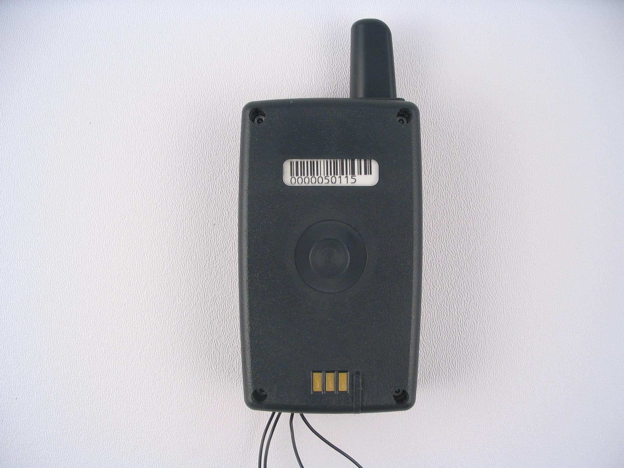
OAM5000
Sep 16, 2007System 5000 PTU
Equipment Class
PCT - PCS Licensed Transmitter worn on body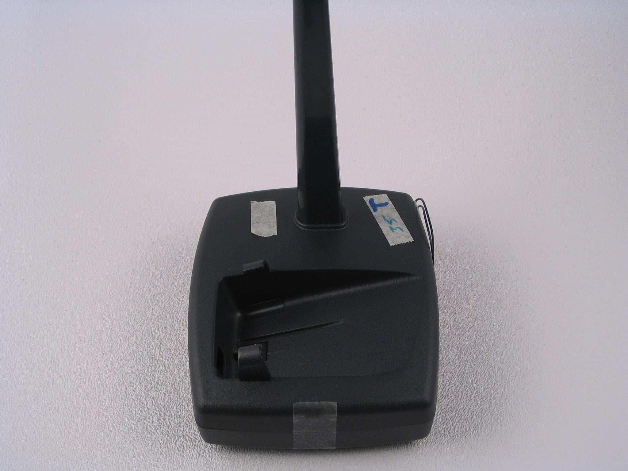
OAM5000BASE
Sep 13, 2007System 5000 Base
Equipment Class
DSC - Part 15 Security/Remote Control Transmitter
OAM2250
Mar 14, 2004Personal Tracking Device
Equipment Class
PCT - PCS Licensed Transmitter worn on body
OAM2100-433
May 20, 2003Personal Tracking Device
Equipment Class
DXT - Part 15 Low Power Transceiver, Rx Verified
OAM2100NC
Apr 29, 2002Personal Tracking Unit
Equipment Class
DXT - Part 15 Low Power Transceiver, Rx Verified