OBIC9483TXKeyless entry system for vehicle
U-shin Ltd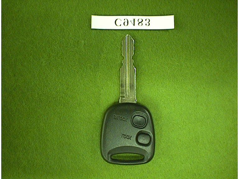
Click to zoom
Application Details
- Equipment Class
- DSC - Part 15 Security/Remote Control Transmitter
- Date of Grant
- Mar 18, 1999
- Application Purpose
- Original Equipment
- Date of Application
- Feb 04, 1999
- Equipment Note
- Keyless entry system for vehicle
- Frequency Range
- 315.00000000 - 315.00000000
- Company
- U-shin Ltd
- Country
- Japan
Documents & Files
Document Text
Text extracted from the exhibit documents filed with the FCC. Open a document above to read the original.
Users Manual
FCC ID : OBIC9483TX OWNER’S MANUAL (DRAFT) Operating instructions for this system: Keyless Entry System; will be included in the owner’s manual of the vehicle and its contents will be as follow: Keyless Entry System Function explanation 1. Door lock control A lock or unlocking state of the doors is remote-controlled by the microwave sent from the transmitter. 2. Answer back function The information of lock or unlocking of the doors by the microwave remote control can be confirmed from the sign of the room lamp. 3. Distance of operation It works within approximately 2 meters from the vehicle. Caution : The distance of operation will be affected by the electromagnetic circumstance in which this system is located, i.e. in the neighborhood of broadcasting station or power plant. 4. Burglary prevention If a door is not opened after unlocking by the transmitter, the door is automatically locked 30 seconds later. 5. Safe function When the key has been inserted into the ignition switch while the door is opened, it does not work. 6. Registration function This keyless entry system can use three transmitters for one receiver. One transmission code is registered by one registration operation. The oldest code is erased by the registration operation. When a transmitter is newly added, the registration will be made by the following procedure: FCC ID : OBIC9483TX IN DEALER (INITIAL CONDITION ; INPUT OTHER THAN IGNITION) 1. IG ON OFF, 5 TIMES 2. PRESS UNLOCK BUTTON OF NEW TRANSMITTER WITHIN 5 SECONDS. 3. AFTER A RECEIVER BECOMES PROGRAMMING MODE, BY CYCLING DOOR LOCK ONCE I.E.LOCK UNLOCK 4. PRESS UNLOCK BUTTON OF NEW TRANSMITTER WITHIN 5 SECONDS. 5. RECEIVER WILL CONFIRM PROGRAMMING BY CYCLING DOOR LOCK ONCE. I.E.LOCK/UNLOCK 6. END OF PROGRAMMING. THE REVEIVER CAN BE TAUGHT THE IDENTITIES OF AS MANY AS THREE(3) TRANSMITTERS. ONCE THE THREE MEMORY LOCATIONS ARE OCCUPIED, A NEW TRANSMITTER PROGRAMMING WILL CAUSE THE FIRST PROGRAMMED TRANSMITTER, I.E. IN THE MEMORY LOCATION TO BE ERASED. *IF THE RKE RECEIVER HAS ANOTHER INPUT DURING A SERIES OF ACTION 1-6, IT RECEASES PROGRAMMING MODE. CAUTION : When registering a new transmitter is made for the loss and so on, repeat registration operation three times for deleting the old code. The Operation Point 1. Door locking Push the lock switch on the transmitter. 2. Door unlocking Push the unlock switch on the transmitter. CAUTION : The micro wave signal sent from the transmitter is exclusive use for each product. Cautions on Handling 1.the transmitter must keep dry. 2.It causes the trouble to drop, to bump or to step on the transmitter. FCC ID : OBIC9483TX 3. Don’t leave the transmitter in high temperature place, more than 60 degrees, such as on the dashboard. The lifetime of the battery will be decline and make trouble. 4.When doing the lock/the unlocking of the door by the keyless entry confirm the condition always. If Trouble Happened Proceed through the following checklist. Should any problem consulted your sales shop or dealer. Battery Replacement When the battery of the transmitter became weak replace the battery with a new one by the following procedure. (use one coin type lithium battery CR1616). 1. Remove a screw then remove the case with pressing. 2. Install a new battery. 3. Reassemble the transmitter properly. Notice : Check the battery’s polarity as to correspond with the positive(+) and the negative( -) marks. (The upper side is +.) FCC ID : OBIC9483TX Changes or modifications not expressly approved by the manufacturer for compliance could void the user’s authority to operate the equipment. This device complies with Part 15 of the FCC Rules. Operation is subject to the following two conditions: (1)This device may not cause harmful interference, and (2)this device must accept any interference received, including interference that may cause undesired operation.
Cover Letter(s)
February 5, 1999 Federal Communications Commission Equipment Approval Services P.O.Box 358315 Pittsburgh, PA 15251-5315 U.S.A. Subject : Certification Application for Part 15 Equipment Authorization Applicant : U-shin Ltd. Product : Keyless entry system for vehicle, Transmitter Model No.: C9483 FCC ID : OBIC9483TX Dear Sir/Madame: We are submitting application documents through electronic filing for Certification of FCC Part 15 Equipment Authorization for the above-mentioned product. FCC Form 159 with a check for application fee will be mailed within a couple of days. We shall appreciate your immediate attention to this application and awaiting your approval. Sincerely K.O. Kyozo Ouchi Application Service Div. Product Safety Center Japan Quality Assurance Organization 21-25, Kinuta 1-chome, Setagaya-ku Tokyo, 157-8573 Japan FCC ID : OBIC9483TX List of Submitted Documents (02/01/1999) (1) Name and Address of the Applicant : U-shin Ltd. 5217, Nakaze, Hamakita-shi, Shizuoka, 434-0012 Japan (2) Name and Address of the Manufacturer : The same as (1) (3) FCC ID : OBIC9483TX (4) EXHIBIT A : FCC ID Label (5) EXHIBIT B : User’s Manual (6) EXHIBIT C : Equipment Description and Brief Description of Circuit Function (7) EXHIBIT D : Circuit Diagram (8) EXHIBIT E : Report of Measurements (9) EXHIBIT F : Photographs (10) Section 2.1033 (b) (8) requirement : N/A (11) Section 2.1033 (b) (9) requirement : N/A (12) Section 2.1033 (b) (10) requirement : N/A (13) Section 2.1033 (c) requirement : N/A
External Photos
-
Operational Description
FCC ID : OBIC9483TX The Keyless Entry System for Vehicles This system is to be installed on motor vehicles as OEM item. It consists of a transmitter (C9483) and a receiver (G7071), that locks and unlocks of the car door by the remote control unit with microwave. The transmitter is very small and is integrated with an ignition key. The receiver has a coil antenna. The transmitter produces output of ID Code, Control Code and Custom Code by the lock /unlock switching as electric wave signal. The receiver drives the corresponded actuator to the control code after reception and detection of the electric signal from the transmitter. But it is unable to drive when IG is ON or the door is open.
Test Report
REPORT OF MEASUREMENTS Date : January 28, 1999 Issue in : Tokyo, Japan JQA APPLICATION NO.: 80-80627 1. Applicant : U-shin Ltd. 5217, Nakaze, Hamakita-shi, Shizuoka 434-0012, Japan 2. Manufacturer : U-shin Ltd. 5217, Nakaze, Hamakita-shi, Shizuoka 434-0012, Japan 3. Description of Equipment : Keyless Entry System (Transmitter) a) FCC ID : OBIC9483TX b) Trade Name : U-shin c) Model No. : C9483 d) Operating Frequency : 315 MHz e) Power Supply : 3 VDC 4. Applicable Rule : FCC Rules & Regulations Part 15 Subpart C (June 23, 1989) 5. Place of Measurement : JQA EMC Engineering Dept. 6. Date of Measurement : December 22, 1998 7. Total Pages of This Report : 12 (including this page) 8. I certify that I am authorized to sign for the report and that all the statement in this report and in the exhibits hereto are true and correct to the best my knowledge and belief. Shigeru Osawa, Assistant Manager Testing Div. EMC Engineering Dept. JQA Application No.: 80-80627 FCC ID : OBIC9483TX Sheet 2 of 12 sheets 1. Transmitter Fundamental and Spurious Emission: [§15.231(b)] Measurement Method Employed: Measurements were made under the conditions specified ANSI C63.4. The transmitter under test was operated continuously in its normal operating mode for the purpose of the measurements. In order to secure the continuous operation of the device under test, rewiring in the circuit was down by the manufacturer so as to affect its intended operation. The receiving antenna polarized horizontally was varied from 1 to 4 meters and the wooden turntable was rotated 360 degrees to obtain the highest reading on the field strength meter or on the display of the spectrum analyzer. And also, each emission was to be maximized by changing the orientation of the transmitter under test. The device was tested three orthogonal planes. These measurements were repeated with the receiving antenna polarized vertically. In this measurements, in order to determining the average value during a 100 ms interval of the maximum radiated power generated from the transmitter under test, the encoded waveform in the time domain was used, details of which was illustrated in the attached sheet. Measurement Results: Operating Frequency : 315 MHz Distance of Measurement : 3.0 meters Antenna Amp. Meter Reading Factor* Field Strength Frequency Factor Gain Horiz. Vert. Horiz. Vert. (MHz) (dB) (dB) (dB/uV) (dB/uV) (dB) (uV/m) (uV/m) Fundamental 315 23.0 - 46.7 44.5 -4.9 1737.8 1349.0 Harmonic Frequency 630 31.2 - 17.2 15.2 -4.9 149.6 118.9 945 36.6 - 17.1 16.0 -4.9 275.4 242.7 1260 26.7 - 24.5 22.9 -4.9 206.8 172.0 1575 29.5 - 19.9 20.6 -4.9 167.8 181.9 1890 31.1 - 19.2 17.5 -4.9 187.2 153.9 2205 33.0 46.8 50.6 49.0 -4.9 39.2 32.6 2520 33.8 46.8 60.0 60.3 -4.9 127.5 132.0 2835 35.2 46.8 50.5 52.1 -4.9 50.2 60.3 3150 36.4 46.7 49.9 49.0 -4.9 54.3 48.9 JQA Application No.: 80-80627 FCC ID : OBIC9483TX Sheet 3 of 12 sheets Note: 1. The spectrum was checked from 30 MHz to tenth harmonics. All emissions not listed were found to be more than 20 dB below the limits. 2. The symbol of “<” means “or less”. 3. The cable loss was included in the antenna factor. 4. Sample calculation : at 315 MHz 10 (AF+Mr+F)/20 = 10 (23.0+46.7-4.9)/20 = 1737.8 uV/m Where, Af = Antenna Factor including the cable loss. Mr = Meter Reading F = Peak to Average factor 5. “*”: The factor due to the pulsed waveform as shown in the attached sheets. 6. Measuring Instrument Setting: Field Strength Meter:(<1000 MHz) Detector function : Peak IF Bandwidth : 120 kHz Spectrum Analyzer:(>1000 MHz) Resolution Bandwidth : 1 MHz JQA Application No.: 80-80627 FCC ID : OBIC9483TX Sheet 4 of 12 sheets JQA Application No.: 80-80627 FCC ID : OBIC9483TX Sheet 5 of 12 sheets JQA Application No.: 80-80627 FCC ID : OBIC9483TX Sheet 6 of 12 sheets MESUREMENT SET-UP FOR UP TO 1 GHz Turn Table EUT 3 m 1 m 0.8 m Half-wave Dipole Antenna Field Strength Meter Ground Plane 4 m MESUREMENT SET-UP FOR ABOVE 1 GHz Turn Table EUT 3 m 1 m 0.8 m Log-periodic Antenna Spectrum Analyzer Ground Plane 4 m JQA Application No.: 80-80627 FCC ID : OBIC9483TX Sheet 7 of 12 sheets Horizontal Plane Vertical Plane JQA Application No.: 80-80627 FCC ID : OBIC9483TX Sheet 8 of 12 sheets 2. Emission Limitation: [§15.231(c)] Measurement Method Employed: By using a spectrum analyzer with a vertical antenna for picking up the signal, the measurements of the fundamental frequency were made under the following transmitting modes of the EUT. Measurements Results : Specified Limits: 0.25 % of the Fundamental Frequency 315 MHz x 0.0025 = 787.5 kHz Refer to the attached graphs. JQA Application No.: 80-80627 FCC ID : OBIC9483TX Sheet 9 of 12 sheets JQA Application No.: 80-80627 FCC ID : OBIC9483TX Sheet 10 of 12 sheets JQA Application No.: 80-80627 FCC ID : OBIC9483TX Sheet 11 of 12 sheets MESUREMENT SET-UP FOR BAND WIDTH EUT Approximately 6 inches 0.8 m Spectrum Analyzer Vertical Antenna Test Table JQA Application No.: 80-80627 FCC ID : OBIC9483TX Sheet 12 of 12 sheets LIST OF MEASUREMENT EQUIPMENT Equipment (Model No.) Manufacturer Date of Cal. 1. Field Strength Meter ESVP Rohde & Schwarz May 1998 2. Spectrum Analyzer 8566B Hewlett Packard Inc. April 1998 3. Tuned Dipole Antenna KBA-511 Kyoritsu Electrical Works November 1998 KBA-611 Kyoritsu Electrical Works November 1998 4. Vertical Antenna 91972-2 Stoddard Aircraft Radio - Co., Ltd. 5. Log-periodic Antenna HL 025 Rohde & Schwarz November 1998
Contact Information
Applicant
Satoru Gokuda(Acting Executive Manager design Dept.2)
Technical Contact
Japan Quality Assurance Org.Takaharu Hada
[email protected]+81 3 3416 0193
21-25, Kinuta 1-chome, · Tokyo · Japan
Non-Technical Contact
Japan Quality Assurance Org.Kyozo Ouchi
[email protected]+81 3 3416 0174
Test Firm
Japan Quality Assurance Org.Tetsuo Kato
Technical Specifications
| # | Rule Parts | Frequency Range | Power Output |
|---|---|---|---|
| 1 | 15C | 315 MHz - 315 MHz | - |
Other Applications from U-shin Ltd
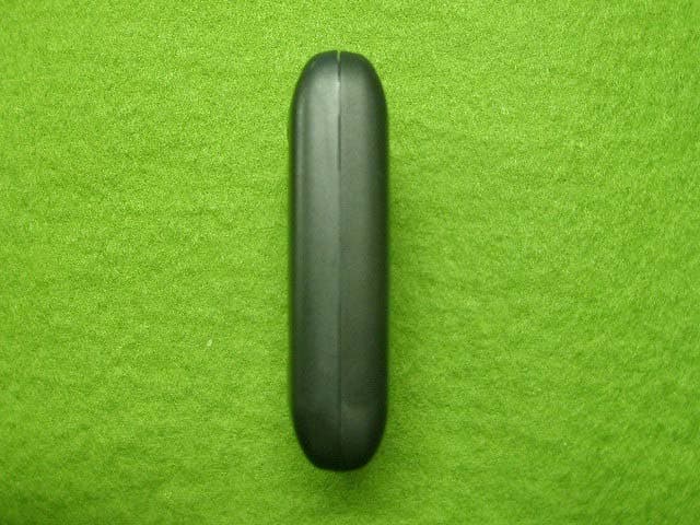
OBIH7079TX
Jun 13, 2010Transmitter, Keyless Entry
Equipment Class
DSR - Part 15 Remote Control/Security Device Transceiver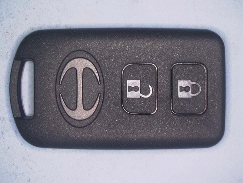
OBIWRDCE0050TX
Jan 30, 2010Switch Assy, Door Control
Equipment Class
DSR - Part 15 Remote Control/Security Device Transceiver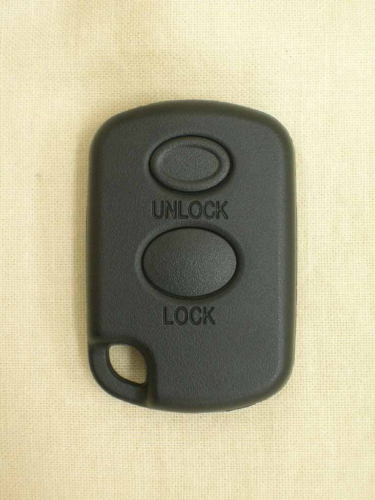
OBIH7027TX
Oct 09, 2006Keyless Entry System Transmitter
Equipment Class
DSC - Part 15 Security/Remote Control Transmitter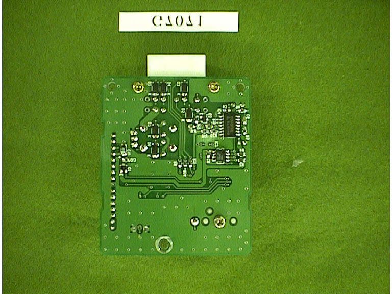
OBIG7071RX
Mar 16, 1999Keyless Entry Receiver for Vehicle
Equipment Class
CYY - Communications Receiver used w/Pt 15 Transmitter