OBIH7027TXKeyless Entry System Transmitter
U-shin Ltd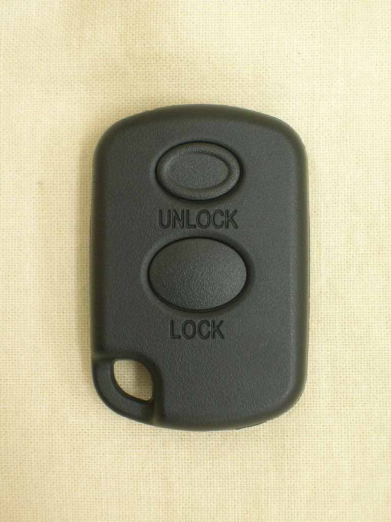
Click to zoom
Application Details
- Equipment Class
- DSC - Part 15 Security/Remote Control Transmitter
- Date of Grant
- Oct 09, 2006
- Application Purpose
- Original Equipment
- Date of Application
- Oct 09, 2006
- Equipment Note
- Keyless Entry System Transmitter
- Frequency Range
- 315.00000000 - 315.00000000
- Company
- U-shin Ltd
- Country
- Japan
Documents & Files
Document Text
Text extracted from the exhibit documents filed with the FCC. Open a document above to read the original.
Users Manual
Page 1 of 4 OWNER’S MANUAL Keyless Entry System Transmitter & Receiver Trade Name : U-shin Model Number : H7027*-00-00 (Transmitter), H7028*-00-00 (Receiver) FCC ID : OBIH7027TX (Transmitter) IC : 3313-H7027TX (Transmitter), 3313-H7028RX (Receiver) Operating instructions for this system: Keyless Entry System; will be included in the owner’s manual of the vehicle and its contents will be as follow: Function explanation 1. Door lock control A lock or unlocking state of the doors is remote-controlled by the micro wave sent from the transmitter. And a lock or unlocking state of the doors is controlled by the central door lock switch in the vehicle. 2. Answer back function The information of lock or unlocking of the doors by the micro wave remote control can be confirmed from the sign of the room lamp and the hazard lamp. 3. Distance of keyless entry operation It works within approximately 3 meters from the cabin center. Caution : The distance of operation will be affected by the electromagnetic circumstance in which this system is located, i.e. in the neighborhood of broadcasting station or power plant. 4. Burglary prevention If a door is not opened after unlocking by the transmitter, the door is automatically locked 30 seconds later. 5. Safe function When the starter key has been inserted into the starter switch or the door is opened, keyless entry system does not work. 6. Function to prevent for the starter key from being shut into the cabin When the starter key has been inserted into the starter switch, the door is not locked for prevent for the starter key from being shut into the cabin. 7. Registration function This keyless entry system can use three transmitters for one receiver. One transmission code is registered by one registration operation. The oldest code is erased by the registration operation. When a transmitter is newly added, the registration will be made by the following procedure: REGISTRATION METHOD 1. REGISTRATION OPERATION START (STARTER KEY IS PULLED OUT, CONDITION OF ALL DOOR CLOSE.) 2. OPENNING ONLY DRIVER'S SIDE DOOR. Page 2 of 4 3. IT IS TAKEN ON CONDITION FOR OPERATION SW OF TRANSMITTER THAT WANTS TO REGISTER MAX.10s AFTER IT OPENED DOOR. (EITHER OF LOCK AND UNLOCK IS POSSIBLE.) 4. STARTER KEY IS PUT IN STARTER SW AND IT IS ON CONDITION OF STARTER SW (M CONTACT), IN CASE OF REGISTRATION LESS THAN 10s AFTER OPENNING DRIVER'S SIDE DOOR. 5. IT IS OFF CONDITION OF STARTER SW (M CONTACT), AND STARTER KEY IS PULLED OUT IN CASE OF REGISTRATION LESS THAN 10s AFTER STARTER SW (M CONTACT) IS ON CONDITION. 6. REPEAT MORE THAN SIX TIMES OF DOOR LOCK ON AND OFF BY DRIVER'S SIDE DOOR SW ON AND OFF LESS THAN 30s FROM M CONTACT OFF CONDITION. 7. TRANSMITTER UNLOCK SW FOR REGISTRATION IS KEEPING ON TILL DOOR LOCK IS OPERATED (MORE THAN 5s) LESS THAN 5s AFTER TWO TIMES OF DOOR LOCK ON AND OFF. 8. REGISTRATION COMPLETION *IF THE RKE RECEIVER HAS ANOTHER INPUT DURING A SERIES OF ACTION 1-8, IT RECEASES REGISTRATION MODE. Caution : When registering a new transmitter is made for the loss and so on, repeat registration operation three times for deleting the old code. The Operation Point 1. Keyless entry operation (1) Door locking Push the lock switch on the transmitter. (2) Door unlocking ①Driver’s side door unlocking Push the unlock switch on the transmitter. ②Other doors unlocking Push the unlock switch on the transmitter again within 5 seconds after ① operation. Caution : The micro wave signal sent from the transmitter is exclusive use for each product. 2. Central door lock switch operation (1) Door locking Push the lock switch on central door lock. (2) Door unlocking Push the unlock switch on central door lock. Page 3 of 4 Cautions on Handling 1. The transmitter must keep dry. 2. It causes the trouble to drop, to bump or to step on the transmitter. 3. Don’t leave the transmitter in high temperature place, more than 60 degrees, such as on the dashboard. The lifetime of the battery will be decline and make trouble. 4.When doing the lock/the unlocking of the door by the keyless entry confirm the condition always. If Trouble Happened Proceed through the following checklist. Should any problem consulted your sales shop or dealer. Battery Replacement When the battery of the transmitter became weak replace the battery with a new one by the following procedure. ( use one coin type lithium battery CR2032 ) 1. Remove a screw. 2. Hold a case then divide a ditch of circumference up and down and take it off. The upper side : The side of operation switches The bottom side : The side of label pasting (When it is hard to come off, insert a minus screwdriver in a ditch of circumference, and please remove it.) 3. Install a new battery. (A battery is fitted in a case of bottom side.) 4. Reassemble the transmitter properly. Notice : Check the battery’s polarity as to correspond with the positive(+) and the negative( -) marks. Is a starter key inserted in the starter switch?Pull out a starter key. Are all doors closed surely?Close all doors. Consult the sales shop of the finding. YES NO NO YES Page 4 of 4 This device complies with part 15 of the FCC Rules and RSS-210. Operation is subject to the following two conditions: (1) This device may not cause harmful interference, and (2) this device must accept any interference received, including interference that may cause undesired operation. Caution Changes or modifications not expressly approved by U-shin could void the FCC compliance and negate your authority to operate the product.
External Photos
Page 1 of 5 Model: H7027*-00-00 FCC ID: OBIH7027TX IC: 3313-H7027TX External Photographs of the Transmitter External Front View Photograph Page 2 of 5 Model: H7027*-00-00 FCC ID: OBIH7027TX IC: 3313-H7027TX External Rear View Photograph
ID Label/Location Info
Page 1 of 1 Model: H7027*-00-00 FCC ID: OBIH7027TX IC: 3313-H7027TX Label & Location Keyless Entry System Transmitter for Vehicles Trade Name: U-shin Model Number: H7027*-00-00 FCC ID: OBIH7027TX CANADA: 3313-H7027TX
Internal Photos
Page 3 of 5 Model: H7027*-00-00 FCC ID: OBIH7027TX IC: 3313-H7027TX Internal Photographs of the Transmitter Internal Upper Side Photograph Page 4 of 5 Model: H7027*-00-00 FCC ID: OBIH7027TX IC: 3313-H7027TX Internal Lower Side Photograph Page 5 of 5 Model: H7027*-00-00 FCC ID: OBIH7027TX IC: 3313-H7027TX The Position of the Battery Photograph
Test Report
Page 1 of 16 FCC ID: OBIH7027TX Report Form: FCC_ver.1_Rev.06-09 Originator: IPS Corporation MEASUREMENT / TECNICAL REPORT Applicant : U-shin Ltd. 5217, Nakaze, Hamamatsu-shi, Shizuoka-ken,434-0012, Japan Kind of Equipment : Keyless Entry System Transmitter for Vehicles Trademark : U-shin Model Number : H7027*-00-00 Standards : Federal Communication Commission Rules & Regulations Part 15 C Date Received : September 11, 2006 Date Tasted : September 11, 2006 – September 21, 2006 Date Report Issued : September 27, 2006 Report Number : EMCV06914 The measurements covered by this document have been performed in accordance with NVLAP requirements, which include the requirements of ISO/IEC 17025:1999 and are traceable to national or international standards of measurement. This report summarizes the result of a signal investigation performed on the described test object and test results relate only to tested sample. The report shall not be reproduced except in full without the written approval of the IPS Corporation. TESTED SUPERVISED BY : Mikitomo Horigane APPROVED BY : Nobuyuki Kuwazawa / Manager IPS Corporation 1878-1 Harumiya Ono Tatsuno-machi, Kamiina-gun, Nagano-ken, 399-0601, Japan. Phone: +81-266-44-5200 Fax: +81-266-44-5300 URL: http://www.ips-emc.co.jp Page 2 of 16 Report No. EMCV06914 Model: H7027*-00-00 FCC ID: OBIH7027TX Report Form: FCC_ver.1_Rev06-09 Originator: IPS Corporation Table of contents 1 Introduction 3 2 Test laboratory 3 3 Applicant information 3 4 Product description 3 5 Test result 4 6 Operation description 4 6.1 Test System Details 4 6.2 EUT configuration and measurement description 4 6.3 Configuration of Tested System 5 7 Radiated emissions 5 7.1 Test Facility 5 7.2 Description of Measurement Procedure 5 7.3 Radiated emissions test frequency and characteristics 6 7.4 Instrumentation 7 7.5 Field Strength Calculation 8 7.6 Measurement Data 8 8 Bandwidth 13 8.1 Regulation 13 8.2 Calculation of the 20 dB bandwidth limit 13 8.3 Test Result 13 8.4 Measurement Data 13 9 Periodic operation characteristics 14 9.1 Regulation 14 9.2 Test Result 14 9.3 Measurement Data 14 10 Test Configuration Photo 15 Page 3 of 16 Report No. EMCV06914 Model: H7027*-00-00 FCC ID: OBIH7027TX Report Form: FCC_ver.1_Rev06-09 Originator: IPS Corporation 1 Introduction U-shin model H7027*-00-00 was tested for compliance with FCC Regulation Part 15, subpart C. The tests were performed at the IPS Corporation, Test Range following the procedures described in ANSI C63.4-2003 “Methods of Measurement of Radio-Noise Emissions from Low-Voltage Electrical Equipment in the Range of 9 kHz to 40GHz” 2 Test laboratory Company name : IPS Corporation Address : 1878-1 Harumiya Ono Tatsuno-machi Kamiina-gun 399-0601 Country : Japan Test Facility : EMC Center (NVLAP Code: 200012-0, FCC Registration Number: 93663) Phone : +81-266-44-5200 Fax : +81-266-44-5300 Web : http://www.ips-emc.co.jp 3 Applicant Information Company name : U-shin Ltd. Address : 5217, Nakaze, Hamamatsu-shi, Shizuoka-ken, 434-0012 Country : Japan Phone : +81-53-588-4600 Fax : +81-53-588-4603 Web : http://www.u-shin.co.jp 4 Product Description Samples of the following apparatus were submitted for testing: Type of equipment : Keyless Entry System Transmitter for Vehicles Category : Security Remote Control Model No. : H7027*-00-00 Operating Frequency : 315 MHz Highest Frequency used in the EUT : 315 MHz Lowest Frequency used in the EUT : 1 MHz Method of Frequency Generation : Crystal (for 315 MHz) Power Rating : DC 3.0V (Battery) *1 Product Type : Pre-Production Serial No. : No.11 FCC ID : OBIH7027TX Note: *1 - This test was Performed with the new battery. Page 4 of 16 Report No. EMCV06914 Model: H7027*-00-00 FCC ID: OBIH7027TX Report Form: FCC_ver.1_Rev06-09 Originator: IPS Corporation 5 Test result Test Specification : FCC Part15 Subpart C: 2005 Test Procedure : ANSI C63.4: 2003 FCC Section Requirements Test result 15.231 (b) Field Strength of Fundamental Emission Pass 15.205 (b) 15.209 Radiated Spurious Emission Pass 15.207 (a) Conducted Emission N/A *1 15.231 (a) (1) Periodic operation characteristics Pass 15.231 (c) Bandwidth of the Emission (20 dB bandwidth) Pass Note: *1 – This test is not applicable since the EUT does not have AC power port. 6 Operation description 6.1 Tested System Details EUT Manufacturer Model No.Serial No.Note AKeyless Entry System TransmitterU-shinH7027*-00-00No.11Power used battery*1 Equipment Note: *1 Battery - Manufacturer : Panasonic Type : CR2032 The Tested System dose not have peripherals and cable. 6.2 EUT configuration and measurement description The EUT is a 315MHz transmitter. The device is actuated via mechanical keys, and contains an antenna on the PCB. Therefore, the equipment complies with the antenna requirement (FCC part 15.203). During Emission tests the EUT was operated in the continuous transmitting for worst emission investigation. This test were performed with no deviation from the ANSI C63.4-2003 There were no modifications made to the EUT by IPS Corp. Page 5 of 16 Report No. EMCV06914 Model: H7027*-00-00 FCC ID: OBIH7027TX Report Form: FCC_ver.1_Rev06-09 Originator: IPS Corporation 6.3 Configuration of Tested System A Table size: 0.8(H)*2.0(W)*1.0(D) Semi-anechoic Chamber Note: This figure shows Radiated Emission Test as a representative figure. Refer to figure / photos of each test for actual test arrangement. 7 Radiated emissions 7.1 Test Facility Test Facility located at EMC Center of IPS Corporation. -No.2 and No.3 semi - anechoic chamber (NVLAP Code: 200012-0, FCC Registration Number: 93663) 7.2 Description of Measurement Procedure The test was made according to ANSI C63.4: 2003 on the semi-anechoic chamber, which is 3 m distance measurement. The test performed in 3m of distance from EUT to an antenna. The EUT is placed on a turntable which is 0.8m above the ground. The antenna to ground distance was adjusted between 1 m to 4 m in height above 30 MHz measurement. Exploratory test - EUT and syste…
Text truncated - open the document above for the full version.
Test Setup Photos
Page 15 of 16 Report No. EMCV06914 Model: H7027*-00-00 FCC ID: OBIH7027TX Report Form: FCC_ver.1_Rev06-09 Originator: IPS Corporation 10 Test Configuration Photo [ X axis ] [ Y axis ] [ Z axis ] Page 16 of 16 Report No. EMCV06914 Model: H7027*-00-00 FCC ID: OBIH7027TX Report Form: FCC_ver.1_Rev06-09 Originator: IPS Corporation 10 Test Configuration Photo (continue) [ Frequency Range: 1 MHz to 30 MHz ] [ Frequency Range: 30 MHz to 3150 MHz ]
Contact Information
Applicant
Satoru Gokuda(Acting Executive Manager design Dept.2)
Technical Contact
PCTEST Engineering Laboratory, Inc.Randy Ortanez
[email protected]410-290-6652
6660-B Dobbin Road · Columbia, Maryland · United States
Test Firm
IPS CorporationOsamu Kubota
Technical Specifications
| # | Rule Parts | Frequency Range | Power Output |
|---|---|---|---|
| 1 | 15.231 | 315 MHz - 315 MHz | - |
Other Applications from U-shin Ltd
OBIH7079TX
Jun 13, 2010Transmitter, Keyless Entry
Equipment Class
DSR - Part 15 Remote Control/Security Device Transceiver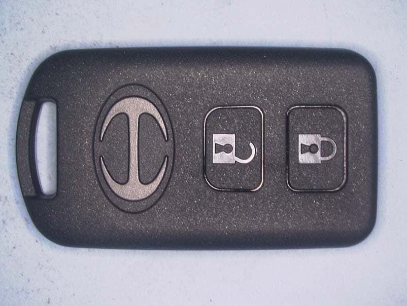
OBIWRDCE0050TX
Jan 30, 2010Switch Assy, Door Control
Equipment Class
DSR - Part 15 Remote Control/Security Device Transceiver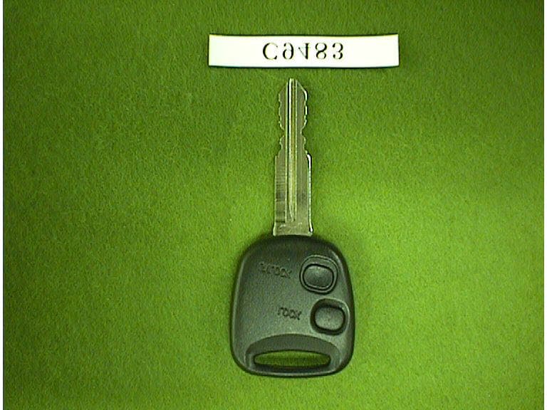
OBIC9483TX
Mar 18, 1999Keyless entry system for vehicle
Equipment Class
DSC - Part 15 Security/Remote Control Transmitter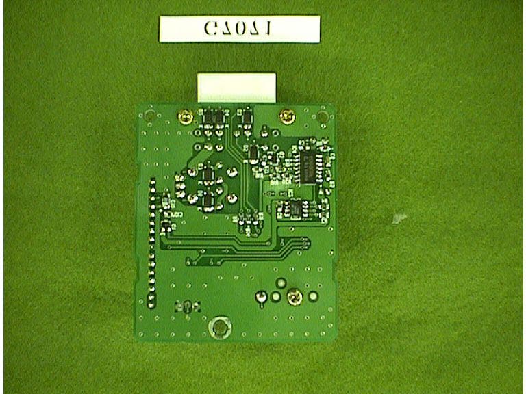
OBIG7071RX
Mar 16, 1999Keyless Entry Receiver for Vehicle
Equipment Class
CYY - Communications Receiver used w/Pt 15 Transmitter