ODMAP60Wireless-N PoE Access Point AP60
OvisLink Corp.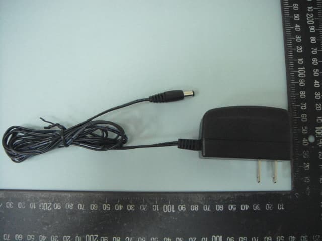
Click to zoom
Application Details
- Equipment Class
- DTS - Digital Transmission System
- Date of Grant
- Nov 01, 2011
- Application Purpose
- Original Equipment
- Date of Application
- Nov 01, 2011
- Equipment Note
- Wireless-N PoE Access Point AP60
- Frequency Range
- 2422.00000000 - 2452.00000000
- Company
- OvisLink Corp.
- Country
- Taiwan
Documents & Files
Document Text
Text extracted from the exhibit documents filed with the FCC. Open a document above to read the original.
Users Manual
P1 Português PT Noticia Importante: O modo wireless padrão é : modo "AP" O endereço IP padrão é 192.168.100.252 Por defeito a subnet mask é 255.255.255.0 O nome utilizador padrão é: admin A palavra-chave padrão é: airlive O SSID padrão é: airlive Certifique-se por favor de instalar a antena antes do power-on (ligar à energia). Caso contrário, o rádio pode ser danificado. Login Gestor Web para Configurar o AP60 1. Instale por favor a antena no AP60. 2 .Conecte o seu PC em qualquer porta LAN por cabo Ethernet. 3 .Conecte o power jack na porta power. 4 .Aguarde 1 minuto para o AP60 terminar o reboot. 5 .Por favor defina o endereço do seu PC para 192.168.100.x (ou outro endereço dentro da mesma sub-rede) 6 .Digite o endereço IP do AP60 no explorador web para entrar no login do Gestor Web. Configurar o AP60 com o setup wizard 1. Login Gestor web e seleccione o idioma no topo da barra de idiomas. (Figura A) 2. Clique em “Setup Wizard” em Wireless Settings. (Figura B) 3. Selecione Modo Wireless: O modo de operação por defeito é AP. Quando o modo estiver seleccionado, à uma confirmação em baixo e à esquerda da ilustração. Por favor escolha o modo e clique “Next”. (Figura B) 4. Wireless Settings: Configure as Definições Wireless para recursos avançados e clique “Next” depois de terminar. 5. WAN Settings: Configure as definições WAN, e seleccione o tipo WAN de acordo com seu ISP. Se você não tiver a certeza qual o seu tipo WAN, consulte por favor o seu ISP para obter mais informações. Note por favor que a Porta WAN é apenas exibida nos modos WISP Router e AP Router. 6. Quando as configurações estiverem finalizadas, clique “Finish” para que as novas configurações tenham efeito. Configure AP60 com IP Finder Você pode encontrar o IP Finder através do CD fornecido e por favor instale-o no seu computador. Depois, você pode usá-lo para encontrar o AP-60 na sua rede. Por defeito o nome utilizador é admin, e a palavra chave é airlive.(Figura C) Para mais informações, leia por favor o manual de instruções no CD. ABC NoteBook NoteBook AP60 Neste modo, o AP irá actuar como um hub central para a rede wireless. Assistente Configuração Assistente Configuração Assistente Configuração Barra de Idiomas Barra de IdiomasBarra de Idiomas Setup Wizard Language Bar AirLive AP60-SA Wireless-N PoE Access Point Quick Setup Guide Declaration of Conformity We, Manufacturer/Importer Declare that the product Wireless-N PoE Access Point AirLive AP60-SA Manufacturer/Importer OvisLink Corp. 5F, No.6, Lane 130, Min-Chuan Rd., Hsin-Tien Dist., New Taipei City 231, Taiwan Signature: Name:Albert Yeh Position/ Title : Vice President Date:2011/07/20 Place : Republic of China (Taiwan) FCC Statement This equipment has been tested and found to comply with the limits for a Class B&C digital device pursuant to Part 15 of the FCC Rules. These limits are designed to provide reasonable protection against harmful interferences when the equipment is operating in a commercial area. This equipment generates, uses and may radiate radio frequency energy, and if not installed in accordance with the user guide, may cause interference in the transmission of radio communications. If operating in a residential area, it is probable this equipment will cause harmful interference, in which case the user will be required to try to correct this interference using his own means. Tested To Comply With FCC Standards. FOR HOME OR OFFICE USE P2 Default Settings: Operation Mode: AP IP: 192.168.100.252 Subnet mask: 255.255.255.0 Username: admin Password: airlive SSID: airlive Please make sure to install the antenna first before power-on. Otherwise, the radio might be damaged. Login web management to configure AP60 1. Please install antenna into AP60. 2. Connect your PC to any LAN port by Ethernet cable. 3. Connect the power jack to the power port. 4. Wait for about 1 minute for AP60 to finish reboot. 5. Please set your PC’s IP address to 192.168.100.x (or other address in the same subnet) 6. Type the AP60’s IP address into the web browser’s to login the Web Management. Configure AP60 with setup wizard 1. Login the web Management and select the language in the top of the left pull-down language bar. (Picture A) 2. Click on “Setup Wizard” at Wireless Settings. (Picture B) 3. Select Wireless Mode: The default operation mode is AP. When mode is selected, there is statement in the bottom of the left illustration. Please choose mode and click “Next”. (Picture B) 4. Wireless Settings: Configure the Wireless Settings for advanced feature and click “Next” after finish. 5. WAN Settings: Configure the WAN settings, and select the WAN type according to your ISP. If you don’t sure what your WAN type, please consult with your ISP for further information. Please note that WAN Port is only displayed in WISP Router and AP Router modes. 6. When setup finished, click “Finish” for the new settings to take effect. Configure AP60 with IP Finder You can find the IP Finder from the supplied CD and please install it into your computer. Then, you can use it to find the AP-60 at your network. The default user name is admin, and the password is airlive.(Picture C) For more information, please read the instruction manual on the CD. English EN Español ES Noticia importante: Modo inalámbrico por default es : modo "AP" Dirección IP por default es 192.168.100.252 Le masque de sous réseau par défaut est 255.255.255.0 Nombre de usuario por default es: admin Contraseña por default es: airlive SSID por default es: airlive Favor de instalar la antena antes de encender la máquina, de lo contrario se dañará el radio. Login para la administración de web para configurar el AP60 1. Instalar la antena al AP60. 2. Conectar su PC a un puerto LAN por medio del cable Ethernet. 3. Conectar el conector de corriente al puerto de corriente. 4. Esperar unos minutos para que el AP60 reinicie. 5. Configurar el IP de la PC a 192.168.100.x (u otra dirección del mismo subnet) 6. Tipear la dirección IP del AP60 en el busca…
Text truncated - open the document above for the full version.
External Photos
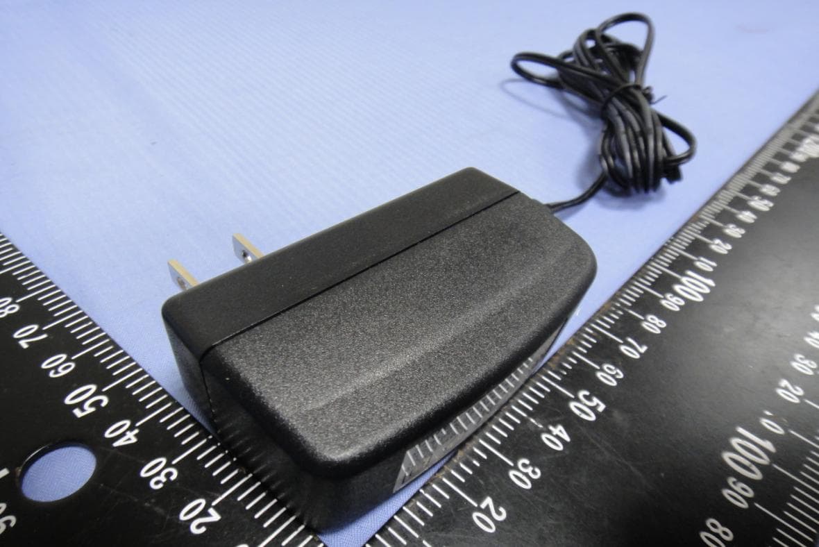
SPORTON International Inc. PAGE NUMBER : 1 OF 6 TEL : 886-2-2696-2468 ISSUED DATE : Oct. 24, 2011 FAX : 886-2-2696-2255 Photographs of EUT SPORTON International Inc. PAGE NUMBER : 2 OF 6 TEL : 886-2-2696-2468 ISSUED DATE : Oct. 24, 2011 FAX : 886-2-2696-2255 SPORTON International Inc. PAGE NUMBER : 3 OF 6 TEL : 886-2-2696-2468 ISSUED DATE : Oct. 24, 2011 FAX : 886-2-2696-2255 SPORTON International Inc. PAGE NUMBER : 4 OF 6 TEL : 886-2-2696-2468 ISSUED DATE : Oct. 24, 2011 FAX : 886-2-2696-2255 SPORTON International Inc. PAGE NUMBER : 5 OF 6 TEL : 886-2-2696-2468 ISSUED DATE : Oct. 24, 2011 FAX : 886-2-2696-2255 SPORTON International Inc. PAGE NUMBER : 6 OF 6 TEL : 886-2-2696-2468 ISSUED DATE : Oct. 24, 2011 FAX : 886-2-2696-2255
ID Label/Location Info
Label siize:40mm*228.5mm
Internal Photos
SPORTON International Inc. PAGE NUMBER : 1 OF 5 TEL : 886-2-2696-2468 ISSUED DATE : Oct. 24, 2011 FAX : 886-2-2696-2255 Photographs of EUT SPORTON International Inc. PAGE NUMBER : 2 OF 5 TEL : 886-2-2696-2468 ISSUED DATE : Oct. 24, 2011 FAX : 886-2-2696-2255 SPORTON International Inc. PAGE NUMBER : 3 OF 5 TEL : 886-2-2696-2468 ISSUED DATE : Oct. 24, 2011 FAX : 886-2-2696-2255 SPORTON International Inc. PAGE NUMBER : 4 OF 5 TEL : 886-2-2696-2468 ISSUED DATE : Oct. 24, 2011 FAX : 886-2-2696-2255 SPORTON International Inc. PAGE NUMBER : 5 OF 5 TEL : 886-2-2696-2468 ISSUED DATE : Oct. 24, 2011 FAX : 886-2-2696-2255
RF Exposure Info
Report No.: FR162501 FCC ID: ODMAP60 Page No. : B1 of B3 Appendix B. Maximum Permissible Exposure Report No.: FR162501 FCC ID: ODMAP60 Page No. : B2 of B3 1. Maximum Permissible Exposure 1.1. Applicable Standard Systems operating under the provisions of this section shall be operated in a manner that ensures that the public is not exposed to radio frequency energy levels in excess limit for maximum permissible exposure. In accordance with 47 CFR FCC Part 2 Subpart J, section 2.1091 this device has been defined as a mobile device whereby a distance of 0.25 m normally can be maintained between the user and the device. (A) Limits for Occupational / Controlled Exposure Frequency Range (MHz) Electric Field Strength (E) (V/m) Magnetic Field Strength (H) (A/m) Power Density (S) (mW/ cm²) Averaging Time |E|²,|H|² or S (minutes) 0.3-3.0 614 1.63 (100)* 6 3.0-30 1842 / f 4.89 / f (900 / f)* 6 30-300 61.4 0.163 1.0 6 300-1500 F/300 6 1500-100,000 5 6 (B) Limits for General Population / Uncontrolled Exposure Frequency Range (MHz) Electric Field Strength (E) (V/m) Magnetic Field Strength (H) (A/m) Power Density (S) (mW/ cm²) Averaging Time |E|²,|H|² or S (minutes) 0.3-1.34 614 1.63 (100)* 30 1.34-30 824/f 2.19/f (180/f)* 30 30-300 27.5 0.073 0.2 30 300-1500 F/1500 30 1500-100,000 1.0 30 Note: f = frequency in MHz ; *Plane-wave equivalent power density 1.2. MPE Calculation Method E (V/m) = d GP30 Power Density: Pd (W/m²) = 377 2 E E = Electric field (V/m) P = Average RF output power (W) G = EUT Antenna numeric gain (numeric) d = Separation distance between radiator and human body (m) The formula can be changed to Pd = 2 377 30 d GP From the EUT RF output power, the minimum mobile separation distance, d=0.2m, as well as the gain of the used antenna, the RF power density can be obtained. Report No.: FR162501 FCC ID: ODMAP60 Page No. : B3 of B3 1.3. Calculated Result and Limit Antenna Type : Dipole Antenna Max Conducted Power for IEEE 802.11b/g: 20.70 dBm Antenna Gain (dBi) Antenna Gain (numeric) Average Output Power (dBm) Average Output Power (mW) Power Density (S) (mW/cm²) Limit of Power Density (S) (mW/cm²) Test Result 2.00 1.5849 20.7000 117.4898 0.037064 1 Complies
Test Report
SPORTON International Inc. No. 52, Hwa Ya 1st Rd., Kwei-Shan Hsiang, TaoYuan Hsien, Taiwan, R.O.C. Ph: 886-3-327-3456 / FAX: 886-3-327-0973 / www.sporton.com.tw Report Format Version: 01 FCC RADIO TEST REPORT Applicant’s company OvisLink Corp. Applicant Address 5F,No.6, Lane 130, Min-Chuan Road, Hsin-Tien Dist., 231 New Taipei City, Taiwan, R.O.C FCC ID ODMAP60 Manufacturer’s company OvisLink Corp. Manufacturer Address 5F,No.6, Lane 130, Min-Chuan Road, Hsin-Tien Dist., 231 New Taipei City, Taiwan, R.O.C Product Name AP60 Brand Name Air Live Model Name AP60, AP60-FCC Test Rule 47 CFR FCC Part 15 Subpart C § 15.247 Test Freq. Range 2400 ~ 2483.5MHz Received Date Sep. 15, 2011 Final Test Date Oct. 20, 2011 Submission Type Original Equipment Multiple Listing Please refer to section 3.7 Statement Test result included in this report is for the IEEE 802.11n and IEEE 802.11b/g part of the product. The test result in this report refers exclusively to the presented test model / sample. Without written approval of SPORTON International Inc., the test report shall not be reproduced except in full. The measurements and test results shown in this test report were made in accordance with the procedures and found in compliance with the limit given in ANSI C63.10-2009 and 47 CFR FCC Part 15 Subpart C. The test equipment used to perform the test is calibrated and traceable to NML/ROC. Report No.: FR162501 Report Format Version: 01 Page No. : iof ii FCC ID: ODMAP60 Issued Date : Oct. 31, 2011 Table of Contents 1. CERTIFICATE OF COMPLIANCE ......................................................................................................................... 1 2. SUMMARY OF THE TEST RESULT .......................................................................................................................... 2 3. GENERAL INFORMATION .................................................................................................................................. 3 3.1. Product Details....................................................................................................................................................................................3 3.2. Accessories .........................................................................................................................................................................................5 3.3. Table for Filed Antenna.......................................................................................................................................................................5 3.4. Table for Carrier Frequencies .............................................................................................................................................................5 3.5. Table for Test Modes ...........................................................................................................................................................................6 3.6. Table for Testing Locations..................................................................................................................................................................6 3.7. Table for Multiple Listing......................................................................................................................................................................7 3.8. Table for Supporting Units ...................................................................................................................................................................7 3.9. Table for Parameters of Test Software Setting .....................................................................................................................................8 3.10. Test Configurations .............................................................................................................................................................................9 4. TEST RESULT ................................................................................................................................................... 11 4.1. AC Power Line Conducted Emissions Measurement.........................................................................................................................11 4.2. Peak Output Power Measurement ....................................................................................................................................................15 4.3. Average Output Power Measurement ..............................................................................................................................................18 4.4. Power Spectral Density Measurement ..............................................................................................................................................21 4.5. 6dB Spectrum Bandwidth Measurement ..........................................................................................................................................26 4.6. Radiated Emissions Measurement ....................................................................................................................................................31 4.7. Band Edge Emissions Measurement .................................................................................................................................................49 4.8. Antenna Requirements .....................................................................................................................................................................58 5. LIST OF MEASURING EQUIPMENTS ................................................................................................................... 59 6. TEST LOCATION.............................................................................................................................................. 61 7. TAF CERTIFICATE OF ACCREDITATION .....................................................…
Text truncated - open the document above for the full version.
Test Setup Photos
Report No.: FR162501 FCC ID: ODMAP60 Page No. : 1 of 6 Appendix A. Test Photos Report No.: FR162501 FCC ID: ODMAP60 Page No. : 2 of 6 1. Photographs of Conducted Emissions Test Configuration FRONT VIEW REAR VIEW Report No.: FR162501 FCC ID: ODMAP60 Page No. : 3 of 6 SIDE VIEW Report No.: FR162501 FCC ID: ODMAP60 Page No. : 4 of 6 2. Photographs of Radiated Emissions Test Configuration Test Configuration: 9kHz ~30MHz FRONT VIEW REAR VIEW Report No.: FR162501 FCC ID: ODMAP60 Page No. : 5 of 6 Test Configuration: 30MHz~1GHz FRONT VIEW REAR VIEW Report No.: FR162501 FCC ID: ODMAP60 Page No. : 6 of 6 Test Configuration: Above 1GHz FRONT VIEW REAR VIEW
Contact Information
Applicant
Sammy Chiu(Product Manager)
Test Firm
Sporton International Inc.Alex Chen
Technical Specifications
| # | Rule Parts | Frequency Range | Power Output |
|---|---|---|---|
| 2 | 15C | 2.42 GHz - 2.45 GHz | 405.00 mW |
Other Applications from OvisLink Corp.
ODMAC1200R
Jun 04, 20151200Mbps 802.11AC AP Router
Equipment Class
DTS - Digital Transmission System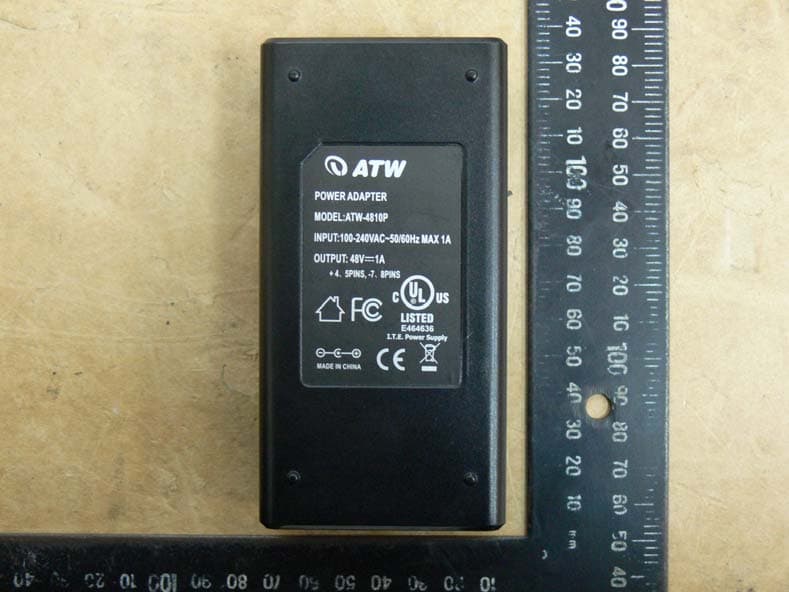
ODMAIRMAX5X
Apr 18, 20155G High Throughput Outdoor CPE with PoE Pass through
Equipment Class
NII - Unlicensed National Information Infrastructure TX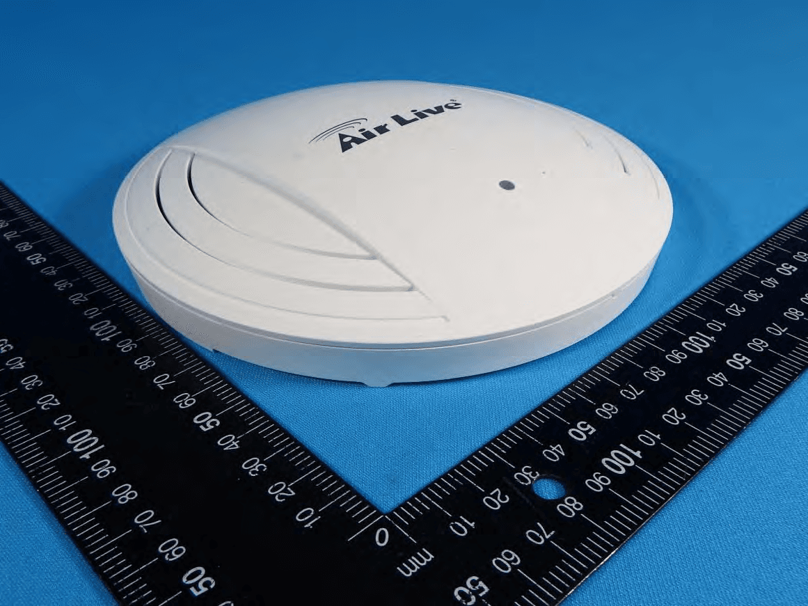
ODMACTOP
Apr 15, 201511 AC Wide Range Ceiling Mount PoE Access Point
Equipment Class
NII - Unlicensed National Information Infrastructure TX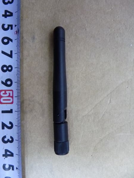
ODMCW720
Mar 19, 2013720P Wireless 150Mbps IPCAM
Equipment Class
DTS - Digital Transmission System
ODMNPOWER
Jan 10, 2013Hi-Power Wireless-N PoE AP Router
Equipment Class
DTS - Digital Transmission System