ODMWMU-6500FSAirLive Wireless Mini PCI Adapter
OvisLink Corp.
Click to zoom
Application Details
- Equipment Class
- DTS - Digital Transmission System
- Date of Grant
- Nov 08, 2007
- Application Purpose
- Original Equipment
- Date of Application
- Nov 08, 2007
- Equipment Note
- AirLive Wireless Mini PCI Adapter
- Frequency Range
- 2412.00000000 - 2462.00000000
- Company
- OvisLink Corp.
- Country
- Taiwan
Documents & Files
Document Text
Text extracted from the exhibit documents filed with the FCC. Open a document above to read the original.
Users Manual
11B/G WMU-6500FS-MPCI AirLive Wireless Mini PCI Adapter User’s Manual - 1 - FCC Information This device complies with Part 15 of the FCC Rules. Operation is subject to the following two conditions: 1. This device may not cause harmful interference. 2. This device must accept any interference received; including interference that may cause undesired operation. Federal Communications Commission (FCC) Statement. This Equipment has been tested and found to comply with the limits for a Class B digital device, pursuant to Part 15 of the FCC rules. These limits are designed to provide reasonable protection against harmful interference in a residential installation. This equipment generates uses and can radiate radio frequency energy and if not installed and used in accordance with the instructions, may cause harmful interference to radio communications. However, there is no guarantee that interference will not occur in a particular installation. If this equipment does cause harmful interference to radio or television reception, which can be determined by turning the equipment off and on, the user is encouraged to try to correct the interference by one or more of the following measures: - Reorient or relocate the receiving antenna. - Increase the separation between the equipment and receiver. - Connect the equipment into an outlet on a circuit different from that to which the receiver is connected. - Consult the dealer or an experienced radio/TV technician for help. FCC RF Radiation Exposure Statement: 1. This Transmitter must not be co-located or operating in conjunction with any other antenna or transmitter. - 2 - Chapter 1 Install Driver for Windows Series This section describes the installation of the 11b/g Wireless Mini PCI Adapter driver for the Windows98/ME/2000 and Windows XP operating systems. 1-1 Set up 11b/g Wireless Mini PCI Adapter for Windows Series Step 1: After inserting the Wireless Mini PCI Adapter into the Mini PCI port on notebook or desktop, the Windows will auto-detect the Wireless Mini PCI Adapter and a “Found New Hardware Wizard” window will show up. Select “Cancel” to install the driver from CD-Rom. - 3 - Step 2: Insert the Product CD-ROM into the CD-ROM drive. Select “Setup.exe” to install Driver and Utility. Step 3: After installing the driver, you can check if your device is active in the device management - 4 - Chapter 2 Configure Wireless Mini PCI Adapter This chapter will show you how to configure your Wireless Mini PCI Adapter by using utility in the Product CD Package under Windows series Operation System 2-1 Install Utility 1. After finishing the install process, you can execute the utility as follows 2. You will see the utility icon after you executing program “Wireless Utility” if your Wireless Mini PCI Adapter is alive 3. If your operation system belong to Windows XP and have update to SP1, click the right button on the icon. You will see the frame below. If you want to configure your Wireless Mini PCI Adapter with “Wireless Zero Configure” supported by XP, you should choose “Use Zero - 5 - Configuration as Configuration utility”. - 6 - 2-2 Configure Wireless Mini PCI Adapter with Zero Configure After installing Wireless Mini PCI Adapter, the Windows XP will display a “Wireless Network Connection ” message. Click on the message and the “Automatic Wireless Network Configuration” will then appear automatically and allow users to connect to an available Wireless infrastructure network (Access Point), shown as follows. You may click the “Advanced” button to make advanced configuration for the Wireless LAN Card, shown as below. In order to reconfigure you Wireless connection, you can deal as follow procedure 1. Click left button on the network icon as bellow. Choose one suitable server - 7 - 2. Click Properties to continue 3. Click Wireless Networks to reconfigure the Wireless network connection. 4. If you need a key (WEP) to connect the Wireless network, you should keyin the key that supported by the Wireless network router or access point - 8 - - 9 - Chapter 3 Configure Wireless Mini PCI Adapter with “ Wireless Utility” for Windows 98/ME/2000/XP Click the utility icon, and you will see the application interface as step 2. 3-1 Site Survey Page 1. The means of item z SSID : Name of AP z BSSID : Mac Address of AP z Signal : Signal strength of AP z Channel : AP used channel z Encryption : what encrypted mechanism does AP used, the encrypted mechanism contain four ways , WEP, AES, TKIP, NOT USE z Authentication : What authentication mechanism does AP used. - 10 - z Network Type : What Network Type does the AP belong to. 2. The connected AP z the system will choose the suitable AP when you start up RaConfig in the first time z if you want to connect with another AP, double click mouse’s left button in the SSID of AP. z indicate connect successful. 3. if the connect is success, it will show the SSID of the connected AP 4. rescan and upgrade all the AP’s information in time 5. connect with selected AP 6. Save the selected AP’s information to Profile 3-1-1 Add/Edit Profile System Configuration: as figure bellow - 11 - 1. Profile Name: Different AP can be set up into different Profile Name 2. SSID: The drop-down menu can select which AP is detected by system 3. Power Save Mode: can selectCAMConstantly Awake Mode or Power Saving Mode mode. Selecting the” CAM when AC Power” means the power saving mode can automatically switch into CAM, if the computer uses the AC power, not using the batteries instead. Selecting the “Power Save Mode” can only work under the infrastructure mode. 4. Network Type: Can select “Infrastructure” or “802.11 Ad Hoc” mode. When set up to “Infrastructure” mode, the “Power Saving” mode will be enabled, but the “11b Preamble Type” will not; When set up to “802.11 Ad Hoc” mode, the “Power Saving Mode” will not be enabled, but “11b Preamble” will, and the channel selection in the session 7 will show up as well. 5. TX Power: Transmit power, the amount of p…
Text truncated - open the document above for the full version.
Cover Letter(s)
Transmitter Modular Approval Letter Date: October 29, 2007 Federal Communications Commission Re: Application Modular Approval Certification for FCC ID: ODMWMU-6500FS Gentlemen: The following attestation addresses the eight requirements to support Modular approval as required by the FCC Public Notice DA 00-1407” Part 15 Unlicensed Modular Transmitter Approval” 1 The modular transmitter has its own RF shielding.(Refer to “Internal Photograph Exhibit”) 2 The modular transmitter has buffered modulation/data inputs. All inputs to the modules are buffered through the radio circuitry. (Refer to “Block Diagram and Schematics Exhibit”) 3 The modular transmitter has its own power supply regulator.(Refer to “Block Diagram and Schematics Exhibit ”and Bill of Materials Exhibit”) 4 The modular transmitter has an antenna that complies with section 15.203 of the FCC rules. It has a UFL type of connector at the transmitter end and is Printed to the antenna (depending on OEM configuration). Also the antenna will be internal in the OEM host equipment and inaccessible to the user.(Refer to “Operational Description Exhibit” and “Antenna Specification Exhibit”) 5 The modular transmitter was tested outside of a host desktop computer using a PCI extender card. The PCI extender card allows the transmitter to be placed outside of the chassis of the host desktop computer.(Refer to “Test Configuration”in Compliance Certificaiton Services Inc. test report and to “External Photograph Exhibit”) 6 The modular transmitter will be labeled with it own FCC ID. Also, the OEM host computer manufacturer will be informed to display a label referring to the enclosed module. The exterior habel will read as follows: “Contains Transmitter Module FCC ID: ODMWMU-6500FS” or “Contains TX FCCID: ODMWMU-6500FS” (Refer to “Label Information Exhibit”) 7 The modular transmitter is manufactured so that the user cannot influence the operation of the transmitter that will operate outside of the scope of the regulations.(Refer to“User’s Guide Exhibit) 8 The modular transmitter meets the MPE calculations of 47 CFR 1.1307(b)(1) (Refer to “RF Exposure Exhibit”.)
External Photos
Compliance Certification Services Inc. Report No.:70928404-RP1 External Photo ( Model : AirLive WMU-6500FS-MPCI)
ID Label/Location Info
Company : OvisLink Corp. Model : AirLive WMU-6500FS-MPCI Product : Wireless Mini PCI Adapter Label Here Wireless Mini PCI Adapter Model No: AirLive WMU-6500FS-MPCI FCC ID:ODMWMU-6500FS This device complies with part 15 of the FCC Rules. Operation is subject to the following two conditions: [1] this device may not cause harmful interference and [2] this device must accept any interference received, including interference that may cause undesired operation. S/N: Made in Taiwan
Internal Photos
Compliance Certification Services Inc. Report No.:70928404-RP1 Compliance Certification Services Inc. Report No.:70928404-RP1
RF Exposure Info
Compliance Certification Services Inc. Report No: 70928404-RP1 FCC ID: ODMWMU-6500FS Date of Issue: October 2, 2007 7.5 RADIO FREQUENCY EXPOSURE LIMIT Systems operating under the provisions of this section shall be operated in a manner that ensures that the public is not exposed to radio frequency energy levels in excess of the Commission's guidelines. See §15.247(i) and §1.1307(b)(1) of this chapter. EUT Specification EUT AirLive Wireless Mini PCI Adapter Frequency band (Operating) WLAN: 2.412GHz ~ 2.462GHz WLAN: 5.18GHz ~ 5.32GHz / 5.50GHz ~ 5.70GHz WLAN: 5.745GHz ~ 5.825GHz Others Device category Portable (<20cm separation) Mobile (>20cm separation) Others Exposure classification Occupational/Controlled exposure (S = 5mW/cm2) General Population/Uncontrolled exposure (S=1mW/cm2) Antenna diversity Single antenna Multiple antennas Tx diversity Rx diversity Tx/Rx diversity Max. output power 18.60dBm (72.4436mW) Antenna gain (Max) 5 dBi (Numeric gain: 3.162278) Evaluation applied MPE Evaluation SAR Evaluation Remark: 1. The maximum output power is 18.60(72.4436mW) at 2412MHz (with 3.162278 numeric antenna gain.) 2. DTS device is not subject to routine RF evaluation; MPE estimate is used to justify the compliance. 3. For mobile or fixed location transmitters, no SAR consideration applied. The minimum separation generally be used is at least 20 cm, even if the calculations indicate that the MPE distance would be lesser. TEST RESULTS No non-compliance noted. Compliance Certification Services Inc. Report No: 70928404-RP1 FCC ID: ODMWMU-6500FS Date of Issue: October 2, 2007 Calculation Given d GP E ×× = 30 & 3770 2 E S= Where E = Field Strength in Volts / meter P = Power in Watts G=Numeric antenna gain d=Distance in meters S=Power Density in milliwatts / square centimeter Combining equations and re-arranging the terms to express the distance as a function of the remaining variables yields: S GP d × ×× = 3770 30 Changing to units of mW and cm, using: P (mW) = P (W) / 1000 and d (cm) =100 * d (m) Yields S GP S GP d × ×= × ×× ×=282.0 3770 )1000/(30 100 Where d = distance in cm P = Power in mW G = Numeric antenna gain S = Power Density in mW / cm^2 Substituting the logarithmic form of power and gain using: P (mW) = 10 ^ (P (dBm) / 10) and G (numeric) = 10 ^ (G (dBi) / 10) Yields 20 10 282.0 20 )(GP d + ×= Equation 1 Where d = MPE safe distance in cm P = Power in dBm G = Antenna Gain in dBi S = Power Density Limit in mW / cm^2 Compliance Certification Services Inc. Report No: 70928404-RP1 FCC ID: ODMWMU-6500FS Date of Issue: October 2, 2007 Maximum Permissible Exposure (2.4 GHz Band) EUT output power = 72.4436mW Antenna Gain = 3.162278(Numeric gain) S = 1.0 mW / cm^2 from 1.1310 Table 1 Substituting these parameters into the above Equation 1: Æ MPE Safe Distance =4.309826cm (For mobile or fixed location transmitters, the minimum separation distance is 20 cm, even if calculations indicate that the MPE distance would be less.)
Test Report
Compliance Certification Services Inc. Report No: 70928404-RP1 FCC ID: ODMWMU-6500FS Date of Issue: October 2, 2007 NOTE: This report shall not be reproduced except in full, without the written approval of Compliance Certification Services Inc. This document may be altered or revised by Compliance Certification Services Inc. personnel only, and shall be noted in the revision section of the document. Total Page: 73 Page 1 FCC 47 CFR PART 15 SUBPART C TEST REPORT For AirLive Wireless Mini PCI Adapter Model Number: AirLive WMU-6500FS-MPCI Brand Name: Air Live Issued to OvisLink Corp. 5F, No.6 Lane 130, Min-Chuan Road ,Hsin-Tien City Taipei , Taiwan , R.O.C Issued by Compliance Certification Services Inc. Ta i n a n L a b . No. 8, Jiu Cheng Ling, Jiaokeng Village,Sinhua Township, Tainan Hsien 712, Taiwan R.O.C. TEL: 886-6-580-2201 FAX: 886-6-580-2202 Compliance Certification Services Inc. Report No: 70928404-RP1 FCC ID: ODMWMU-6500FS Date of Issue: October 2, 2007 Page 2 TABLE OF CONTENTS 1 TEST RESULT CERTIFICATION....................................................................................................3 2 EUT DESCRIPTION ...........................................................................................................................4 3 TEST METHODOLOGY ....................................................................................................................5 3.1 EUT CONFIGURATION.......................................................................................................................5 3.2 EUT EXERCISE..................................................................................................................................5 3.3 GENERAL TEST PROCEDURES............................................................................................................5 3.4 FCC PART 15.205 RESTRICTED BANDS OF OPERATIONS .......................................................6 3.5 DESCRIPTION OF TEST MODES...........................................................................................................7 4 INSTRUMENT CALIBRATION........................................................................................................7 5 FACILITIES AND ACCREDITATIONS ..........................................................................................8 5.1 FACILITIES.........................................................................................................................................8 5.2 EQUIPMENT.......................................................................................................................................8 5.3 LABORATORY ACCREDITATIONS AND LISTING.................................................................................8 5.4 TABLE OF ACCREDITATIONS AND LISTINGS......................................................................................9 6 SETUP OF EQUIPMENT UNDER TEST .......................................................................................10 6.1 SETUP CONFIGURATION OF EUT......................................................................................................10 6.2 SUPPORT EQUIPMENT ...............................................................................................................10 7 FCC PART 15.247 REQUIREMENTS.............................................................................................11 7.1 6DB BANDWIDTH ........................................................................................................................11 7.2 PEAK POWER...................................................................................................................................17 7.3 BAND EDGES MEASUREMENT ................................................................................................23 7.4 PEAK POWER SPECTRAL DENSITY...................................................................................................33 7.5 RADIO FREQUENCY EXPOSURE........................................................................................................39 7.6 SPURIOUS EMISSIONS ...............................................................................................................42 7.7 POWER LINE CONDUCTED EMISSIONS.............................................................................................69 8 APPENDIX 1 PHOTOGRAPHS OF TEST SETUP .......................................................................72 Compliance Certification Services Inc. Report No: 70928404-RP1 FCC ID: ODMWMU-6500FS Date of Issue: October 2, 2007 Page 3 1 TEST RESULT CERTIFICATION Applicant :OvisLink Corp. Address :5F, No.6 Lane 130, Min-Chuan Road ,Hsin-Tien City Taipei , Tai wa n , R. O. C Equipment Under Test :AirLive Wireless Mini PCI Adapters Model Number :AirLive WMU-6500FS-MPCI Brand Name :Air Live Date of Test :April 21, 2006 ~ April 28, 2006 APPLICABLE STANDARDS STANDARD TEST RESULT FCC 47 CFR Part 15 Subpart C No non-compliance noted We hereby certify that: The above equipment was tested by Compliance Certification Services Inc. The test data, data evaluation, test procedures, and equipment configurations shown in this report were made in accordance with the procedures given in ANSI C63.4 and the energy emitted by the sample EUT tested as described in this report is in compliance with the requirements of FCC Rules Part 15.207, 15.209, 15.247. The test results of this report relate only to the tested sample EUT identified in this report. This report is transferred from 60410407-RP1. Approved by: Reviewed by: October 5, 2007 October 5, 2007 Jeter Wu Eric Yang Section Manager Engineer Compliance Certification Services Inc. Compliance Certification Services Inc. Compliance Certification Services Inc. Report No: 70928404-RP1 FCC ID: ODMWMU-6500FS Date of Issue: October 2, 2007 Page 4 2 EUT DESCRIPTION Product AirLive Wireless Mini PCI Adapter Model Number AirLive WMU-6500FS-MPCI Brand Name Air Live Model Discrepancy N/A Power…
Text truncated - open the document above for the full version.
Test Setup Photos
Compliance Certification Services Inc. Report No: 70928404-RP1 FCC ID: ODMWMU-6500FS Date of Issue: October 2, 2007 8 APPENDIX 1 PHOTOGRAPHS OF TEST SETUP Radiated Emission Set up Photos Compliance Certification Services Inc. Report No: 70928404-RP1 FCC ID: ODMWMU-6500FS Date of Issue: October 2, 2007 Conducted Emission Set Up Photos
Contact Information
Applicant
Sammy Chiu(Product Manager)
Test Firm
Compliance Certification Services Inc.Alex Chiu
Technical Specifications
| # | Rule Parts | Frequency Range | Power Output |
|---|---|---|---|
| 1 | 15C | 2.41 GHz - 2.46 GHz | 72.40 mW |
Other Applications from OvisLink Corp.
ODMAC1200R
Jun 04, 20151200Mbps 802.11AC AP Router
Equipment Class
DTS - Digital Transmission System
ODMAIRMAX5X
Apr 18, 20155G High Throughput Outdoor CPE with PoE Pass through
Equipment Class
NII - Unlicensed National Information Infrastructure TX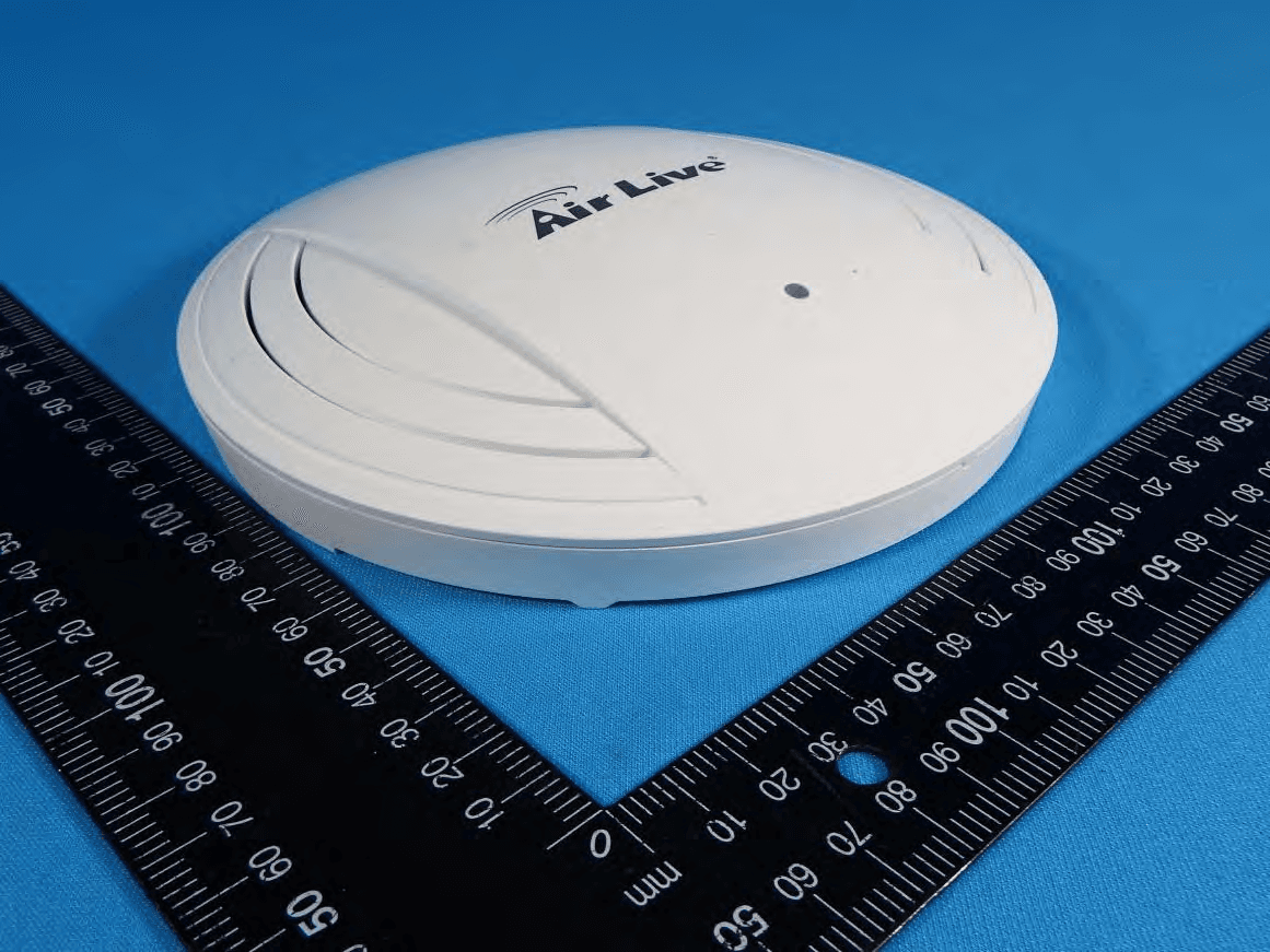
ODMACTOP
Apr 15, 201511 AC Wide Range Ceiling Mount PoE Access Point
Equipment Class
NII - Unlicensed National Information Infrastructure TX
ODMCW720
Mar 19, 2013720P Wireless 150Mbps IPCAM
Equipment Class
DTS - Digital Transmission System
ODMNPOWER
Jan 10, 2013Hi-Power Wireless-N PoE AP Router
Equipment Class
DTS - Digital Transmission System