ODMWS12G802.11G Internet Access Server
OvisLink Corp.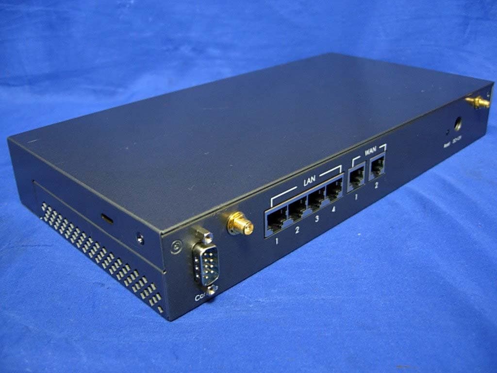
Click to zoom
Application Details
- Equipment Class
- DTS - Digital Transmission System
- Date of Grant
- Oct 23, 2007
- Application Purpose
- Original Equipment
- Date of Application
- Oct 05, 2007
- Equipment Note
- 802.11G Internet Access Server
- Frequency Range
- 2412.00000000 - 2462.00000000
- Company
- OvisLink Corp.
- Country
- Taiwan
Documents & Files
Document Text
Text extracted from the exhibit documents filed with the FCC. Open a document above to read the original.
Users Manual
WIAS-1200G 802.11G Internet Access Server User’s Manual User’s Manual Federal Communication Commission Interference Statement This equipment has been tested and found to comply with the limits for a Class B digital device, pursuant to Part 15 of FCC Rules. These limits are designed to provide reasonable protection against harmful interference in a residential installation. This equipment generates, uses, and can radiate radio frequency energy and, if not installed and used in accordance with the instructions, may cause harmful interference to radio communications. However, there is no guarantee that interference will not occur in a particular installation. If this equipment does cause harmful interference to radio or television reception, which can be determined by turning the equipment off and on, the user is encouraged to try to correct the interference by one or more of the following measures: 1. Reorient or relocate the receiving antenna. 2. Increase the separation between the equipment and receiver. 3. Connect the equipment into an outlet on a circuit different from that to which the receiver is connected. 4. Consult the dealer or an experienced radio technician for help. FCC Caution This device and its antenna must not be co-located or operating in conjunction with any other antenna or transmitter. This device complies with Part 15 of the FCC Rules. Operation is subject to the following two conditions: (1) this device may not cause harmful interference, and (2) this device must accept any interference received, including interference that may cause undesired operation. Any changes or modifications not expressly approved by the party responsible for compliance could void the authority to operate equipment. Federal Communication Commission (FCC) Radiation Exposure Statement This equipment must be installed and operated in accordance with providednstructions and the antenna(s) used for this transmitter must be installed toprovide a separation distance of at least 20 cm from all persons and mustnot be co-located or operating in conjunction with any other antenna or transmitter. End-users and installers must be provide with antenna exposure compliance. R&TTE Compliance Statement This equipment complies with all the requirements of DIRECTIVE 1999/5/EC OF THE EUROPEAN PARLIAMENT AND THE COUNCIL of March 9, 1999 on radio equipment and telecommunication terminal Equipment and the mutual recognition of their conformity (R&TTE) The R&TTE Directive repeals and replaces in the directive 98/13/EEC (Telecommunications Terminal Equipment and Satellite Earth Station Equipment) As of April 8, 2000. Safety This equipment is designed with the utmost care for the safety of those who install and use it. However, special attention must be paid to the dangers of electric shock and static electricity when working with electrical equipment. All guidelines of this and of the computer manufacture must therefore be allowed at all times to ensure the safe use of the equipment. EU Countries Intended for Use The ETSI version of this device is intended for home and office use in Austria, Belgium, Denmark, Finland, France, Germany, Greece, Ireland, Italy, Luxembourg, the Netherlands, Portugal, Spain, Sweden, and the United Kingdom. The ETSI version of this device is also authorized for use in EFTA member states: Iceland, Liechtenstein, Norway, and Switzerland. COPYRIGHT Copyright ©2007/2008 by this company. All rights reserved. No part of this publication may be reproduced, transmitted, transcribed, stored in a retrieval system, or translated into any language or computer language, in any form or by any means, electronic, mechanical, magnetic, optical, chemical, manual or otherwise, without the prior written permission of this company This company makes no representations or warranties, either expressed or implied, with respect to the contents hereof and specifically disclaims any warranties, merchantability or fitness for any particular purpose. Any software described in this manual is sold or licensed "as is". Should the programs prove defective following their purchase, the buyer (and not this company, its distributor, or its dealer) assumes the entire cost of all necessary servicing, repair, and any incidental or consequential damages resulting from any defect in the software. Further, this company reserves the right to revise this publication and to make changes from time to time in the contents thereof without obligation to notify any person of such revision or changes. ClauseDescription ■ EN 300 328 V1.6.1Electromagnetic compatibility and Radio spectrum Matters (ERM); (2004-11)Wideband transmission equipment operating in the 2.4GHz ISM band And using spread spectrum modulation techniques; Part 1:technical Characteristics and test conditions Part2:Harmonized EN covering Essential requirements under article 3.2 of the R&TTE Directive ■ EN 301 489-1 V1.6.1Electromagnetic compatibility and Radio spectrum Matters (ERM); (2005-09)Electromagnetic compatibility(EMC) standard for radio equipment and ■ EN 301 489-17 V1.6.1Services; Part 17:Specific conditions for wideband data and (2005-09)HIPERLAN equipment ■ EN 60950-1:2006Safety for information technology equipment including electrical business equipment ■ CE marking Signature: Name :Albert Yeh Position/ Title : Vice President Date: 2007/6/7 (Stamp) Declaration of Conformity We, Manufacturer/Importer OvisLink Corp. 5F., NO.6, Lane 130, Min-Chuan Rd., Hsin-Tien City, Taipei County, Taiwan Declare that the product 802.11G Internet Access Server WIAS-1200G is in conformity with In accordance with 89/336 EEC-EMC Directive and 1999/5 EC-R & TTE Directive Manufacturer/Importer WIAS-1200G CE Declaration Statement CountryDeclarationCountryDeclaration cs Česky [Czech] OvisLink Corp. tímto prohlašuje, že tento WIAS- 1200G je ve shodě se základními požadavky a dalšími příslušnými ustanoveními směrnice 1999/5/ES. lt Lietuvių [Lithuanian] Šiuo OvisLink Corp. deklaruoja, kad šis…
Text truncated - open the document above for the full version.
Users Manual
AirLive WIAS-1200G User’s Guide 83 y Port and IP Redirect This function allows the administrator to set 40 sets of the IP addresses at most for redirection purpose. When the user attempts to connect to a destination IP address listed here, the connection packet will be converted and redirected to the corresponding destination. Please enter the “IP Address” and “Port” of Destination, and the “IP Address” and “Port” of Translated to Destination. According to the different services provided, choose the “TCP” protocol or the “UDP” protocol. These settings will become effective immediately after clicking Apply. AirLive WIAS-1200G User’s Guide 84 4.3.2 Privilege List There are two parts, Privilege IP Address List and Privilege MAC Address List, can be set. y Privilege IP Address List If there are some workstations belonging to the managed server that need to access the network without authentication, enter the IP addresses of these workstations in this list. The “Remark” blank is not necessary but is useful to keep track. AirLive WIAS-1200G allows 100 privilege IP addresses at most. These settings will become effective immediately after clicking Apply Note: Permitting specific IP addresses to have network access rights without going through standard authentication process at the Public LAN (LAN1/LAN2) may cause security problems. y Privilege MAC Address List In addition to the IP address, the MAC address of the workstations that need to access the network without authentication can also be set in this list. AirLive WIAS-1200G allows 100 privilege MAC addresses at most. When manually creating the list, enter the MAC address (the format is xx:xx:xx:xx:xx:xx) as well as the remark (not necessary). These settings will become effective immediately after clicking Apply. AirLive WIAS-1200G User’s Guide 85 Note: Permitting specific MAC addresses to have network access rights without going through standard authentication process at the Public LAN (LAN1/LAN2) may cause security problems.. AirLive WIAS-1200G User’s Guide 86 4.3.3 Monitor IP List AirLive WIAS-1200G will send out a packet periodically to monitor the connection status of the IP addresses on the list. If the monitored IP address does not respond, the system will send an e-mail to notify the administrator that such destination is not reachable. After entering the related information, click Apply and these settings will become effective immediately. Click Monitor to check the current status of all the monitored IP. The system provides 40 IP addresses for the “Monitor IP List”. y Send From: The e-mail address of the administrator in charge of the monitoring. This will show up as the sender’s e-mail. y Send To: The e-mail address of the person whom the monitoring result is for. This will be the receiver’s e-mail. y Interval: The time interval to send the e-mail report. y SMTP Server: The IP address of the SMTP server. y Auth Method: The system provides four authentication methods, Plain, Login, CRAM-MD5 and NTLMv1, or “None” to use none of the above. Depending on which authentication method selected, enter the Account Name, Password and Domain. y Send Test Email: To test the settings correct or not. y Monitor IP Address: The IP addresses under monitoring. AirLive WIAS-1200G User’s Guide 87 4.3.4 Walled Garden List This function provides some free services to the users to access websites listed here before login and authentication. Up to 20 addresses or domain names of the websites can be defined in this list. Users without the network access right can still have a chance to experience the actual network service free of charge. Please enter the website IP Address or Domain Name in the list and these settings will become effective immediately after clicking Apply. AirLive WIAS-1200G User’s Guide 88 4.3.5 Proxy Server Properties AirLive WIAS-1200G supports Internal Proxy Server and External Proxy Server functions. Please select an Access Gateway and then perform the necessary configurations. y External Proxy Server: Under the AirLive WIAS-1200G security management, the system will match the External Proxy Server list to the end-users’ proxy setting. If there isn’t a match, then the end-users will no be able to reach the login page and thus unable to access the network. If there is a match, the end-users will be directed to the system first for authentication. After a successful authentication, the end-users will be redirected back to the desired proxy servers depending on various situations. y Internal Proxy Server: AirLive WIAS-1200G has a built-in proxy server. If this function is enabled, the end users will be forced to treat AirLive WIAS-1200G as the proxy server regardless of the end-users’ original proxy settings. Note: For more details about how to set up the proxy servers, please refer to Appendix E and Appendix F. AirLive WIAS-1200G User’s Guide 89 4.3.6 Dynamic DNS AirLive WIAS-1200G provides a convenient DNS function to translate the IP address of WAN port to a domain name that helps the administrator memorize and connect to WAN port. If the DHCP is activated at WAN port, this function will also update the newest IP address regularly to the DNS server. These settings will become effective immediately after clicking Apply. y DDNS: Enabling or disabling of this function. y Provider: Select the DNS provider. y Host name: The IP address/domain name of the WAN port. y Username/E-mail: The register ID (username or e-mail) for the DNS provider. y Password/Key: The register password for the DNS provider. AirLive WIAS-1200G User’s Guide 90 4.4 Utilities This section provides four utilities to customize and maintain the system including Change Password, Backup/Restore Setting, Firmware Upgrade and Restart. AirLive WIAS-1200G User’s Guide 91 4.4.1 Network Utilities The system provides three network diagnostic tools like PING, Trace Route, and ARP Table, for the administrator to diagnose the network status. y PING: Enter the desired IP address such …
Text truncated - open the document above for the full version.
Cover Letter(s)
RX 802.11a 5320MHz
Cover Letter(s)
American Telecommunications Certification Body Inc. 6731 Whittier Ave, McLean, VA 22101 October 7, 2007 RE: ATCB005505 FCC ID: ODMWS12G I have a few comments on this application. Depending on your responses, kindly understand there may be additional comments. 1. For 802.11b/g with 22~23dBm output power, the radiated carrier level should not be such low as shown page 34 to 41. Please explain. ~~~~~~~~~~~~~~~~~~~~~~~~~~~~~~ ~ George Chen ~ mailto:[email protected] ~ Taiwan Mobile: +886 930600123 ~ SKYPE: georgeshirley ~~~~~~~~~~~~~~~~~~~~~~~~~~~~~~ The items indicated above must be submitted before processing can continue on the above referenced application. Failure to provide the requested information may result in application termination. Correspondence should be considered part of the permanent submission and may be viewed from the Internet after a Grant of Equipment Authorization is issued. Please do not respond to this correspondence using the email reply button. In order for your response to be processed expeditiously, you must submit your documents through the AmericanTCB.com website. Also, please note that partial responses increase processing time and should not be submitted. Any questions about the content of this correspondence should be directed to the sender.
Cover Letter(s)
American Telecommunications Certification Body Inc. 6731 Whittier Ave, McLean, VA 22101 October 12, 2007 RE: ATCB005505 FCC ID: ODMWS12G I have a few comments on this application. Depending on your responses, kindly understand there may be additional comments. 1. The peak level of radiated bandedge emission at 2390MHz frequency point (page 35, 39) and at 2483.5MHz (page 37,40,41) is higher than average limit. It is necessary to provide the average measurement (RBW=1MHz, VBW=10Hz) for these frequency points to show their average emission level is lower than average limit. Please provide us an updated test report. ~~~~~~~~~~~~~~~~~~~~~~~~~~~~~~ ~ George Chen ~ mailto:[email protected] ~ Taiwan Mobile: +886 930600123 ~ SKYPE: georgeshirley ~~~~~~~~~~~~~~~~~~~~~~~~~~~~~~ The items indicated above must be submitted before processing can continue on the above referenced application. Failure to provide the requested information may result in application termination. Correspondence should be considered part of the permanent submission and may be viewed from the Internet after a Grant of Equipment Authorization is issued. Please do not respond to this correspondence using the email reply button. In order for your response to be processed expeditiously, you must submit your documents through the AmericanTCB.com website. Also, please note that partial responses increase processing time and should not be submitted. Any questions about the content of this correspondence should be directed to the sender.
External Photos
Report No.: 077322R-RFUSP05V01 Page : 1 of 12 Version:1.0 Attachment 2 : EUT Detailed Photographs (1) EUT Photo (2) EUT Photo
ID Label/Location Info
OvisLink Corp. FCC ID.: ODMWS12G 5F, No.6, Lane 130, Min-Chuan Rd., Hsin-Tien City, Taipei County 231, Taiwan FCC ID Label The FCC ID Label will be placed on the equipment as shown in the photograph below.
Internal Photos
Report No.: 077322R-RFUSP05V01 Page : 2 of 12 Version:1.0 (3) EUT Photo (4) EUT Photo Report No.: 077322R-RFUSP05V01 Page : 3 of 12 Version:1.0 (5) EUT Photo (6) EUT Photo Report No.:077322R-RFUSP05V01 Page : 4 of 12 Version:1.0 (7) EUT Photo (8) EUT Photo Report No.: 077322R-RFUSP05V01 Page : 5 of 12 Version:1.0 (9) EUT Photo (10) EUT Photo Report No.: 077322R-RFUSP05V01 Page : 6 of 12 Version:1.0 (11) EUT Photo (12) EUT Photo Report No.: 077322R-RFUSP05V01 Page : 7 of 12 Version:1.0 (13) EUT Photo (14) EUT Photo Report No.: 077322R-RFUSP05V01 Page : 8 of 12 Version:1.0 (15) EUT Photo (16) EUT Photo Report No.: 077322R-RFUSP05V01 Page : 9 of 12 Version:1.0 (17) EUT Photo (18) EUT Photo Report No.: 077322R-RFUSP05V01 Page : 10 of 12 Version:1.0 (19) EUT Photo (20) EUT Photo Report No.: 077322R-RFUSP05V01 Page : 11 of 12 Version:1.0 (21) EUT Photo (22) EUT Photo Report No.: 077322R-RFUSP05V01 Page : 12 of 12 Version:1.0 (23) EUT Photo
RF Exposure Info
Report No. 077322R-RFUSP05V01 Page: 1 of 3 Version: 1.0 RF Exposure Evaluation declaration Product Name : 802.11G Internet Access Server Model No. : WIAS-1200G FCC ID : ODMWS12G Applicant : OvisLink Corp. Address : 5F, No.6, Lane 130, Min-Chuan Rd., Hsin-Tien City, Taipei County 231, Taiwan Date of Receipt : June 06, 2007 Date of Declaration : Oct. 03, 2007 Report No. : 077322R-RFUSP05V01 The declaration results relate only to the samples calculated. The declaration shall not be reproduced except in full without the written approval of QuieTek Corporation. This report must not be used to claim product endorsement by NVLAP any agency of the U.S. Government Report No. 077322R-RFUSP05V01 Page: 2 of 3 Version: 1.0 1. RF Exposure Evaluation 1.1. Limits According to FCC 1.1310: The criteria listed in the following table shall be used to evaluate the environment impact of human exposure to radio frequency (RF) radiation as specified in 1.1307(b) LIMITS FOR MAXIMUM PERMISSIBLE EXPOSURE (MPE) Frequency Range (MHz) Electric Field Strength (V/m) Magnetic Field Strength (A/m) Power Density (mW/cm 2 ) Average Time (Minutes) (A) Limits for Occupational/ Control Exposures 300-1500 -- -- F/300 6 1500-100,000 -- -- 5 6 (B) Limits for General Population/ Uncontrolled Exposures 300-1500 -- -- F/1500 6 1500-100,000 -- -- 1 30 F= Frequency in MHz Friis Formula Friis transmission formula: Pd = (Pout*G)/(4*pi*r 2 ) Where Pd = power density in mW/cm 2 Pout = output power to antenna in mW G = gain of antenna in linear scale Pi = 3.1416 R = distance between observation point and center of the radiator in cm Pd id the limit of MPE, 1 mW/cm 2 . If we know the maximum gain of the antenna and the total power input to the antenna, through the calculation, we will know the distance r where the MPE limit is reached. 1.2. Test Procedure Software provided by client enabled the EUT to transmit and receive data at lowest, middle and highest channel individually. The temperature and related humidity: 18°Cand 78% RH. Report No. 077322R-RFUSP05V01 Page: 3 of 3 Version: 1.0 1.3. Test Result of RF Exposure Evaluation Product : 802.11G Internet Access Server Test Item : RF Exposure Evaluation Test Site : No.3 OATS Antenna Gain Antenna Gain: The maximum Gain measured in fully anechoic chamber is 4.5 dBi in logarithm scale. 802.11b Output Power Into Antenna & RF Exposure Evaluation Distance (4.5 dBi): Channel Frequency (MHz) Output Power to Antenna (mW) Power Density at R = 20 cm (mW/cm2) 1 2412.00 206.0630 0.1155 6 2437.00 214.7830 0.1204 11 2462.00 202.3019 0.1134 802.11g Output Power Into Antenna & RF Exposure Evaluation Distance (4.5 dBi): Channel Frequency (MHz) Output Power to Antenna (mW) Power Density at R = 20 cm (mW/cm2) 1 2412.00 166.3413 0.0933 6 2437.00 179.8871 0.1009 11 2462.00 174.9847 0.0981 The distance r (4 th column) calculated from the Fries transmission formula is far shorter than 20 cm separation requirement.
Test Report
Report No. 077322R-RFUSP05V01 Page: 1 of 58 Version:1.0 Test Report Product Name 802.11G Internet Access Server Model No. WIAS-1200G FCC ID ODMWS12G Applicant OvisLink Corp. Address 5F, No.6, Lane 130, Min-Chuan Rd., Hsin-Tien City, Taipei County 231, Taiwan Date of Receipt June 06, 2007 Issued Date Oct. 03, 2007 Report No. 077322R-RFUSP05V01 The test results relate only to the samples tested. The test report shall not be reproduced except in full without the written approval of QuieTek Corporation. This report must not be used to claim product endorsement by NVLAP any agency of the U.S. Government Report No. 077322R-RFUSP05V01 Page: 2 of 58 Version:1.0 Test Report Certification Issued Date: Oct. 03, 2007 Report No.: 077322R-RFUSP05V01 Test results relate only to the samples tested. The test report shall not be reproduced except in full without the written approval of QuieTek Corporation. This report must not be used to claim product endorsement by NVLAP any agency of the U.S. Government Product Name 802.11G Internet Access Server Applicant OvisLink Corp. Address 5F, No.6, Lane 130, Min-Chuan Rd., Hsin-Tien City, Taipei County 231, Taiwan Manufacturer OvisLink Corp. Model No. WIAS-1200G Rated Voltage AC 120V/60Hz Working Voltage AC 120V/60Hz Trade Name Air Live Applicable Standard FCC CFR Title 47 Part 15 Subpart C: 2006 ANSI C63.4: 2003 Test Result Complied Documented By : ( Engineering Adm. Specialist / Rita Huang ) Tested By : (Engineer /Molin Huang) Approved By : ( Deputy Manager / Vincent Lin) Accredited by NIST (NVLAP) NVLAP Lab Code: 200533-0 0914 Report No. 077322R-RFUSP05V01 Page: 3 of 58 Version:1.0 TABLE OF CONTENTS Description Page 1. GENERAL INFORMATION .....................................................................................................5 1.1. EUT Description............................................................................................................................5 1.2. Operational Description ................................................................................................................6 1.3. Tested System Datails....................................................................................................................7 1.4. Configuration of Test System ........................................................................................................7 1.5. EUT Exercise Software .................................................................................................................7 1.6. Test Facility ...................................................................................................................................8 2. Conducted Emission....................................................................................................................9 2.1. Test Equipment..............................................................................................................................9 2.2. Test Setup ......................................................................................................................................9 2.3. Limits ............................................................................................................................................9 2.4. Test Procedure .............................................................................................................................10 2.5. Uncertainty ..................................................................................................................................10 2.6. Test Result of Conducted Emission.............................................................................................11 3. Peak Power Output ...................................................................................................................15 3.1. Test Equipment............................................................................................................................15 3.2. Test Setup ....................................................................................................................................15 3.3. Limits ..........................................................................................................................................15 3.4. Uncertainty ..................................................................................................................................15 3.5. Test Result of Peak Power Output...............................................................................................16 4. Radiated Emission .....................................................................................................................20 4.1. Test Equipment............................................................................................................................20 4.2. Test Setup ....................................................................................................................................21 4.3. Limits ..........................................................................................................................................22 4.4. Test Procedure .............................................................................................................................23 4.5. Uncertainty ..................................................................................................................................23 4.6. Test Result of Radiated Emission................................................................................................24 5. Band Edge ..................................................................................................................................32 Report No. 077322R-RFUSP05V01 Page: 4 of 58 Version:1.0 5.1. Test Equipment............................................................................................................................32 5.2. Test Setup ................................................…
Text truncated - open the document above for the full version.
Test Setup Photos
Report No.: 077322R-RFUSP05V01 Page : 1 of 3 Version:1.0 Attachment 1: EUT Test Setup Photographs Front View of Conducted Test Back View of Conducted Test Report No.: 077322R-RFUSP05V01 Page : 2 of 3 Version:1.0 Front View of Radiated Test Back View of Radiated Test Report No.: 077322R-RFUSP05V01 Page : 3 of 3 Version:1.0 Front View of Radiated Test (Horn) Back View of Radiated Test (Horn)
Contact Information
Applicant
Sammy Chiu(Product Manager)
Test Firm
quietek.comJames Chang
Technical Specifications
| # | Rule Parts | Frequency Range | Power Output |
|---|---|---|---|
| 1 | 15C | 2.41 GHz - 2.46 GHz | 214.70 mW |
Other Applications from OvisLink Corp.
ODMAC1200R
Jun 04, 20151200Mbps 802.11AC AP Router
Equipment Class
DTS - Digital Transmission System
ODMAIRMAX5X
Apr 18, 20155G High Throughput Outdoor CPE with PoE Pass through
Equipment Class
NII - Unlicensed National Information Infrastructure TX
ODMACTOP
Apr 15, 201511 AC Wide Range Ceiling Mount PoE Access Point
Equipment Class
NII - Unlicensed National Information Infrastructure TX
ODMCW720
Mar 19, 2013720P Wireless 150Mbps IPCAM
Equipment Class
DTS - Digital Transmission System
ODMNPOWER
Jan 10, 2013Hi-Power Wireless-N PoE AP Router
Equipment Class
DTS - Digital Transmission System