OE5PP2ProxiPen RFID Tag Reader
G4S Technology Limited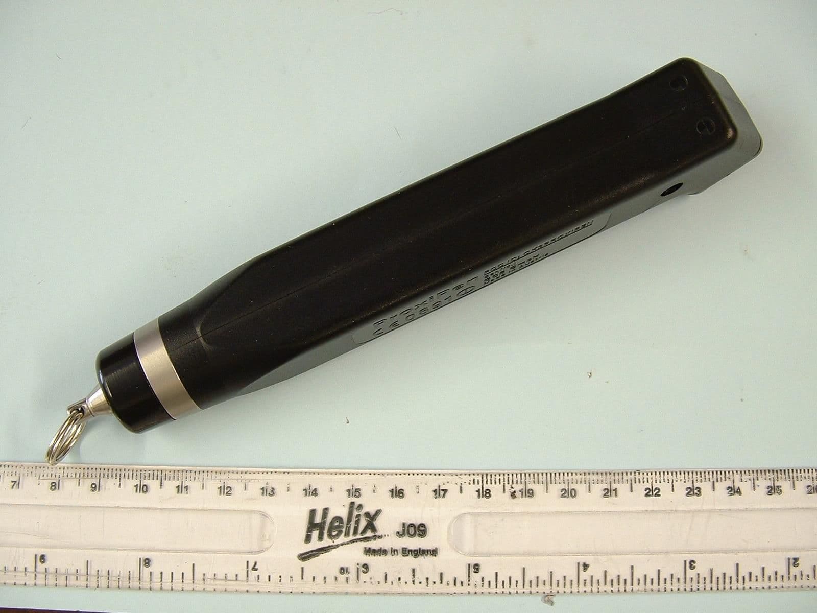
Click to zoom
Application Details
- Equipment Class
- DCD - Part 15 Low Power Transmitter Below 1705 kHz
- Date of Grant
- Aug 15, 2006
- Application Purpose
- Original Equipment
- Date of Application
- Aug 06, 2006
- Equipment Note
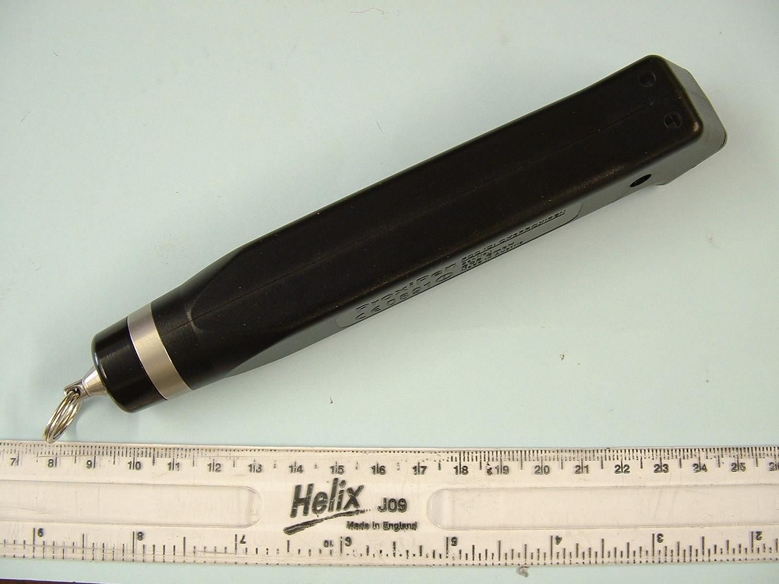
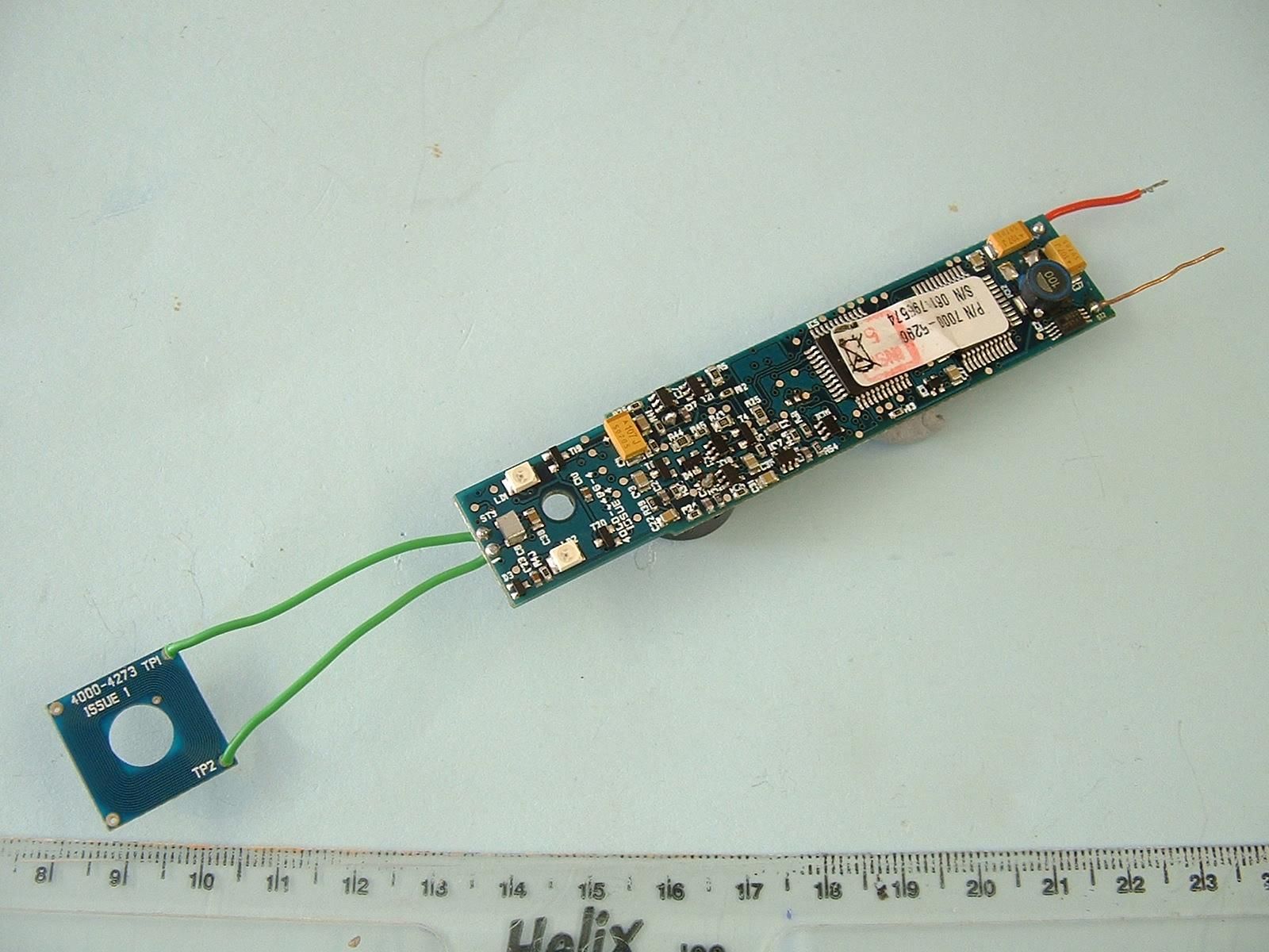
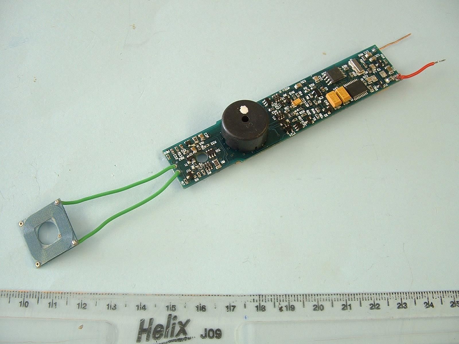
- ProxiPen RFID Tag Reader
- Frequency Range
- 0.12595000 - 0.12595000
- Company
- G4S Technology Limited
- Country
- United Kingdom
Documents & Files
Document Text
Text extracted from the exhibit documents filed with the FCC. Open a document above to read the original.
Users Manual
9600-0258 Starter Set Inst. ProxiPen (Int.) - 07 2006 ProxiPenStarter Kit 120/230Quick Set-up Manual Instructions d‘installation rapide Instrucciones iniciales Schnellstartanleitung U.S.: www.gcsus.comU.K.: : www.gcs-control-systems.co.uk GCS provides your solution for trust with verification ProxiPen Starter KitProxiPen System [6] [2] [5] [4] [3] [1] A B C D E F DeutschSchnellstartanleitung1. Schalten Sie den PC [1] aus und schließen Sie die DTU [2] mit dem beiliegenden Kabel [3] an eine freie serielle Schnittstelle des PCs [1] an (Abb. A). 2. Schließen Sie das beiliegende Netzgerät [4] an die DTU [2] an und stecken Sie das Netzgerät [4] in eine Steckdose [5]. Das Lämpchen „ Power “ander PenDTU [2] leuchtet (Abb. B). 3. Öffnen Sie das Batteriefach am ProxiPen [6] durch Drehen gegen den Uhrzeigersinn und entfernen Sie die Batterieisolierung (Abb. C). 4. Schließen Sie das Batteriefach wieder und legen Sie den ProxiPen [6] auf die PenDTU [2]. Das Lämpchen „ Pen “aufder PenDTU [2] leuchtet (Abb. D). 5. Schalten Sie den PC [1] ein. Das Lämpchen „ Online “ auf der PenDTU [2] leuchtet (Abb. E). 6. Installieren Sie die beiliegende Software. Nähere Informationen hierzu finden Sie in der CD Box. 7. Setzen Sie mit der Software die Zeitzone der PenDtu. Nähere Informationen hierzu entnehmen Sie bitte der Online-Hilfe der Software. 8. Setzen Sie mittels der Software das Datum und die Zeit des ProxiPen. Nähere Informationen hierzu entnehmen Sie bitte der Online-Hilfe der Software. Lesen mit dem ProxiPenDen ProxiPen dem TAG nähern (Abb. F).Gültige Lesungen werden akustisch und durch Aufblitzen der Lämpchen quittiert. English Quick Start Up Instructions1. Turn off your PC [1] and connect the DTU [2] with the PC-Cable included in the kit [3] toafreeserialportonthe PC [1] (Ill. A). 2. Connect the Power Supply included in the kit [4] to the DTU [2] and plug the Power Supply [4] into an outlet [5]. The light „ Power “onthe PenDTU [2] is now illuminated (Ill. B). 3. Open the battery cap on the ProxiPen [6] by turning it counter-clockwise and re- move the battery insulation tab (Ill. C). 4. Put the battery into the ProxiPen and screw the battery cap back on. Place the ProxiPen [6] on the PenDTU [2]. The light „ Pen “onthe PenDTU [2] is now illu- minated (Ill. D). 5. Turn on your PC [1] . The light „ Online “onthe PenDTU [2] is now illuminated (Ill. E). 6. Install the Software in your PC from the CD-ROM included in the kit. For more in- formation about installing the software see the instructions in the CD case. 7. Set the time zone in the PenDTU using the software now installed on your PC. For more information about setting the time zone, see the Online-Help included inthe Software. 8. Set the date and time in the ProxiPen using the Software now installed on your PC. For more information about setting the date and time, see the Online-Help includedin the Software. Reading RF Tags with the ProxiPenMove the ProxiPen to an RF-TAG. (Ill. F)Good readings are confirmed by an acoustic signal and a flash of the LEDs on theProxiPen. FrançaisInstructions d’installation rapide1. Eteignez le PC [1] et connectez la DTU [2] avec le câble [3] fourni à un port série libre du PC [1] (fig. A). 2. Connectez le transformateur [4] fourni à la DTU [2] et branchez-le à une prise de courant [5].La diode „ Power “surla PenDTU [2] s’allume (fig. B). 3. Dévissez en sens inverse des aiguilles d’une montre la fermeture de la batterie du ProxiPen [6] et retirez la pellicule d’isolation de la batterie (fig. C). 4. Refermezlafermeturedelabatterieetposezle ProxiPen [6] sur la PenDTU [2]. La diode „ Pen “surla PenDTU [2] s’allume (fig. D). 5. Allumez le PC [1] . La diode „ Online “surla PenDTU [2] s’allume (fig. E). 6. Installez le logiciel fourni. Vous trouvez plus d’informations dans le boîtier du CD. 7. RéglezlefuseauhorairedelaPenDtuaveclelogiciel. Vous trouvez plus d’informations dans l’aide en ligne du logiciel. 8. Réglez la date et l’heure du ProxiPen avec le logiciel. Vous trouvez plus d’informations dans l’aide en ligne du logiciel. Lire avec le ProxiPenApprochez le ProxiPen du TAG (fig. F).Des lectures valables sont confirmées par un signal acoustique et optique(les diodes s’allument). Español Instrucciones iniciales para un correcto uso: 1. Apague su PC [1] y conecte el DTU [2] mediante el Cable-PC incluido en el kit [3] a cualquier puerto serie libre del PC [1] (Ill. A). 2. Conecte el Alimentador incluido en el kit [4] al DTU [2] y enchufe el Alimentador [4] alacorriente [5]. La luz „ Power “del PenDTU [2 ] debe aparecer encendida (Ill. B). 3. Abra la tapa de la batería del ProxiPen [6] girándo en sentido contrario a las agujas del reloj. Quite la batería y retire la tapa protectora que se encuentra en el inter- ior (Ill. C). 4. Ponga de nuevo la batería en el ProxiPen y apriete la tapa. Coloque el ProxiPen [6] sobre el PenDTU [2]. La luz „ Pen “del PenDTU [2] debe encenderse (Ill. D). 5. Encienda su PC [1] .Laluz„ Online “del PenDTU [2] debe iluminarse (Ill. E). 6. Instale en su PC el software suministrado en el CD-ROM incluido en el kit. Para más información sobre la instalación de este software siga las instrucciones incluidasen la caja del CD. 7. Configure la zona horaria del PenDTU mediante el software que ha instalado en su PC. Para más información sobre cómo configurar la zona horaria puede utilizar elmenú de ayuda del propio Software. 8. Configure la fecha y hora del ProxiPen mediante el software que ha instalado en su PC. Para más información sobre cómo configurar la fecha y hora puede utilizar elmenú de ayuda del propio Software. Lectura de etiquetas RF-TAG con el ProxiPenAcerque el ProxiPen a cualquier etiqueta RF-TAG (Ill. F).Si la lectura es correcta recibirá una confirmación mediante una señal acústica y un par-padeo de los LEDs del ProxiPen.
Test Report
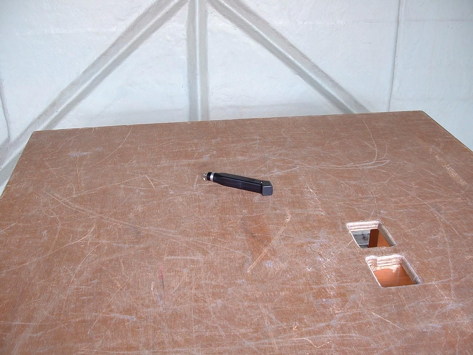
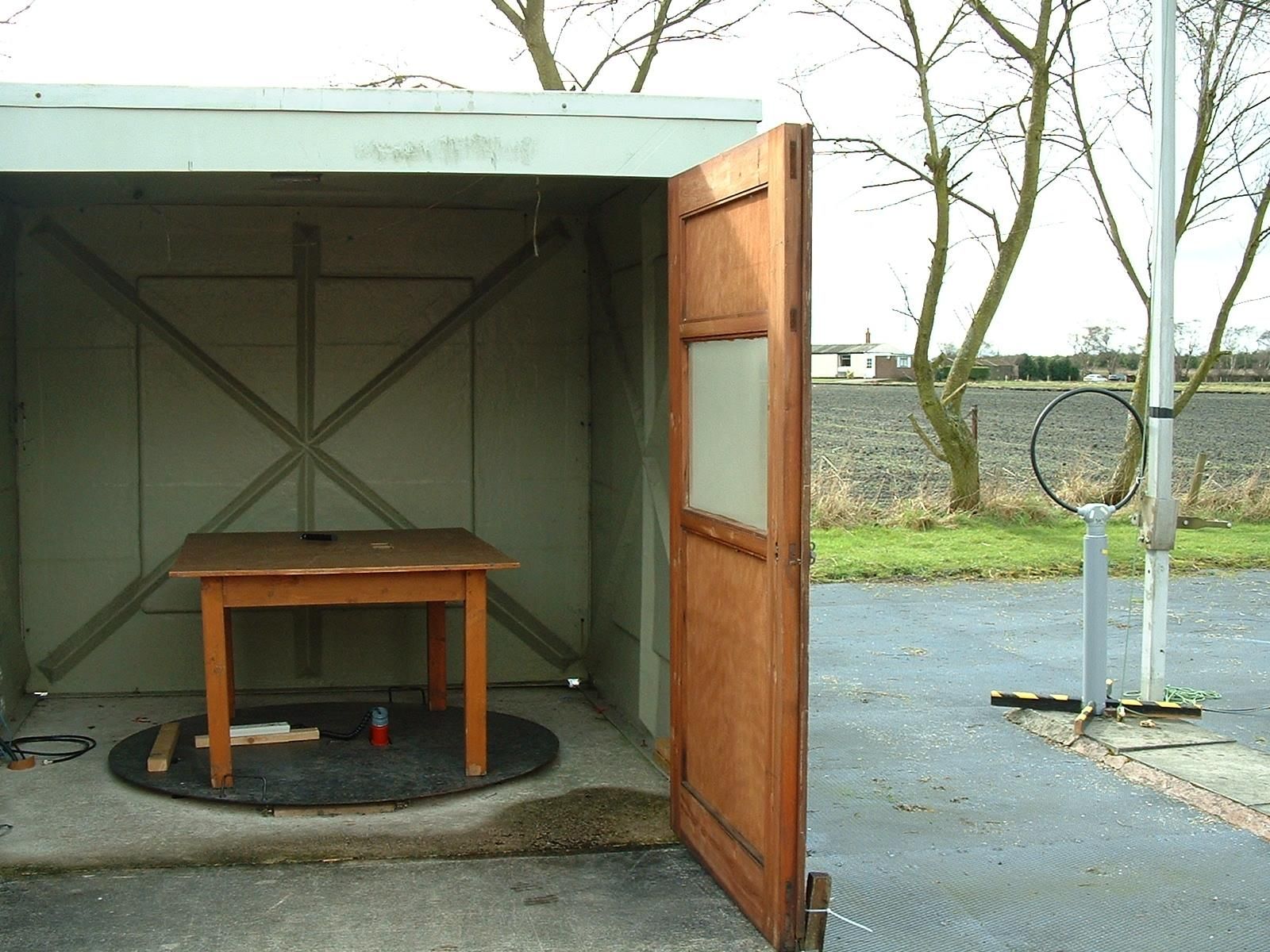
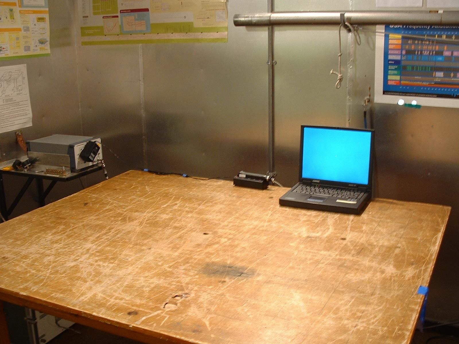
TRL COMPLIANCE LTD M OSS VIEW NIPE LANE UP HOLLAND WEST LANCASHIRE WN8 9PY UNITED KINGDOM T ELEPHONE +44 (0)1695 556666 FAX +44 (0)1695 557077 E-MAIL [email protected] www.trlcompliance.com 0728 TEST REPORT NO: RU1231/6922 COPY NO: 2 ISSUE NO: 1 FCC ID: OE5PP2 REPORT ON THE CERTIFICATION TESTING OF A GROUP 4 TECHNOLOGY Ltd PROXIPEN WITH RESPECT TO THE FCC RULES CFR 47, PART 15.209 INTENTIONAL RADIATOR SPECIFICATION TEST DATE: 27 th – 29 th March 2006 TESTED BY: D WINSTANLEY APPROVED BY: P GREEN EMC PRODUCT MANAGER DATE: 3 rd August 2006 Distribution: Copy Nos: 1. Group 4 Technology Limited 2. TCB: TRL Compliance Limited 3. TRL Compliance Limited THIS DOCUMENT MAY BE REPRODUCED ONLY IN ITS ENTIRETY AND WITHOUT CHANGE TRL RF335U iss01B RU1231/6922 Page 2 of 29 CONTENTS PAGE CERTIFICATE OF CONFORMITY & COMPLIANCE 3 APPLICANT’S SUMMARY 4 EQUIPMENT TEST CONDITIONS 5 TESTS REQUIRED 5 TEST RESULTS 6-11 ANNEX PHOTOGRAPHS A PHOTOGRAPH No. 1: Test setup PHOTOGRAPH No. 2: Transmitter Top View PHOTOGRAPH No. 3: Transmitter Side View PHOTOGRAPH No. 4: Transmitter PCB Top Side PHOTOGRAPH No. 5: Transmitter PCB Bottom Side APPLICANT’S SUBMISSION OF DOCUMENTATION LIST B BAND OCCUPANCY PLOT C CONDUCTED EMISSIONS D 30MHz – 1000MHz SCAN PLOT E TEST EQUIPMENT CALIBRATION F MEASUREMENT UNCERTAINTY G Notes: 1. Component failure during test YES NO [ ] [X] 2. If Yes, details of failure: 3. The facilities used for the testing of the product contain in this report are FCC Listed. 4. The contents of the attached applicants declarations and other supplied information are not covered by the scope of this laboratory’s UKAS or FCC accreditations’ and is provided in good faith. TRL RF335U iss01B RU1231/6922 Page 3 of 29 CERTIFICATE OF CONFORMITY & COMPLIANCE FCC IDENTITY: OE5PP2 PURPOSE OF TEST: Certification TEST SPECIFICATION: FCC RULES CFR 47, Part 15.209 TEST RESULT: Compliant to Specification EQUIPMENT UNDER TEST: Proxipen EQUIPMENT SERIAL No: 001 ITU: EMISSION CODE: 52k8K1N EQUIPMENT TYPE: Inductive Tag Reader PRODUCT USE: Time and Location Verification CARRIER EMISSION: 0.019μV/m @ 300m ANTENNA TYPE: Integral ALTERNATIVE ANTENNA: Not applicable FREQUENCY OF OPERATION: 125.95 kHz CHANNEL SPACING: Not applicable NUMBER OF CHANNELS: 1 FREQUENCY GENERATION: SAW Resonator [X] Crystal [ ] Synthesiser [ ] MODULATION METHOD: Amplitude [ ] Digital [X] Angle [ ] POWER SOURCE(s): 1.2Vdc TEST DATE(s): 27 th – 29 th March 2006 ORDER No(s): PUR71540 APPLICANT: Group 4 Technology Limited ADDRESS: Building 2 Challenge House International Drive Tewkesbury Gloucestershire GL20 8UQ TESTED BY: D WINSTANLEY APPROVED BY: P GREEN EMC PRODUCT MANAGER TRL RF335U iss01B RU1231/6922 Page 4 of 29 APPLICANT’S SUMMARY EQUIPMENT UNDER TEST (EUT): Proxipen EQUIPMENT TYPE: Inductive Tag Reader SERIAL NUMBER OF EUT: 001 PURPOSE OF TEST: Certification TEST SPECIFICATION(s): FCC RULES CFR 47, Part 15.209 TEST RESULT: COMPLIANT Yes No [X] [ ] APPLICANT’S CATEGORY: MANUFACTURER IMPORTER DISTRIBUTOR TEST HOUSE AGENT [X] [ ] [ ] [ ] [ ] APPLICANT’S ORDER No(s): PUR71540 APPLICANT’S CONTACT PERSON(s): Mr E Porter E-mail address: [email protected] APPLICANT: Group 4 Technology Limited ADDRESS: Building 2 Challenge House International Drive Tewkesbury Gloucestershire GL20 8UQ TEL: +44 (0) 1684 850977 FAX: +44 (0) 1684 277500 MANUFACTURER: Group 4 Technology Limited EUT(s) COUNTRY OF ORIGIN: United Kingdom TEST LABORATORY: TRL Compliance UKAS ACCREDITATION No: 0728 TEST DATE(s): 27 th – 29 th March 2006 TEST REPORT No: RU1231/6922 TRL RF335U iss01B RU1231/6922 Page 5 of 29 EQUIPMENT TEST / EXAMINATIONS REQUIRED 1. TEST/EXAMINATION RULE PART DETECTOR APPLICABILITY Intentional Emission Frequency: 15.209(a) Average Yes Intentional Emission Field Strength: 15.209(a) Average Yes Intentional Emission Band Occupancy: 15.215(c) Peak Yes Intentional Emission ERP (mW): - - No Spurious Emissions – Conducted: 15.207 Quasi Peak Average Yes Spurious Emissions – Radiated <1000MHz: 15.209 Quasi Peak Average Yes Spurious Emissions – Radiated >1000MHz: - - No Maximum Frequency of Search: 15.33 - Yes Antenna Arrangements Integral: 15.203 - Yes Antenna Arrangements External Connector: 15.204 - Yes Restricted Bands 15.205 - Yes Extrapolation Factor 15.31(f) - Yes 2. Product Use: Time and Location Verification 3. Emission Designator: 52k8k1N 4. Duty Cycle: <100% 5. Transmitter bit or pulse rate and level: 19200bps 6. Temperatures: Ambient (Tnom) 13 o C 7. Supply Voltages: Vnom +1.2Vdc Note: Vnom voltages are as stated above unless otherwise shown on the test report page Single channel [X] Two channel [ ] 8. Equipment Category: Multi-channel [ ] Narrowband [ ] Wideband [X] 9. Channel spacing: TRL RF335U iss01B RU1231/6922 Page 6 of 29 TRANSMITTER TESTS TRANSMITTER SPURIOUS EMISSIONS – RADIATED – PART 15.209 Ambient temperature = 13 o C(<1GHz) 3m measurements <30MHz [X] Relative humidity = 48% (<1GHz), 3m measurements <1GHz [X] Conditions = Open Area Test Site (OATS) 300m extrapolated from 3m [X] Supply voltage = +1.2Vdc Channel number = 1 FREQ (MHz) MEAS. Rx. (dBμV) CABLE LOSS (dB) ANT FACT (dB 1/m) FIELD STRENGTH (dBμV/m) EXTRAP FACTOR (dB) FIELD STRENGTH (μV/m) 0.009 MHz - 0.49 MHz No Significant Emissions Detected 0.49 MHz - 1.705 MHzNo Significant Emissions Detected 1.705 MHz - 30 MHz No Significant Emissions Detected 30MHz - 88MHz No Significant Emissions Detected 88MHz - 216MHz No Significant Emissions Detected 216MHz - 960MHz No Significant Emissions Detected 960MHz - 1GHz No Significant Emissions Detected 1GHz - 5GHz No Significant Emissions Detected 0.009 MHz to 0.49 MHz 2400/F(kHz) @ 300m 0.49 MHz to 1.705 MHz 24000/F(kHz) @ 30m 1.705MHz to 30MHz 30μV/m @ 30m 30MHz to 88MHz 100μV/m @ 3m 88MHz to 216MHz 150μV/m @ 3m 216MHz to 960MHz 200μV/m @ 3m 960MHz to 1GHz 500μV/m @ 3m Limits 1GHz to 5GHz 500μV/m @ 3m Notes: 1 Results quoted are extrapolated as indicated. 2 Emissions were searched to: (x) 1000MHz inclusive, as per Part 15.33a. 3 Extrapolation factor 9.5dB …
Text truncated - open the document above for the full version.
Contact Information
Applicant
ANDY WATTS(Mr)
Technical Contact
Group 4 Technology LtdEric Porter
[email protected]+44 1684 850977
New Challenge House · Tewkesbury, Glos · United Kingdom
Test Firm
TRL Compliance LtdJohn Charters
Technical Specifications
| # | Rule Parts | Frequency Range | Power Output |
|---|---|---|---|
| 1 | 15C | 0.12595 MHz - 0.12595 MHz | - |
Other Applications from G4S Technology Limited
OE5S870C
Dec 22, 2025Proximity card reader with keypad for access control systems
Equipment Class
DCD - Part 15 Low Power Transmitter Below 1705 kHz
OE5S884C
Dec 22, 2025Access Control Keypad Reader 884 MKII
Equipment Class
DXX - Part 15 Low Power Communication Device Transmitter
OE5S874C
Dec 19, 2025Smartcard reader with keypad for access control systems 874 MKII
Equipment Class
DXX - Part 15 Low Power Communication Device Transmitter
OE5S884O
Jan 20, 2020S884O Proximity Reader
Equipment Class
DXX - Part 15 Low Power Communication Device Transmitter
OE5S680A
Nov 19, 2013S680 Proximity Card Reader
Equipment Class
DXX - Part 15 Low Power Communication Device Transmitter