OE5S711Model S710/711 Contactless Smart Card Reader
G4S Technology Limited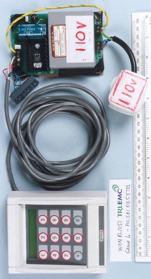
Click to zoom
Application Details
- Equipment Class
- DSR - Part 15 Remote Control/Security Device Transceiver
- Date of Grant
- Jun 20, 2000
- Application Purpose
- Original Equipment
- Date of Application
- May 30, 2000
- Equipment Note
- Model S710/711 Contactless Smart Card Reader
- Frequency Range
- 13.55300000 - 13.56700000
- Company
- G4S Technology Limited
- Country
- United Kingdom
Documents & Files
Document Text
Text extracted from the exhibit documents filed with the FCC. Open a document above to read the original.
Block Diagram
MIFARE PROCESSOR RESET MULTINODE COMMS RRI COMMS KEYPAD CONTROL PROCESSOR POWER SUPPLY 12V d.c. TAMPER RAM EPROM Figure 1:S700 Mifare Reader Block Diagram LCD HGU COMMS MIFARE ANTENNA
Operational Description
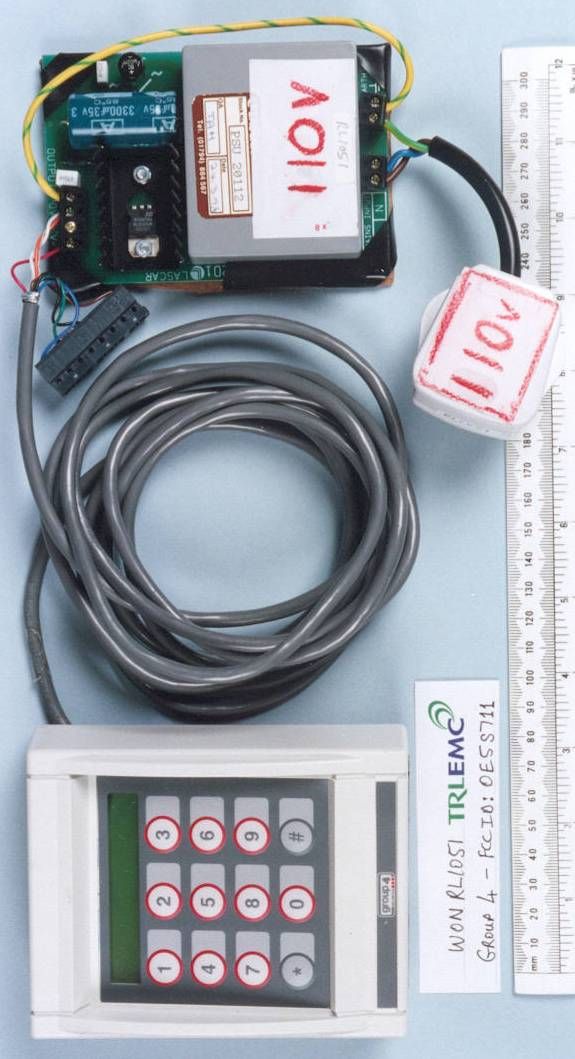
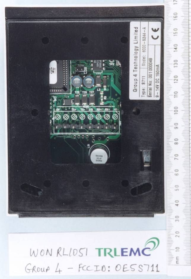
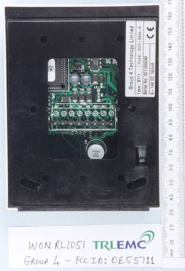
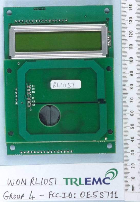
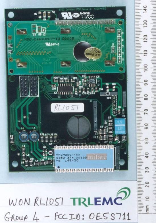
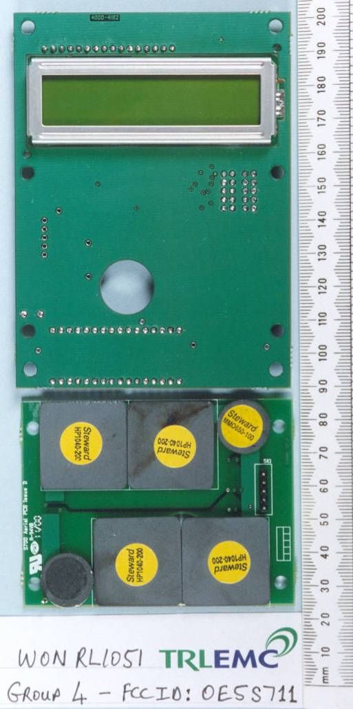
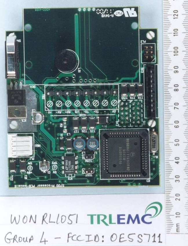
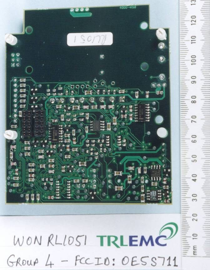
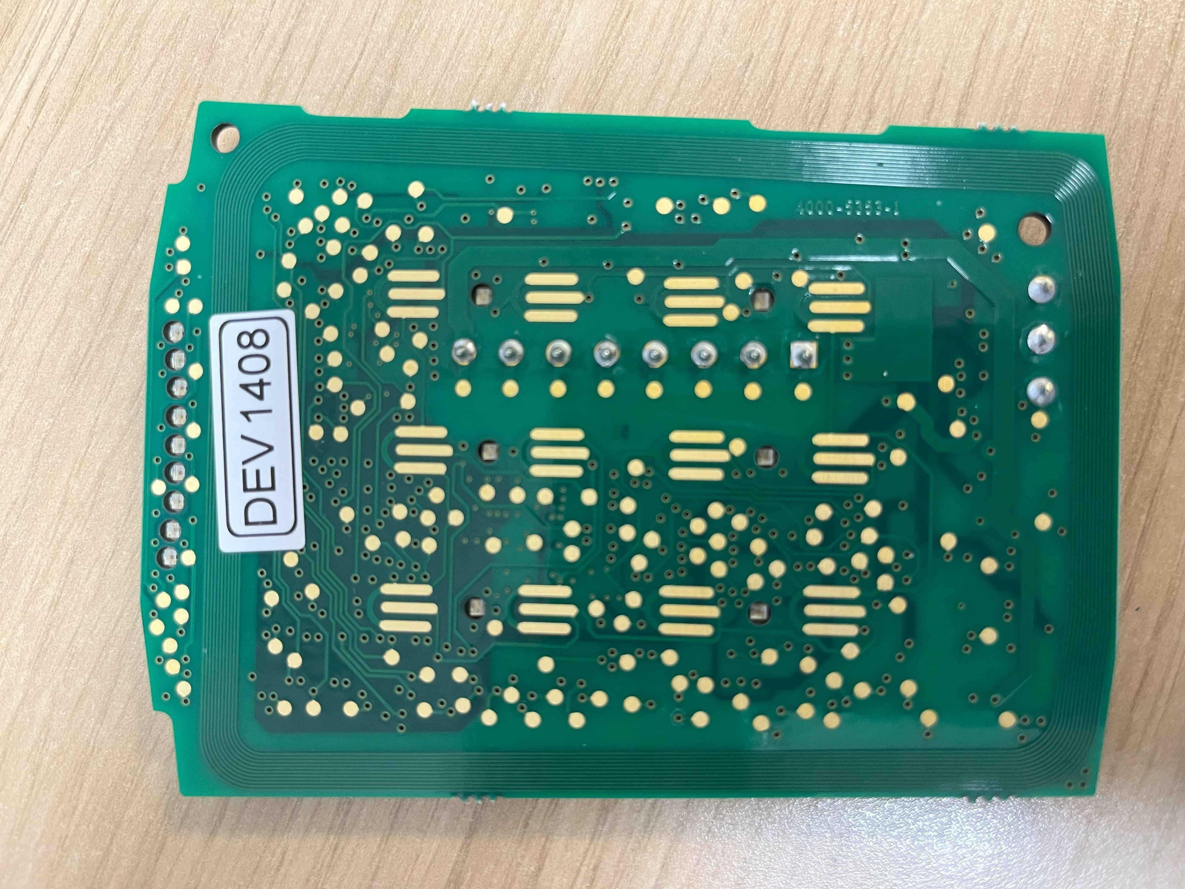
S711 MIFARE PROXIMITY READER WITH KEYPAD 8000-5244 TECHNICAL DESCRIPTION OF OPERATION The S671 Proximity Reader’s intended purpose is to read identification codes programmed into passive mifare cards, accept PINs through a keypad and display a response on a LCD. The maximum read range is about 1”. The unit is connected by cable to a Multinode-2 controller which provides the necessary power and control/interface signals. The circuitry is contained on three PCBs and these are mounted in a plastic enclosure (125mm x 100mm x 45mm or 5” x 4” x 1.5” approx.). The PCB nearest the keypad forms the antenna, with the r.f. circuitry and the LCD control on the middle PCB, while the remainder of the circuitry including the terminal block for power and signals is on the final PCB. The cable from the terminal block exits through the large hole in the back of the unit. A second terminal block is provided to allow connection with a hand geometry unit but the function is not supported in the current reader firmware. The power supply operating range is 9V – 14V d.c. which is used to power the current loop comms to the controller. A 5V regulator powers the remainder of the circuit including the antenna drive. The antenna is a printed coil that emits a 13.56MHz magnetic field. The field ‘powers up’ a passive transponder or tag which is brought into the vicinity of the antenna. The transponder, when powered, operates as a field disturbance device allowing two-way communication to take place between the reader and the card. The field is switched on continuously and modulation of the field is carried out by a dedicated device that is manufactured by Philips for the purpose. The control processor handles the bi-directional communications between the reader and the controller, responding to commands received and passing card data and status information back to the controller. The control processor also carries out housekeeping tasks such as scanning the keypad and monitoring the tamper switch. The unit has a second serial port for use with a remote door control unit. The data to and from this port is processed by the control processor.
Test Report
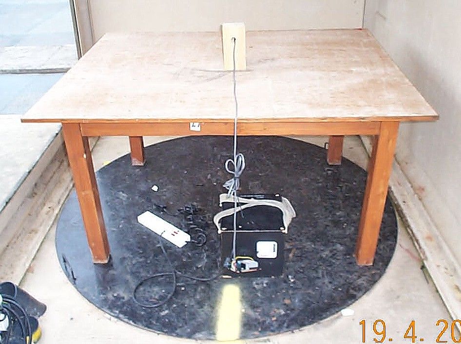
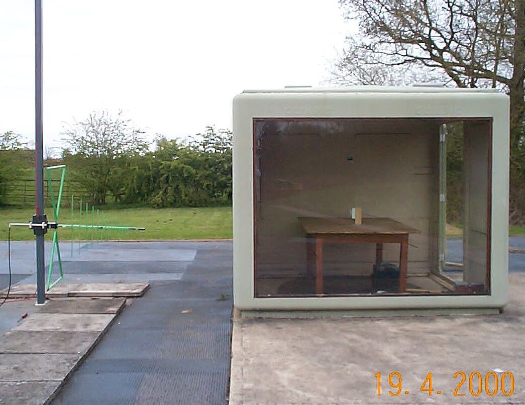
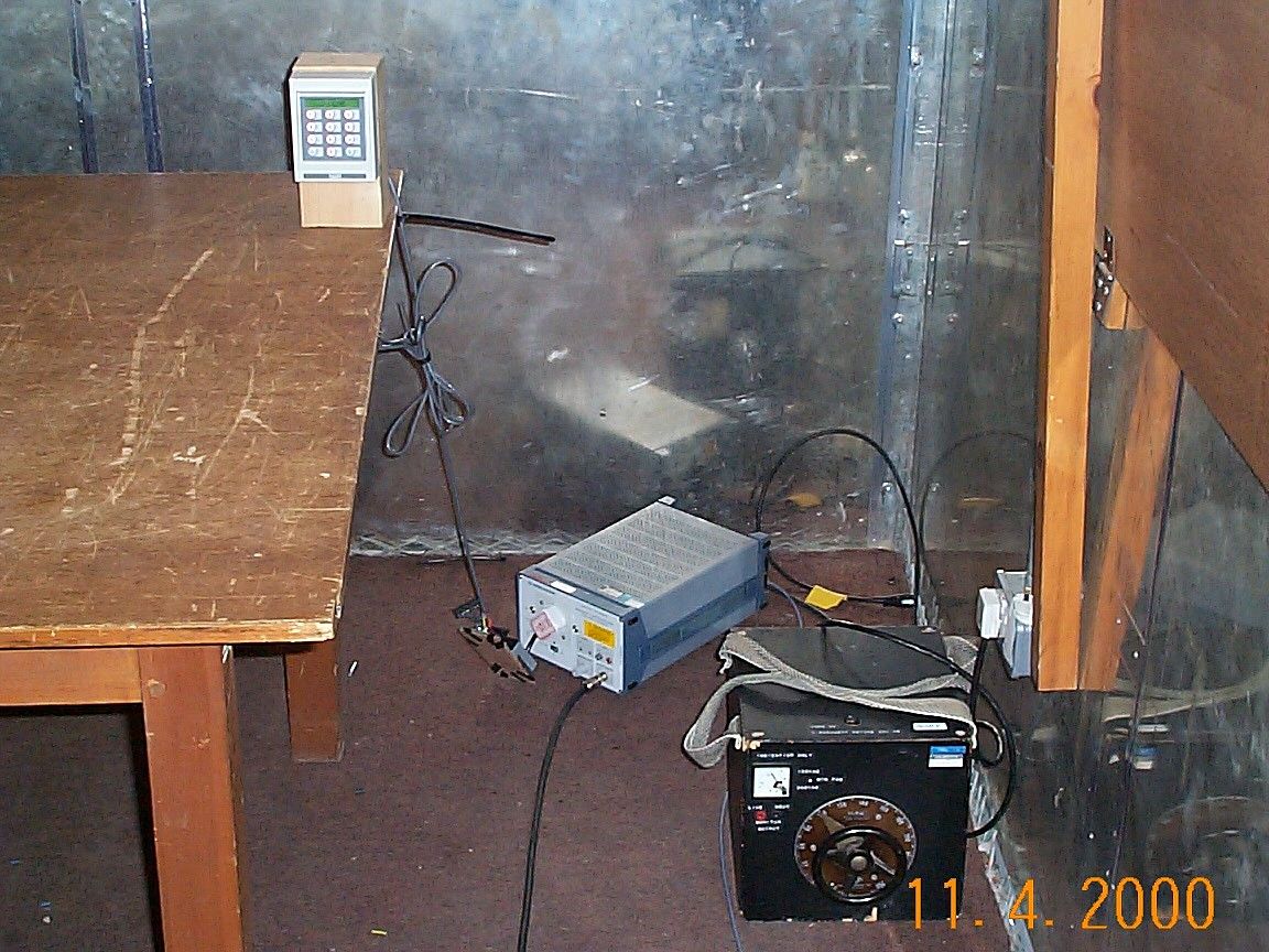
RL1051/5158Page 1 of 31 RF196-iss01 TEST REPORT NO:RL1051/5158 COPY NO:............ ISSUE NO:1 REPORT ON THE CERTIFICATION TESTING OF A GROUP 4 TECHNOLOGY Ltd. S711 READER:- MODEL 8000-5244-A IDENTITY TAG DATA TRANSCEIVER S/No. 001-000049 WITH RESPECT TO THE FCC 47CFR, Pt==s 15.107, 15.109, 15.207 & 15.225 INTENTIONAL RADIATOR & UNINTENTIONAL RADIATOR CLASS B SPECIFICATIONS TEST DATE(s): 11 th to 20 th April 2000 TESTED BY:....................................................R P I PARRY APPROVED BY:....................................................S P HAYES ISSUE DATE:.................................................... Distribution Copy No==s:- 1Group 4 Technology Ltd. 2FCC Evaluation Laboratories 3TRL EMC Ltd. RL1051/5158Page 2 of 31 RF196-iss01 CONTENTS page APPLICANT'S SUMMARY3 CERTIFICATE OF CONFORMITY & COMPLIANCE4 DESCRIPTION OF TRANSCEIVER4 EQUIPMENT TEST CONDITIONS5 TESTS REQUIRED6 SAMPLE CALCULATIONS6 TEST RESULTS7 - 17 PHOTOGRAPHSANNEX A[X] PHOTOGRAPH No 1:Test site with Tx/Rx, conducted & radiated.ANNEX A1 PHOTOGRAPH No 2:Tx/Rx, front.ANNEX A2 PHOTOGRAPH No 3:Tx/Rx, rear.ANNEX A3 PHOTOGRAPH No 4:Tx/Rx, rf & display pcb, top.ANNEX A4 PHOTOGRAPH No 5:Tx/Rx, rf & display pcb, bottom.ANNEX A5 PHOTOGRAPH No 6: Tx/Rx, rf & display pcb, w/o Ae.ANNEX A6 PHOTOGRAPH No 7:Control pcb, top.ANNEX A7 PHOTOGRAPH No 8:Control pcb, bottom.ANNEX A8 TEST EQUIPMENT LISTANNEX B [X] APPLICANT'S SUBMISSION OF DOCUMENTATION LISTANNEX C[n/a] MEASURING DISTANCE EXTRAPOLATION GRAPH(s)ANNEX D[X] TRANSMITTER CARRIER FREQUENCY GRAPH(s)ANNEX E[n/a] Notes:- 1. Component failure during testYES[ ] NO[X] 1. If Yes, details of failure:- 1. All measurement uncertainty calculations detailed in this report are carried out in accordance with UKAS Publication NIS 81, Edition 1, May 1994, for a 95% confidence level. 1. The contents of the attached applicant=s declarations and other supplied information are not covered by the scope of this laboratory=s UKAS or FCC accreditations and is provided in good faith. RL1051/5158Page 3 of 31 RF196-iss01 APPLICANT'S SUMMARY EQUIPMENT UNDER TEST (EUT):S711 Reader:- Model 8000-5244-A EQUIPMENT TYPE:Identity Tag Data Transceiver SERIAL NUMBER OF EUT:S/No. 001-000049 PURPOSE OF TEST:FCC Certification TEST SPECIFICATION(s):FCC 47CFR Pt=s 15.107, 15.109, 15.207 & 15.225 TEST RESULT:CompliantYes[X] No[ ] APPLICANT=S CATEGORY:( a ) Manufacturer[X] ( b ) Importer[ ] ( c ) Distributor[ ] ( d ) Agent[ ] APPLICANT'S ORDER No(s):P10361 APPLICANT=S CONTACT PERSON:Mr. Eric Porter APPLICANT:Group 4 Technology Ltd. ADDRESS:Challenge House, Northway Lane, Tewkesbury, Glos., GL20. 8JG., United Kingdom Tel:- +441684 850977 Fax:- +441684 290166 MANUFACTURER:Group 4 Technology Ltd. ADDRESS:Challenge House, Northway Lane, Tewkesbury, Glos., GL20. 8JG., United Kingdom Tel:- +441684 850977 Fax:- +441684 290166 EUT(s) COUNTRY OF ORIGIN:United Kingdom TEST LABORATORY:TRL EMC Ltd. UKAS ACCREDITATION No:0728 TEST DATE(s):11 th to 20 th April 2000 TEST REPORT No:RL1051/5158 RL1051/5158Page 4 of 31 RF196-iss01 CERTIFICATE OF CONFORMITY & COMPLIANCE FCC IDENTITY:OE5S711 PURPOSE OF TEST:FCC Certification TEST SPECIFICATION:FCC 47CFR, Parts 15.107, 15.109, 15.207 & 15.225 TEST RESULT:Compliant to specification EQUIPMENT UNDER TEST:S711 Reader:- Model 8000-5244-A EQUIPMENT SERIAL No:S/No. 001-000049 ITU EMISSION CODE:14k0L1D EQUIPMENT TYPE:Identity Tag Data Transceiver UTILISATION:Identification and access control CARRIER EMISSION:+22.1dBFV/m @ 30m ANTENNA TYPE:Fixed, or Integral ALTERNATIVE AE:None, as per Part 15.203 BAND OF OPERATION:13.553MHz to 13.567MHz CHANNEL SPACING:not applicable No. of CHANNELS:1 (one) FREQUENCY CONVERSION:Superhet[ ] ;Direct[X] ;Regenerative[ ] INTERMEDIATE FREQUENCY:1 ST [n/a] ;2 ND [n/a] ;3 RD [n/a] LOCAL OSCILLATOR:Higher[ ] ;Lower[ ] ;not applicable[X] FREQUENCY GENERATION:SAW Resonator[ ] ;Crystal[X] ;Synthesizer[ ] MODULATION METHOD:Amplitude [ ] ;Digital [X] ;Angle[ ] POWER SOURCE(s):110Vac TEST DATE(s):11 th to 20 th April 2000 ORDER No(s):P10361 APPLICANT:Group 4 Technology Ltd., Challenge House, Northway Lane, Tewkesbury, Glos., GL20. 8JG., United Kingdom TESTED BY:...............................................................R P I PARRY APPROVED BY:...............................................................S P HAYES EMC MANAGER RL1051/5158Page 5 of 31 RF196-iss01 EQUIPMENT TEST CONDITIONS 1. EQUIPMENT SERIAL / MODEL IDENTITY CHANNEL NUMBER Tx NOMINAL FREQUENCY MHz Rx NOMINAL FREQUENCY MHz TESTS REQUIRED REMARKS Rx ac cond.Part 15.107 Rx radiatedPart 15.109 Rx radiatedPart 15.209 Tx ac cond.Part 15.207 Tx radiatedPart 15.209 Tx carrierPart 15.225 S711 Reader113.56013.560 Tx frequencyPart 15.225 1. Equipment category:Single channel[X] Two channel[ ] Multi-channel[ ] 1. Supply voltages:Vnom=110Vac Note:-Vnom voltages are as stated above unless otherwise shown on the test report page. 1. Temperatures:(Ambient)Tnom=[see test] (Extreme)Tmin=-20 C (Extreme)Tmax=+50 C 1. Transmitter maximum deviation or shift:kHz=n/a 1. Transmitter maximum bit or pulse rate & level:bps=106k Level=proprietary serial com 1. Receiver rated output & impedance:dBW=proprietary serial com Ohms=20mA loop 1. Channel spacing:kHz=n/a Narrowband[X] Wholeband[ ] RL1051/5158Page 6 of 31 RF196-iss01 TESTS REQUIRED TRANSMITTER & RECEIVER TESTS Receiver Spurious Emissions- Powerline- Part 15.107[X] Receiver Spurious Emissions- Radiated- Part 15.109 - >30MHz[X] Receiver Spurious Emissions- Radiated- Part 15.209 - <30MHz[X] Transmitter Spurious Emissions - Powerline- Part 15.207[X] Transmitter Spurious Emissions - Radiated- Part 15.209.c- <30MHz[X] Transmitter Spurious Emissions - Radiated- Part 15.209.c- >30MHz[X] Transmitter Carrier Emission - Radiated- Part 15.225.a[X] Transmitter Carrier Frequency- Radiated- Part 15.225.c[X] Notes:- 1. Equipment tested for (mains ac) 110V powerline emissions.[X] 1. Equipment tested as (fixed) integral antenna configuration.[X] 1. All tests were carried out with new batteri…
Text truncated - open the document above for the full version.
Contact Information
Applicant
ANDY WATTS(Mr)
Test Firm
TRL EMC LimitedNeil Roche
Technical Specifications
| # | Rule Parts | Frequency Range | Power Output |
|---|---|---|---|
| 1 | 15C | 13.553 MHz - 13.567 MHz | - |
Other Applications from G4S Technology Limited
OE5S870C
Dec 22, 2025Proximity card reader with keypad for access control systems
Equipment Class
DCD - Part 15 Low Power Transmitter Below 1705 kHz
OE5S884C
Dec 22, 2025Access Control Keypad Reader 884 MKII
Equipment Class
DXX - Part 15 Low Power Communication Device Transmitter
OE5S874C
Dec 19, 2025Smartcard reader with keypad for access control systems 874 MKII
Equipment Class
DXX - Part 15 Low Power Communication Device Transmitter
OE5S884O
Jan 20, 2020S884O Proximity Reader
Equipment Class
DXX - Part 15 Low Power Communication Device Transmitter
OE5S680A
Nov 19, 2013S680 Proximity Card Reader
Equipment Class
DXX - Part 15 Low Power Communication Device Transmitter