OE5S813ES813 Enrolment Reader
G4S Technology Limited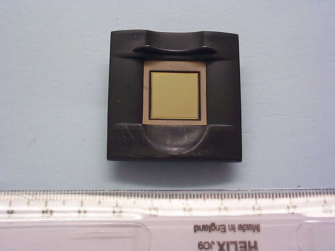
Click to zoom
Application Details
- Equipment Class
- DXX - Part 15 Low Power Communication Device Transmitter
- Date of Grant
- Mar 25, 2004
- Application Purpose
- Original Equipment
- Date of Application
- Mar 25, 2004
- Equipment Note
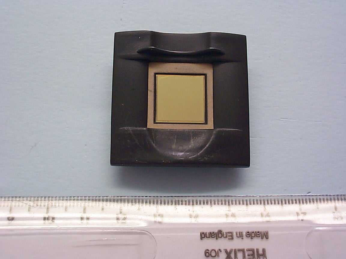
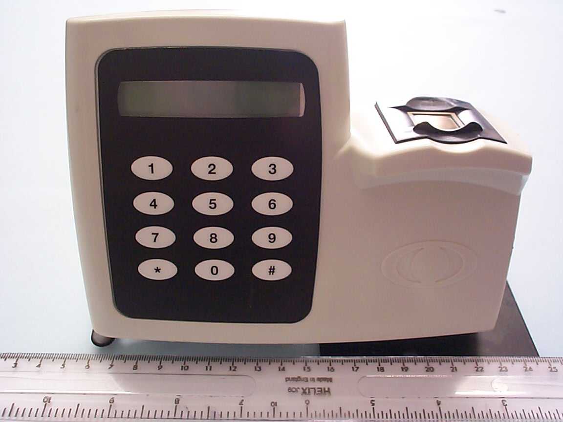
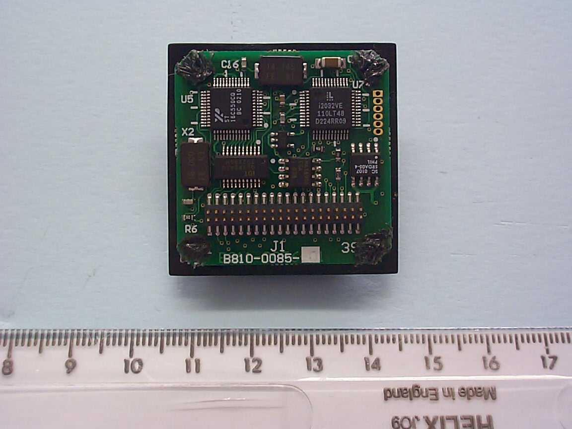
- S813 Enrolment Reader
- Frequency Range
- 13.54680000 - 13.58040000
- Company
- G4S Technology Limited
- Country
- United Kingdom
Documents & Files
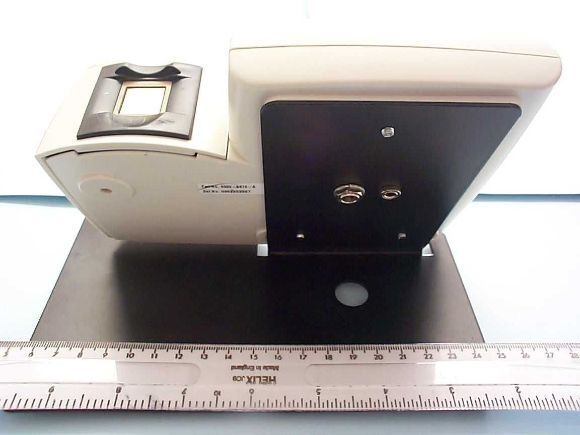
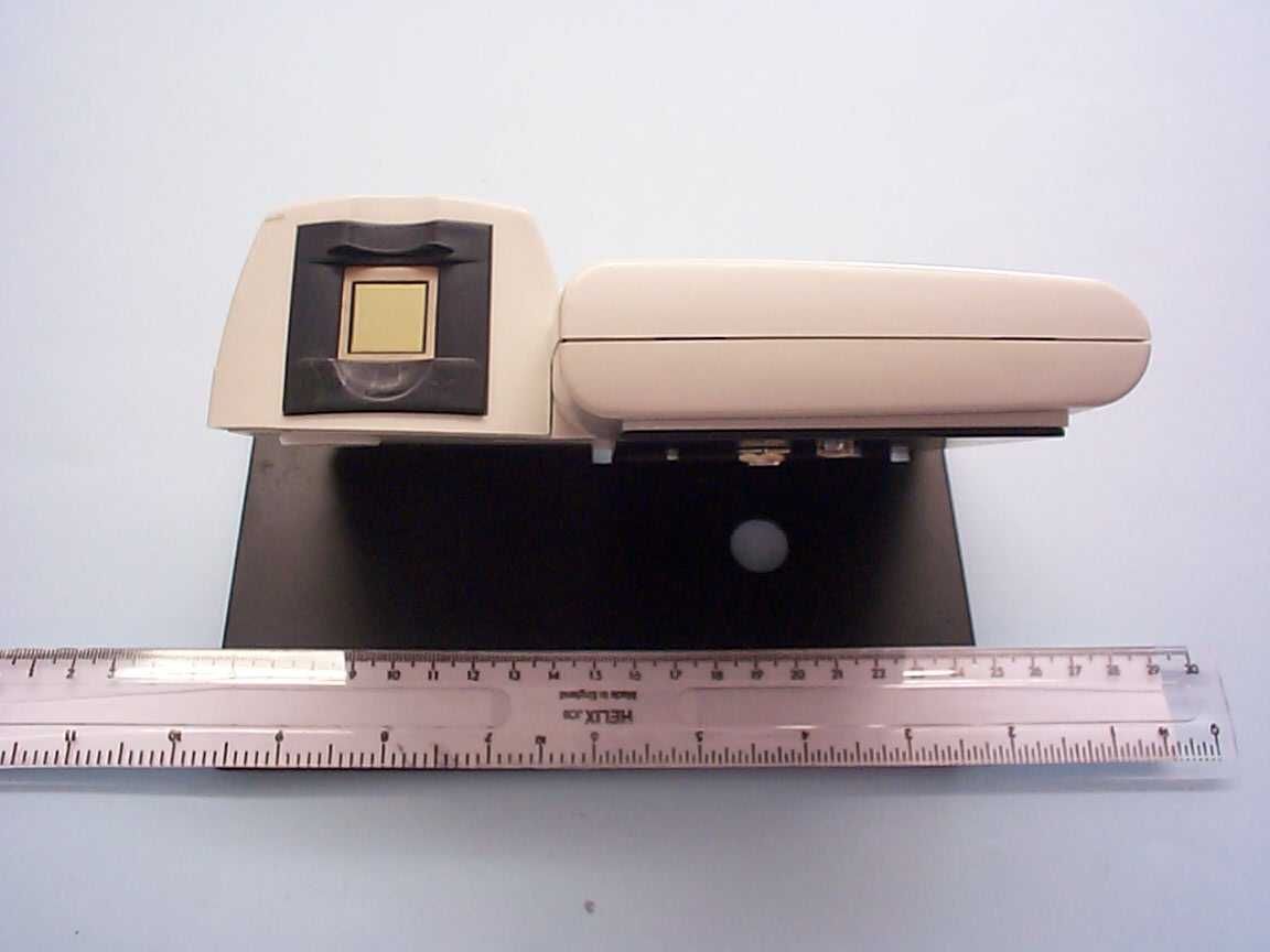
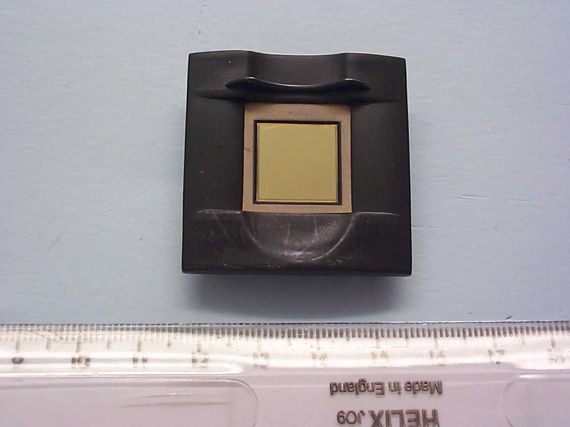
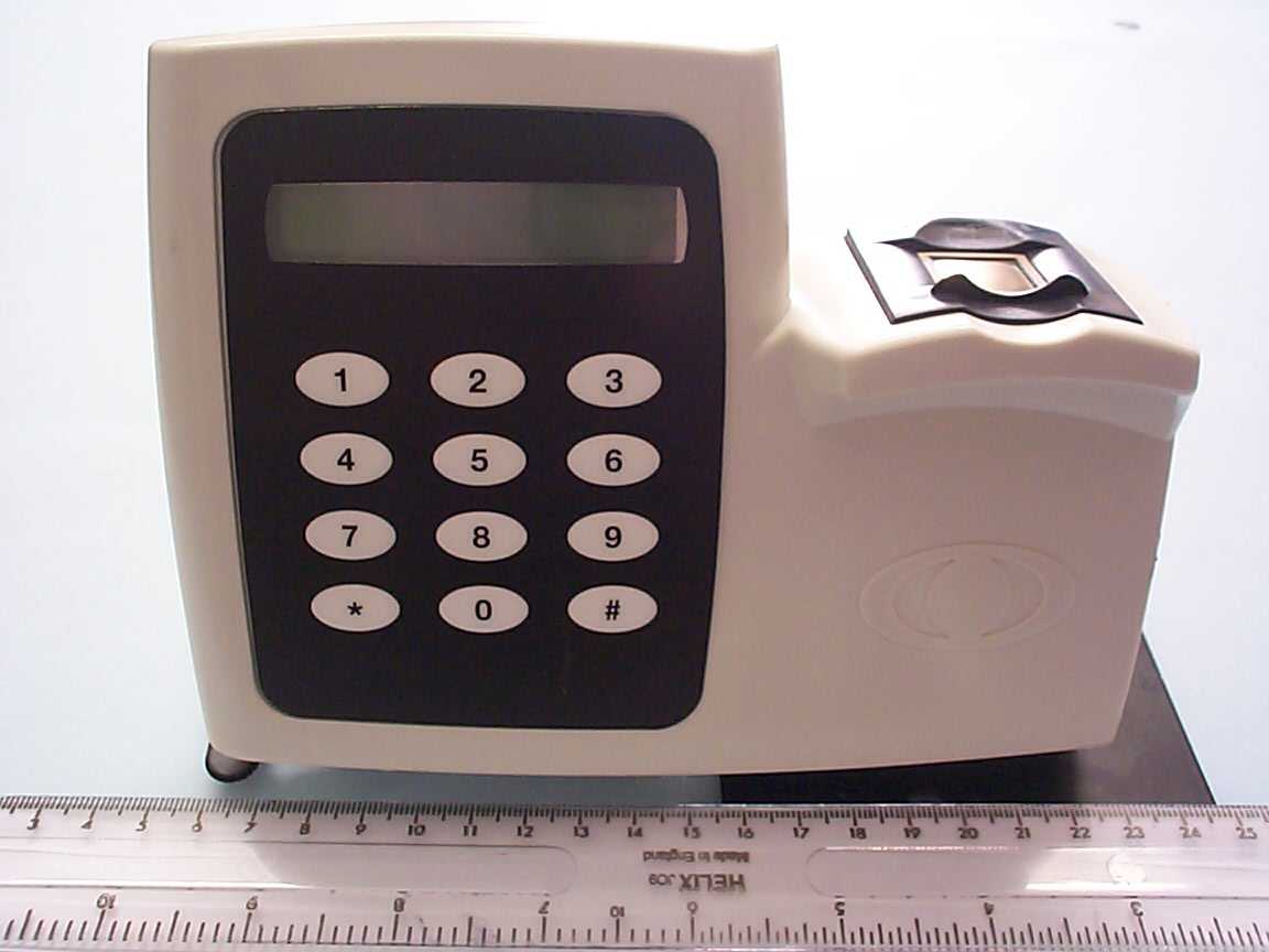
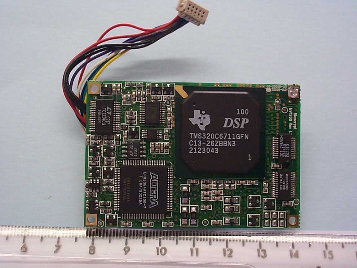
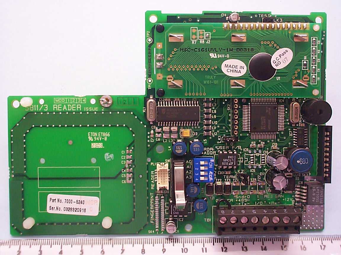
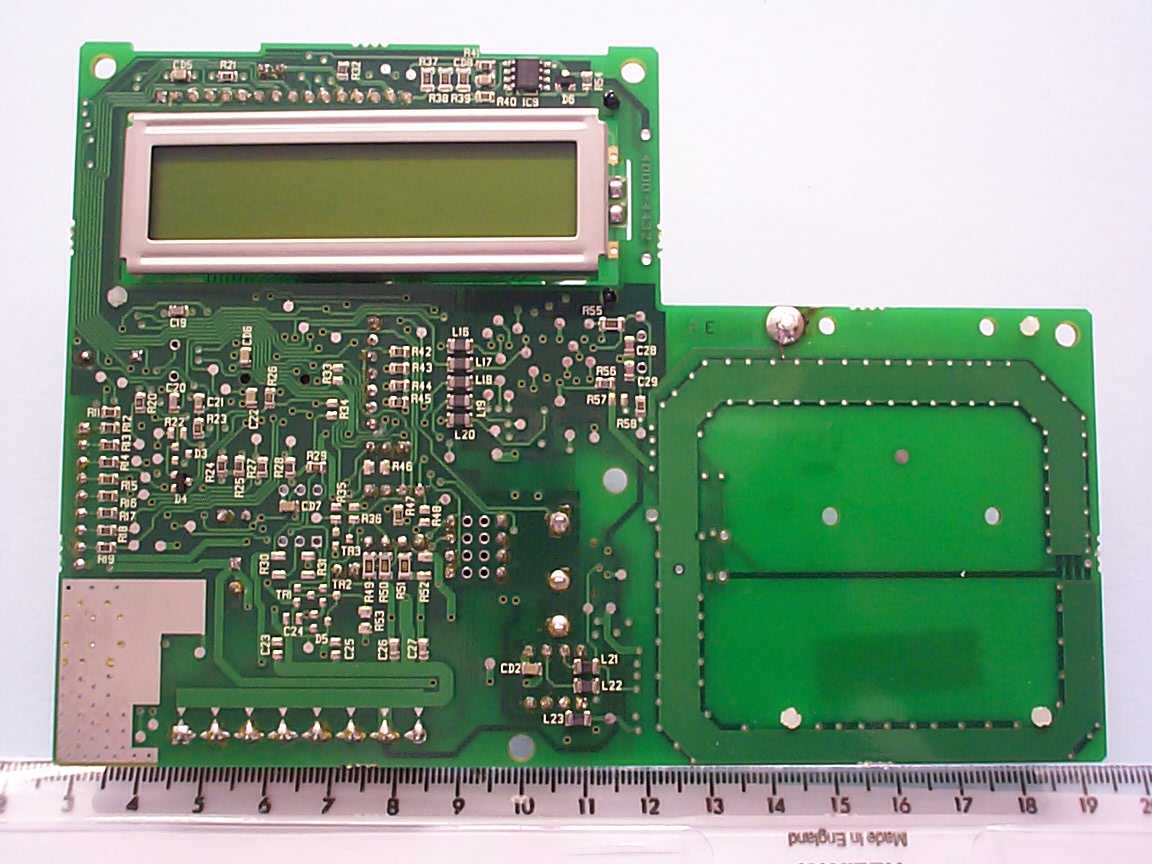
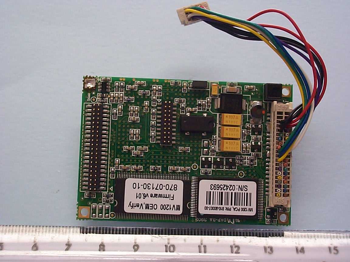
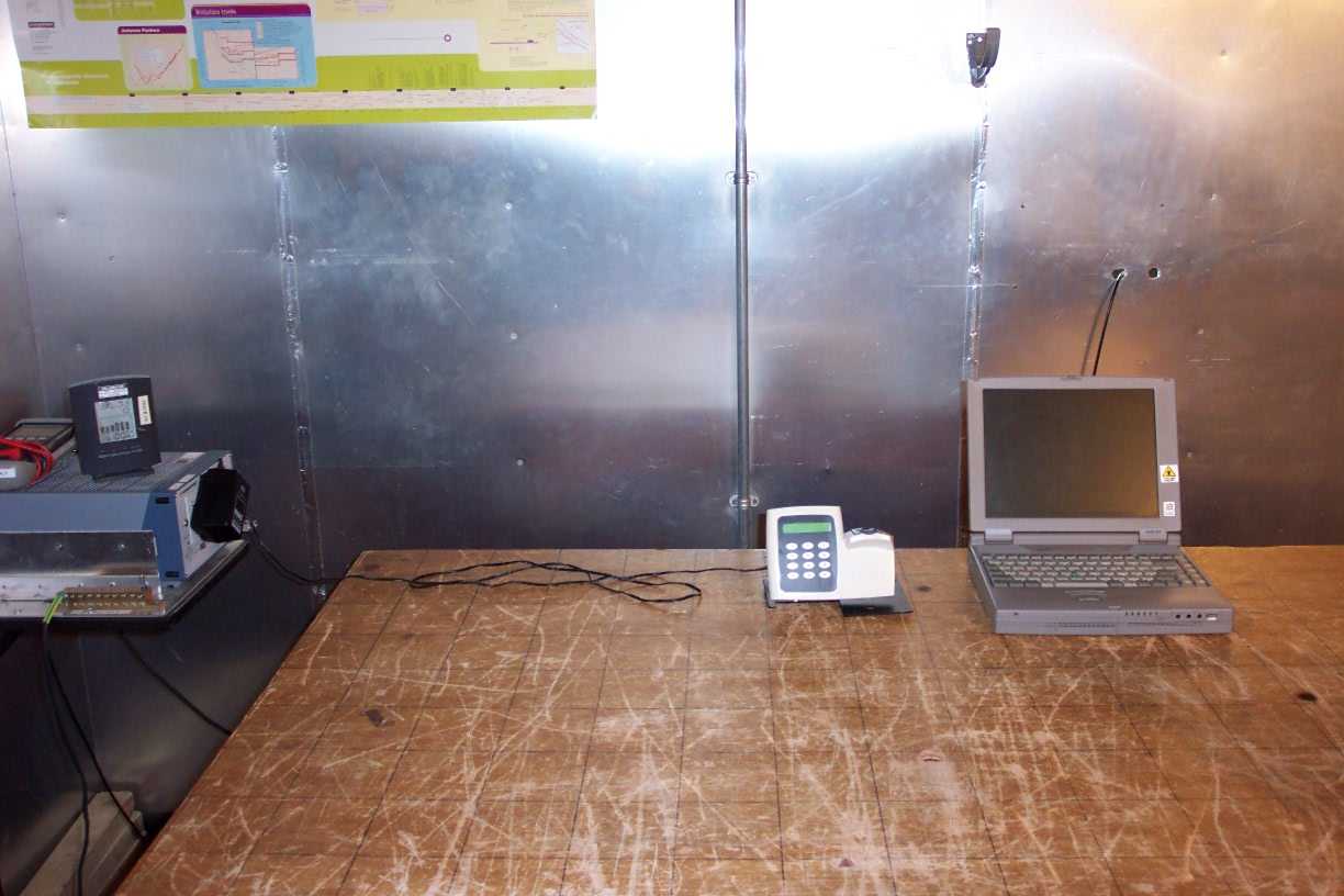
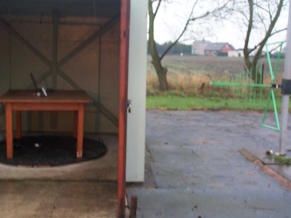
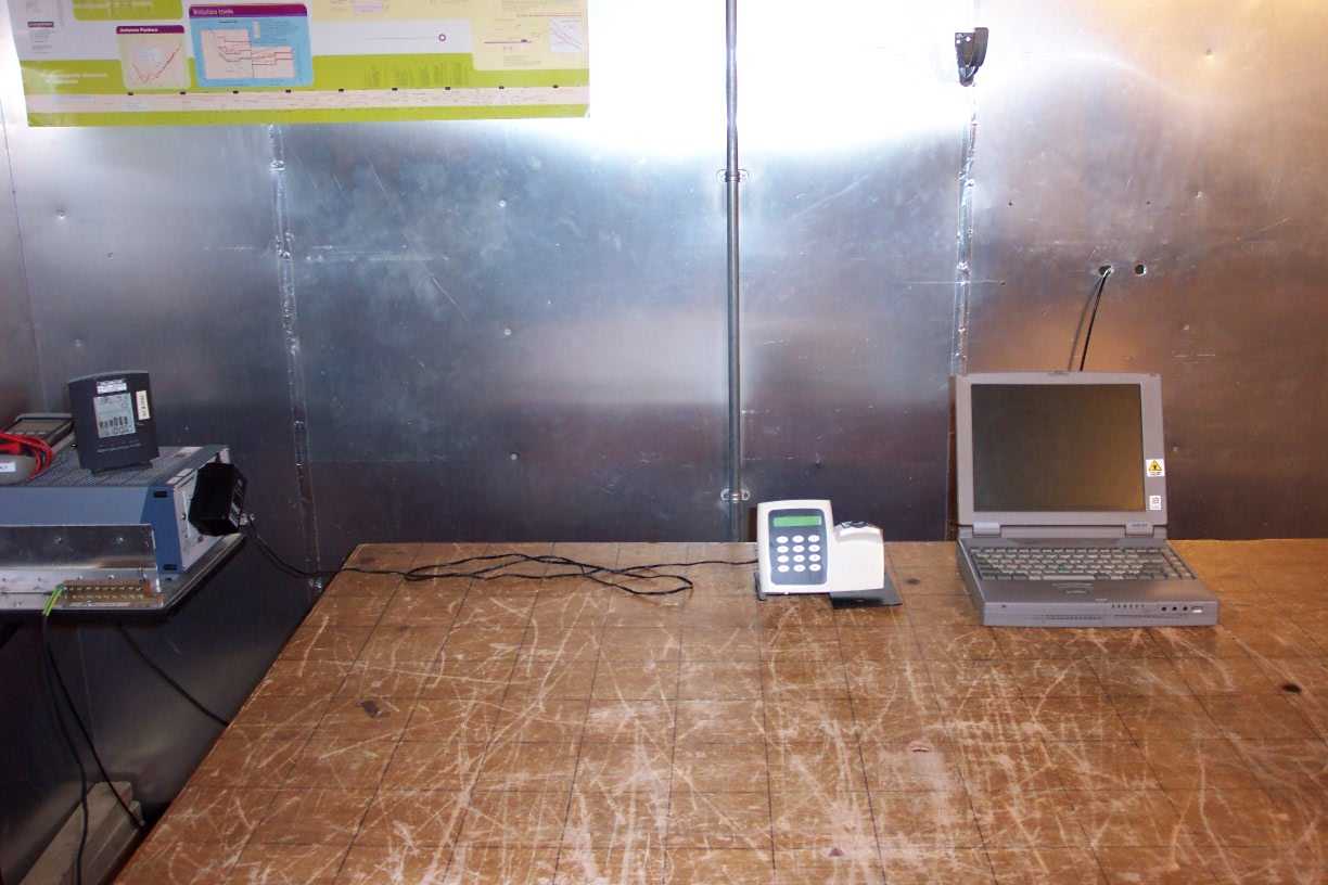
Document Text
Text extracted from the exhibit documents filed with the FCC. Open a document above to read the original.
Users Manual
Installation and User Instructions for S813 Enrollment Readers The S813 Enrollment Reader is used to capture fingerprints, and to encode Philips Philips S813 ®® MIFARE or MIFARE DESFire contactless smart cards. Theconnects to a serial port of a controlling Security Management System (SMS) PC using the supplied cable. Insert the jack plug into the socket on the back of the reader bracket. Insert the power plug into the socket on the back of the reader bracket. Connect the 12Vdc power source to the mains supply. Connect to a serial port of a PC installed with the SMS software. Set up the port in the Install/Client Ports screen of the SMS software. To use the enrollment reader: 1. Log in to the SMS software at the PC that the reader is connected to. 2. Start the fingerprint enrollment procedure from the . Follow the prompts. 3. Start the encoding procedure from the Fingerprint Enrollment screen, accessed through the Badge tab of the Card Holders screen Fingerprint Enrollment screen. When prompted, present the card to be encoded under the finger pad of the reader (tabs are provided on the base plate if you prefer to rest the card against the reader). You will hear a "bleep" when the card has been encoded. Note: Refer to the enrollment guidelines overleaf. 4 Enrollment Procedure 2 Reader Connections 1 Installation This illustration shows the connections from the reader to the RS232-to-RS485 converter and power supply. There should be no need to make these connections yourself - use the supplied cables. S813 Reader TB1 XMT- G XMT+ RS232-to-RS485 Converter 0V 0V TX+ TX- I/0 Do not use RX+ RX- +12V 12V Twisted pair Note the apparent reverse in polarity between the converter and reader (from "-" to "+" and vice versa) 12Vdc power 3 Reader Links and Switches The following links are provided on the reader's PCB: LK1(Audio feedback) - Set to "0" for sound off. Set to "1" for sound on. LK2(TERM) - Ensure that this link has been removed. LK3(TEST) - Ensure that this link has been removed. Ensure that all bit switches in SW2 (RDR ADDR) are set to the OFF position. 9600-0334.Installation and User Instructions for S813 Enrollment Readers, Issue 1.1 30th January 2004.Group 4 Technology, 2003-2004. FCC Notice:This device complies with Part 15 of the FCC Rules. Operation is subject to the following two conditions: (1) This device may not cause harmful interference, and (2) this device must accept any interference received, including interference that may cause undesired operation. Any unauthorized modification to this device may void the authority of the user to operate it. All trademarks acknowledged. Philips and MIFARE are registered trademarks of Philips Electronics, N.V. © Specifications Input voltage: 9-14V. Input current: 250mA @ nominal 12Vdc supply. Operating temperature: 32 to 122 F (0 to 50 C). Operating humidity: 15 to 90%, non-condensing. Maximum encoding range: 1" (25mm). Approvals: EN50133, R&TTE, IP605. For internal use only. °° Use the following tips to ensure good enrollment. F - Set the Acceptance Threshold When a fingerprint is presented to an S813 Fingerprint Reader during an access-control transaction, it is compared against the fingerprint stored on the card and a score is produced. The closer the match, the higher the score. To gain entry, the score calculated by the reader must be greater than or equal to the acceptance threshold specified in the Fingerprint Enrollment screen. The default acceptance threshold is specified in the Configure/Preferences screen. You can specify a different value by selectingin the Fingerprint Enrollment screen. The specified value is stored on the card during encoding. Too high a value may result in a reader not being able to confirm identity. Too low a value may result in poor security. You cannot change the acceptance threshold to be less than the minimum allowed setting in your user privileges (Configure/User/Accounts). The card-level acceptance threshold can be overridden for a specified reader in the Install/Devices/Readers screen. This may be useful for readers in high-security areas. Custom Acceptance Threshold Note: ! ! ! Quality: Content: Good. Core is properly centered. Surface area and ridge pattern are well defined. Quality: Content: More pressure is needed to improve the image. Enroll again. Core is properly centered. Quality: Content: Poor - ridges are not well defined. Enroll using a different finger that provides a better image. Core is properly centered, but is not well defined. Quality: Content: Good. Core is not centered. The same finger should be enrolled again. 5 Tips for Good Fingerprint Enrollment D - Check the Displayed Fingerprint Core Check the displayed fingerprint in the Fingerprint Enrollment screen. Make sure that the fingerprint core is centered in the Fingerprint Image box. Here are examples of typical cores: A - Use the Correct Fingers Use index, middle or ring fingers (not thumbs or little fingers): B - Place Finger Correctly Make sure each finger is placed with the first joint of the finger resting on the raised ridge at the front of the sensor. Cover as much of the sensor area as possible with the finger: C - Apply Moderate Pressure Too much pressure may cause smudging of the fingerprint. Too little pressure may prevent the ridge patterns from being captured. Examples: E - Check the Quality and Content Manually check the quality and content of each fingerprint displayed in the Fingerprint Enrollment screen. The Quality and Content indicators show estimated quality and content scores. The indicators are shown in green if the estimated scores match or exceed the minimum values set in the Configure/ User/Accounts screen. The indicators are shown in red if this is not the case. INCORRECT û CORRECT ü
Users Manual
Installation and User Instructions for S813 Enrollment Readers The S813 Enrollment Reader is used to capture fingerprints, and to encode Philips Philips S813 ®® MIFARE or MIFARE DESFire contactless smart cards. Theconnects to a serial port of a controlling Security Management System (SMS) PC using the supplied cable. Insert the jack plug into the socket on the back of the reader bracket. Insert the power plug into the socket on the back of the reader bracket. Connect the 12Vdc power source to the mains supply. Connect to a serial port of a PC installed with the SMS software. Set up the port in the Install/Client Ports screen of the SMS software. To use the enrollment reader: 1. Log in to the SMS software at the PC that the reader is connected to. 2. Start the fingerprint enrollment procedure from the . Follow the prompts. 3. Start the encoding procedure from the Fingerprint Enrollment screen, accessed through the Badge tab of the Card Holders screen Fingerprint Enrollment screen. When prompted, present the card to be encoded under the finger pad of the reader (tabs are provided on the base plate if you prefer to rest the card against the reader). You will hear a "bleep" when the card has been encoded. Note: Refer to the enrollment guidelines overleaf. 4 Enrollment Procedure 2 Reader Connections 1 Installation This illustration shows the connections from the reader to the RS232-to-RS485 converter and power supply. There should be no need to make these connections yourself - use the supplied cables. S813 Reader TB1 XMT- G XMT+ RS232-to-RS485 Converter 0V 0V TX+ TX- I/0 Do not use RX+ RX- +12V 12V Twisted pair Note the apparent reverse in polarity between the converter and reader (from "-" to "+" and vice versa) 12Vdc power 3 Reader Links and Switches The following links are provided on the reader's PCB: LK1(Audio feedback) - Set to "0" for sound off. Set to "1" for sound on. LK2(TERM) - Ensure that this link has been removed. LK3(TEST) - Ensure that this link has been removed. Ensure that all bit switches in SW2 (RDR ADDR) are set to the OFF position. 9600-0334.Installation and User Instructions for S813 Enrollment Readers, Issue 1.1 30th January 2004.Group 4 Technology, 2003-2004. FCC Notice:This device complies with Part 15 of the FCC Rules. Operation is subject to the following two conditions: (1) This device may not cause harmful interference, and (2) this device must accept any interference received, including interference that may cause undesired operation. Any unauthorized modification to this device may void the authority of the user to operate it. All trademarks acknowledged. Philips and MIFARE are registered trademarks of Philips Electronics, N.V. © Specifications Input voltage: 9-14V. Input current: 250mA @ nominal 12Vdc supply. Operating temperature: 32 to 122 F (0 to 50 C). Operating humidity: 15 to 90%, non-condensing. Maximum encoding range: 1" (25mm). Approvals: EN50133, R&TTE, IP605. For internal use only. °° Use the following tips to ensure good enrollment. F - Set the Acceptance Threshold When a fingerprint is presented to an S813 Fingerprint Reader during an access-control transaction, it is compared against the fingerprint stored on the card and a score is produced. The closer the match, the higher the score. To gain entry, the score calculated by the reader must be greater than or equal to the acceptance threshold specified in the Fingerprint Enrollment screen. The default acceptance threshold is specified in the Configure/Preferences screen. You can specify a different value by selectingin the Fingerprint Enrollment screen. The specified value is stored on the card during encoding. Too high a value may result in a reader not being able to confirm identity. Too low a value may result in poor security. You cannot change the acceptance threshold to be less than the minimum allowed setting in your user privileges (Configure/User/Accounts). The card-level acceptance threshold can be overridden for a specified reader in the Install/Devices/Readers screen. This may be useful for readers in high-security areas. Custom Acceptance Threshold Note: ! ! ! Quality: Content: Good. Core is properly centered. Surface area and ridge pattern are well defined. Quality: Content: More pressure is needed to improve the image. Enroll again. Core is properly centered. Quality: Content: Poor - ridges are not well defined. Enroll using a different finger that provides a better image. Core is properly centered, but is not well defined. Quality: Content: Good. Core is not centered. The same finger should be enrolled again. 5 Tips for Good Fingerprint Enrollment D - Check the Displayed Fingerprint Core Check the displayed fingerprint in the Fingerprint Enrollment screen. Make sure that the fingerprint core is centered in the Fingerprint Image box. Here are examples of typical cores: A - Use the Correct Fingers Use index, middle or ring fingers (not thumbs or little fingers): B - Place Finger Correctly Make sure each finger is placed with the first joint of the finger resting on the raised ridge at the front of the sensor. Cover as much of the sensor area as possible with the finger: C - Apply Moderate Pressure Too much pressure may cause smudging of the fingerprint. Too little pressure may prevent the ridge patterns from being captured. Examples: E - Check the Quality and Content Manually check the quality and content of each fingerprint displayed in the Fingerprint Enrollment screen. The Quality and Content indicators show estimated quality and content scores. The indicators are shown in green if the estimated scores match or exceed the minimum values set in the Configure/ User/Accounts screen. The indicators are shown in red if this is not the case. INCORRECT û CORRECT ü
ID Label/Location Info
S813 Encoder Fingerprint Reader Label Product and Approvals Label ( 25mm x 30mm ) Label Positioning ( The label will be placed on the back of the unit as shown below ) Issue 1 Group 4 Technology Ltd. Model: 8000-5650-A Serial No: 0321000001 9-14V DC 350mA FCC ID: OE5S813E Label Position 090304
ID Label/Location Info
S813 Encoder Fingerprint Reader Label Product and Approvals Label ( 25mm x 30mm ) Label Positioning ( The label will be placed on the back of the unit as shown below ) Issue 1 Group 4 Technology Ltd. Model: 8000-5650-A Serial No: 0321000001 9-14V DC 350mA FCC ID: OE5S813E Label Position 090304
Test Report
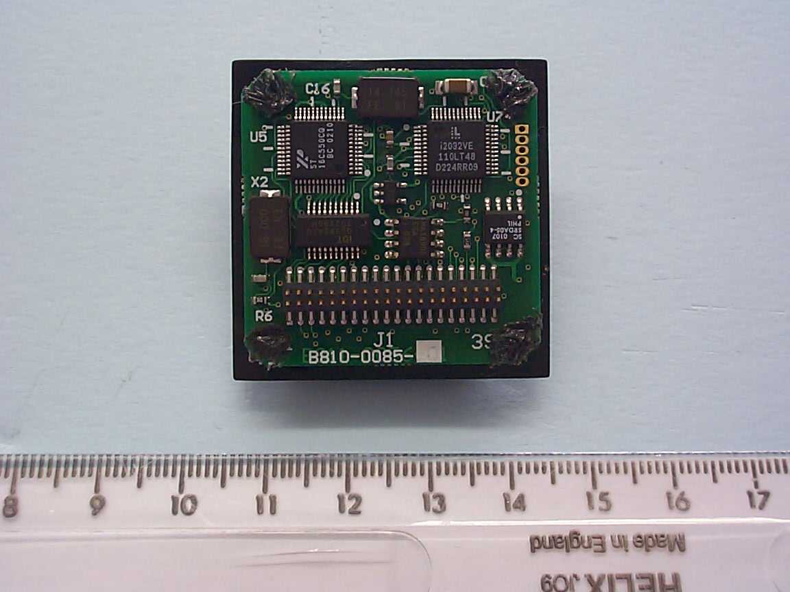
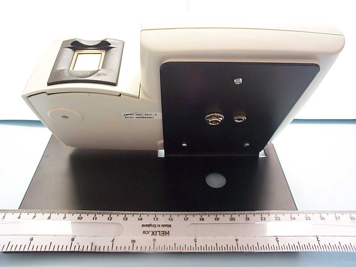
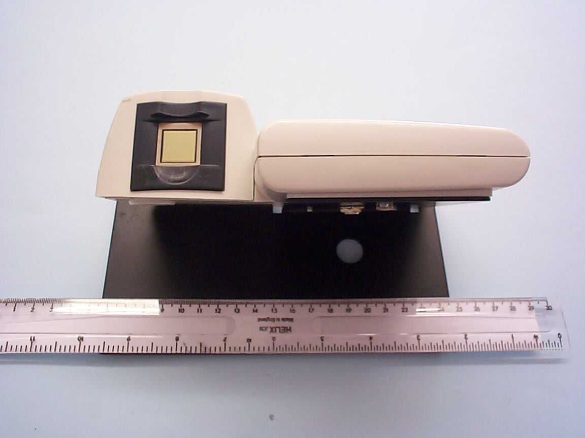
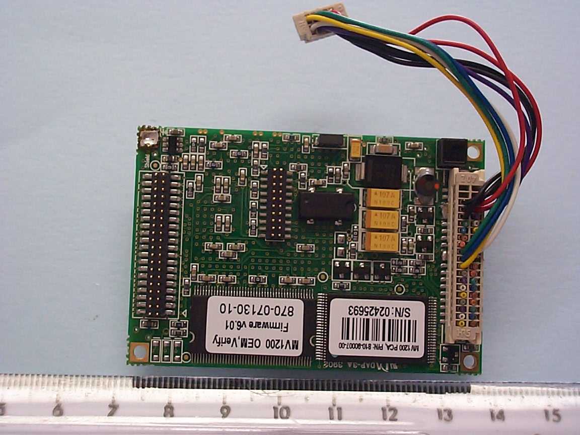
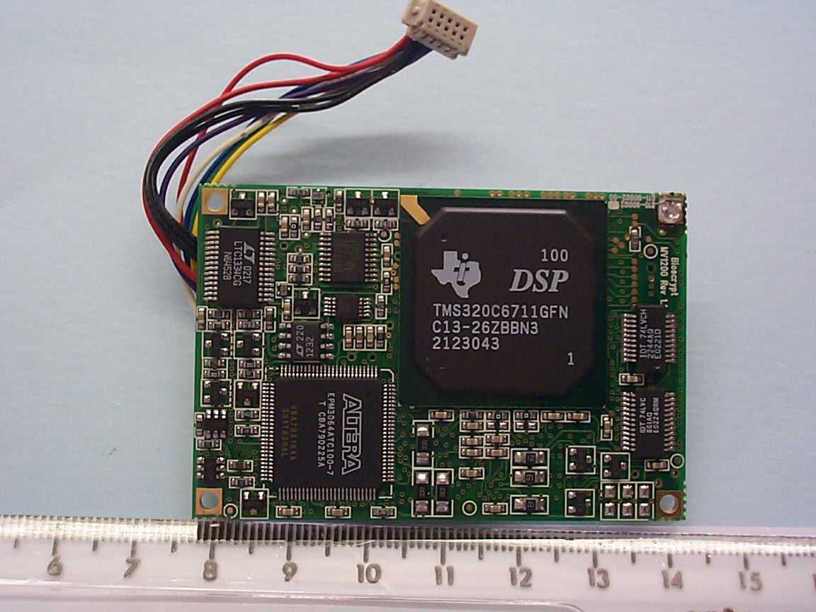
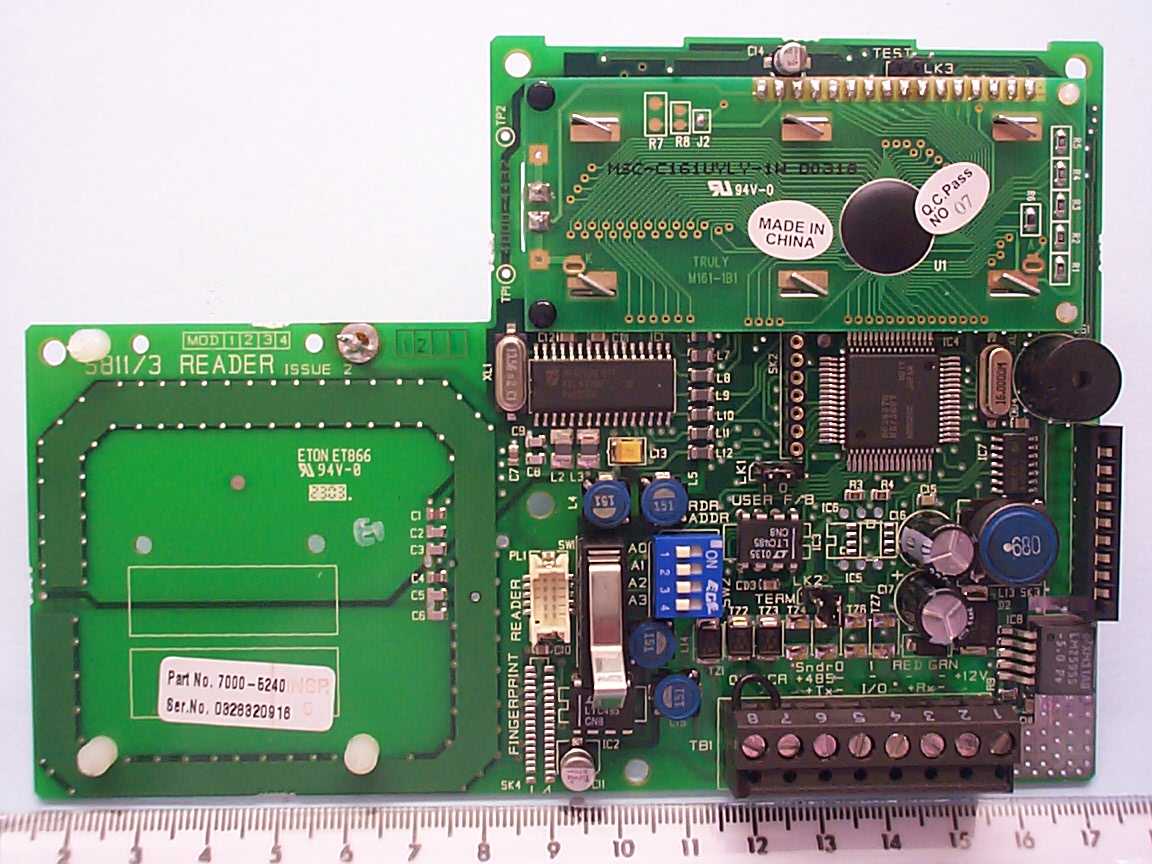
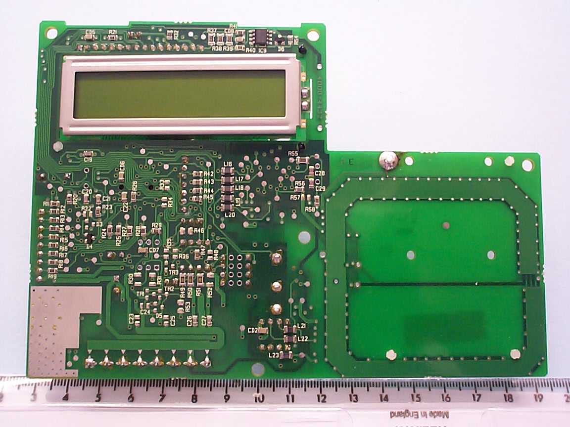
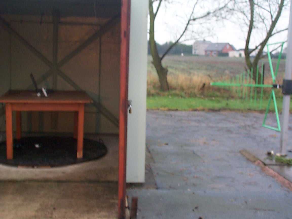
TRL C OMPLIANCE S ERVICES L TD EMC DIVISION MOSS VIEW NIPE LANE UP HOLLAND WEST LANCASHIRE WN8 9PY UNITED KINGDOM TELEPHONE +44 (0)1695 556666 FAX +44 (0)1695 557077 E- MAIL [email protected] www.trlcompliance.com 0728 FS 21805 TEST REPORT NO:RU1091/5370 COPY NO:2 ISSUE NO:1 FCC ID:OE5S813E REPORT ON THE CERTIFICATION TESTING OF A Group 4 Technology Ltd S813 Enrolment Reader WITH RESPECT TO THE FCC RULES CFR 47, PART15.225 INTENTIONAL RADIATOR SPECIFICATION TEST DATE: 25 th November – 4 th December 2003 TESTED BY:J Charters APPROVED BY:P GREEN EMC Product Manager DATE:11 th March 2004 Distribution: Copy Nos:1.Group 4 Technology Ltd 2.TCB :TRL Compliance Services 3.TRL EMC THIS DOCUMENT MAY BE REPRODUCED ONLY IN ITS ENTIRETY AND WITHOUT CHANGE RF335U iss03RU1091/5370Page 2 of 31 CONTENTS PAGE CERTIFICATE OF CONFORMITY & COMPLIANCE3 APPLICANT’S SUMMARY4 EQUIPMENT TEST CONDITIONS4 TESTS REQUIRED5 TEST RESULTS6-14 ANNEX PHOTOGRAPHSA PHOTOGRAPH No. 1: Test setup PHOTOGRAPH No. 2: Transmitter front view PHOTOGRAPH No. 3: Transmitter rear view PHOTOGRAPH No. 4: Transmitter PCB front PHOTOGRAPH No. 5: Transmitter PCB rear PHOTOGRAPH No. 6: Finger print reader front PHOTOGRAPH No. 7: Finger print reader rear PHOTOGRAPH No. 8: PCB 2 front PHOTOGRAPH No. 9: PCB 2 rear APPLICANT’S SUBMISSION OF DOCUMENTATION LISTB BAND OCCUPANCY PLOTC SCAN DATAD Notes: 1.Component failure during testYES NO [ ] [X] 2.If Yes, details of failure: 3.The facilities used for the testing of the product contain in this report are FCC Listed. 4.The contents of the attached applicants declarations and other supplied information are not covered by the scope of this laboratory’s UKAS or FCC accreditations’ and is provided in good faith. RF335U iss03RU1091/5370Page 3 of 31 CERTIFICATE OF CONFORMITY & COMPLIANCE FCC IDENTITY:OE5S813E PURPOSE OF TEST:Certification TEST SPECIFICATION:FCC RULES CFR 47, PART15.225 TEST RESULT:Compliant to Specification EQUIPMENT UNDER TEST:S813 Enrolment Reader EQUIPMENT SERIAL No:0332332397 ITU: EMISSION CODE:12K0A1D EQUIPMENT TYPE:Enrolment Reader PRODUCT USE:Access control CARRIER EMISSION: 15.524μV/m @ 30 m ANTENNA TYPE:Integral ALTERNATIVE ANTENNA:N/A BAND OF OPERATION:13.110MHz – 14.010MHz CHANNEL SPACING:N/A wideband NUMBER OF CHANNELS:1 FREQUENCY GENERATION:SAW Resonator[ ]Crystal[X]Synthesiser [ ] MODULATION METHOD:Amplitude[ ]Digital[X]Angle [ ] POWER SOURCE(s):+12Vdc TEST DATE(s):25 th November – 4 th December 2003 ORDER No(s):R000016004 APPLICANT:Group 4 Technology Ltd ADDRESS:Challenge House Northway Lane Tewkesbury Gloucester GL19 4QH United Kingdom TESTED BY:J Charters APPROVED BY:P Green EMC Product Manager RF335U iss03RU1091/5370Page 4 of 31 APPLICANT’S SUMMARY EQUIPMENT UNDER TEST (EUT):S813 Enrolment Reader EQUIPMENT TYPE:Enrolment Reader SERIAL NUMBER OF EUT:0332332397 PURPOSE OF TEST:Certification TEST SPECIFICATION(s):FCC RULES CFR 47, PART15.225 TEST RESULT:COMPLIANTYes No [X] [ ] APPLICANT’S CATEGORY:MANUFACTURER IMPORTER DISTRIBUTOR TEST HOUSE AGENT [X] [ ] [ ] [ ] [ ] APPLICANT’S ORDER No(s):R000016004 APPLICANT’S CONTACT PERSON(s):Mr E Porter E-mail address:[email protected] APPLICANT:Group 4 Technology Ltd ADDRESS:Challenge House Northway Lane Tewkesbury Gloucester GL19 4QH United Kingdom TEL:01684 299400 FAX:01684 290166 MANUFACTURER:Group 4 Technology Ltd EUT(s) COUNTRY OF ORIGIN:United Kingdom TEST LABORATORY:TRL EMC UKAS ACCREDITATION No:0728 TEST DATE(s)25 th November – 4 th December 2003 TEST REPORT No:RU1091/5370 RF335U iss03RU1091/5370Page 5 of 31 EQUIPMENT TEST / EXAMINATIONS REQUIRED 1. TEST/EXAMINATIONRULE PARTDETECTORAPPLICABILITY Intentional Emission Frequency:15.225Quasi PeakYes Intentional Emission Field Strength:15.225Quasi PeakYes Intentional Emission Band Occupancy:15.255Quasi PeakYes Intentional Emission ERP (mW):N/A-No Spurious Emissions – Conducted:15.207 Quasi Peak Average Yes Spurious Emissions – Radiated <1000MHz:15.209Quasi PeakYes Spurious Emissions – Radiated >1000MHz:N/A-No Maximum Frequency of Search:15.33-Yes Antenna Arrangements Integral:15.203-Yes Antenna Arrangements External Connector:15.204-No Restricted Bands15.205-Yes Extrapolation Factor15.31(f)-Yes 2.Product Use:Access control 3.Emission Designator:12K0A1D 4.Duty Cycle:<100% 5.Temperatures:Ambient (Tnom)10 o C 6.Supply Voltages:Vnom+12Vdc Note: Vnom voltages are as stated above unless otherwise shown on the test report page Single channel[X] Two channel[ ] 7.Equipment Category: Multi-channel[ ] Narrowband[ ] Wideband[X] 8.Channel spacing: RF335U iss03RU1091/5370Page 6 of 31 TRANSMITTER TESTS TRANSMITTER SPURIOUS EMISSIONS – RADIATED – PART 15.209 Ambient temperature=16 o C(<1GHz)3m measurements <1GHz[X] Relative humidity=49% (<1GHz),10m measurements <30MHz[X] Conditions=Open Area Test Site (OATS)30m extrapolated from 10m[X] Supply voltage=12Vdc Channel number=1 FREQ. (MHz) MEAS. Rx. (dBμV) CABLE LOSS (dB) ANT FACT. (dB/m) FIELD STRENGTH (dBμV/m) EXTRAP. FACTOR (dB) FIELD STRENGTH (μV/m) LIMIT (μV/m) 1.705MHz-30MHz27.1225.9--25.919.082.1330 30MHz- 88MHz81.425.50.86.933.2-45.7100 88MHz-216MHz 99.7 108.5 203.45 26.1 44.6 31.5 0.8 1.0 1.4 10.2 11.2 8.4 37.1 34.4 41.3 - 71.61 52.48 116.15 150 216MHz-960MHz 217.0 284.8 311.95 400.0 498.25 556.05 610.3 651.0 678.1 800.0 813.75 35.5 29.85 20.6 23.3 14.2 17.7 21.6 22.9 17.9 17.4 16.2 1.5 1.7 1.9 2.1 2.6 2.7 2.9 3.1 3.1 3.6 3.7 8.0 12.55 13.5 15.7 17.3 18.8 18.6 19.1 19.0 20.1 20.1 45.0 44.1 36.0 41.1 34.1 39.2 43.1 45.1 40.0 41.1 40.0 - - - - - - - - - - - 177.82 160.33 63.09 113.50 50.70 91.20 142.88 179.88 100.00 113.50 100.00 200 200 200 200 200 200 200 200 200 200 200 960MHz-1GHz 1GHz-5GHz 1.705MHz to 30MHz 30μV/m@ 30m 30MHz to 88MHz100μV/m@ 3m 88MHz to 216MHz150μV/m@ 3m 216MHz to 960MHz200μV/m@ 3m 960MHz to 1GHz500μV/m@ 3m Limits 1GHz to 5GHz500μV/m@ 3m See next page for the notes and test methods: RF335U iss03RU1091/5370Page 7 of 31 Notes: 1Results quoted are extrapolated as indicated 2 Emissions were searched to: (x) 1000MHz inc…
Text truncated - open the document above for the full version.
Test Report
TRL C OMPLIANCE S ERVICES L TD EMC DIVISION MOSS VIEW NIPE LANE UP HOLLAND WEST LANCASHIRE WN8 9PY UNITED KINGDOM TELEPHONE +44 (0)1695 556666 FAX +44 (0)1695 557077 E- MAIL [email protected] www.trlcompliance.com 0728 FS 21805 TEST REPORT NO:RU1091/5370 COPY NO:2 ISSUE NO:1 FCC ID:OE5S813E REPORT ON THE CERTIFICATION TESTING OF A Group 4 Technology Ltd S813 Enrolment Reader WITH RESPECT TO THE FCC RULES CFR 47, PART15.225 INTENTIONAL RADIATOR SPECIFICATION TEST DATE: 25 th November – 4 th December 2003 TESTED BY:J Charters APPROVED BY:P GREEN EMC Product Manager DATE:11 th March 2004 Distribution: Copy Nos:1.Group 4 Technology Ltd 2.TCB :TRL Compliance Services 3.TRL EMC THIS DOCUMENT MAY BE REPRODUCED ONLY IN ITS ENTIRETY AND WITHOUT CHANGE RF335U iss03RU1091/5370Page 2 of 31 CONTENTS PAGE CERTIFICATE OF CONFORMITY & COMPLIANCE3 APPLICANT’S SUMMARY4 EQUIPMENT TEST CONDITIONS4 TESTS REQUIRED5 TEST RESULTS6-14 ANNEX PHOTOGRAPHSA PHOTOGRAPH No. 1: Test setup PHOTOGRAPH No. 2: Transmitter front view PHOTOGRAPH No. 3: Transmitter rear view PHOTOGRAPH No. 4: Transmitter PCB front PHOTOGRAPH No. 5: Transmitter PCB rear PHOTOGRAPH No. 6: Finger print reader front PHOTOGRAPH No. 7: Finger print reader rear PHOTOGRAPH No. 8: PCB 2 front PHOTOGRAPH No. 9: PCB 2 rear APPLICANT’S SUBMISSION OF DOCUMENTATION LISTB BAND OCCUPANCY PLOTC SCAN DATAD Notes: 1.Component failure during testYES NO [ ] [X] 2.If Yes, details of failure: 3.The facilities used for the testing of the product contain in this report are FCC Listed. 4.The contents of the attached applicants declarations and other supplied information are not covered by the scope of this laboratory’s UKAS or FCC accreditations’ and is provided in good faith. RF335U iss03RU1091/5370Page 3 of 31 CERTIFICATE OF CONFORMITY & COMPLIANCE FCC IDENTITY:OE5S813E PURPOSE OF TEST:Certification TEST SPECIFICATION:FCC RULES CFR 47, PART15.225 TEST RESULT:Compliant to Specification EQUIPMENT UNDER TEST:S813 Enrolment Reader EQUIPMENT SERIAL No:0332332397 ITU: EMISSION CODE:12K0A1D EQUIPMENT TYPE:Enrolment Reader PRODUCT USE:Access control CARRIER EMISSION: 15.524μV/m @ 30 m ANTENNA TYPE:Integral ALTERNATIVE ANTENNA:N/A BAND OF OPERATION:13.110MHz – 14.010MHz CHANNEL SPACING:N/A wideband NUMBER OF CHANNELS:1 FREQUENCY GENERATION:SAW Resonator[ ]Crystal[X]Synthesiser [ ] MODULATION METHOD:Amplitude[ ]Digital[X]Angle [ ] POWER SOURCE(s):+12Vdc TEST DATE(s):25 th November – 4 th December 2003 ORDER No(s):R000016004 APPLICANT:Group 4 Technology Ltd ADDRESS:Challenge House Northway Lane Tewkesbury Gloucester GL19 4QH United Kingdom TESTED BY:J Charters APPROVED BY:P Green EMC Product Manager RF335U iss03RU1091/5370Page 4 of 31 APPLICANT’S SUMMARY EQUIPMENT UNDER TEST (EUT):S813 Enrolment Reader EQUIPMENT TYPE:Enrolment Reader SERIAL NUMBER OF EUT:0332332397 PURPOSE OF TEST:Certification TEST SPECIFICATION(s):FCC RULES CFR 47, PART15.225 TEST RESULT:COMPLIANTYes No [X] [ ] APPLICANT’S CATEGORY:MANUFACTURER IMPORTER DISTRIBUTOR TEST HOUSE AGENT [X] [ ] [ ] [ ] [ ] APPLICANT’S ORDER No(s):R000016004 APPLICANT’S CONTACT PERSON(s):Mr E Porter E-mail address:[email protected] APPLICANT:Group 4 Technology Ltd ADDRESS:Challenge House Northway Lane Tewkesbury Gloucester GL19 4QH United Kingdom TEL:01684 299400 FAX:01684 290166 MANUFACTURER:Group 4 Technology Ltd EUT(s) COUNTRY OF ORIGIN:United Kingdom TEST LABORATORY:TRL EMC UKAS ACCREDITATION No:0728 TEST DATE(s)25 th November – 4 th December 2003 TEST REPORT No:RU1091/5370 RF335U iss03RU1091/5370Page 5 of 31 EQUIPMENT TEST / EXAMINATIONS REQUIRED 1. TEST/EXAMINATIONRULE PARTDETECTORAPPLICABILITY Intentional Emission Frequency:15.225Quasi PeakYes Intentional Emission Field Strength:15.225Quasi PeakYes Intentional Emission Band Occupancy:15.255Quasi PeakYes Intentional Emission ERP (mW):N/A-No Spurious Emissions – Conducted:15.207 Quasi Peak Average Yes Spurious Emissions – Radiated <1000MHz:15.209Quasi PeakYes Spurious Emissions – Radiated >1000MHz:N/A-No Maximum Frequency of Search:15.33-Yes Antenna Arrangements Integral:15.203-Yes Antenna Arrangements External Connector:15.204-No Restricted Bands15.205-Yes Extrapolation Factor15.31(f)-Yes 2.Product Use:Access control 3.Emission Designator:12K0A1D 4.Duty Cycle:<100% 5.Temperatures:Ambient (Tnom)10 o C 6.Supply Voltages:Vnom+12Vdc Note: Vnom voltages are as stated above unless otherwise shown on the test report page Single channel[X] Two channel[ ] 7.Equipment Category: Multi-channel[ ] Narrowband[ ] Wideband[X] 8.Channel spacing: RF335U iss03RU1091/5370Page 6 of 31 TRANSMITTER TESTS TRANSMITTER SPURIOUS EMISSIONS – RADIATED – PART 15.209 Ambient temperature=16 o C(<1GHz)3m measurements <1GHz[X] Relative humidity=49% (<1GHz),10m measurements <30MHz[X] Conditions=Open Area Test Site (OATS)30m extrapolated from 10m[X] Supply voltage=12Vdc Channel number=1 FREQ. (MHz) MEAS. Rx. (dBμV) CABLE LOSS (dB) ANT FACT. (dB/m) FIELD STRENGTH (dBμV/m) EXTRAP. FACTOR (dB) FIELD STRENGTH (μV/m) LIMIT (μV/m) 1.705MHz-30MHz27.1225.9--25.919.082.1330 30MHz- 88MHz81.425.50.86.933.2-45.7100 88MHz-216MHz 99.7 108.5 203.45 26.1 44.6 31.5 0.8 1.0 1.4 10.2 11.2 8.4 37.1 34.4 41.3 - 71.61 52.48 116.15 150 216MHz-960MHz 217.0 284.8 311.95 400.0 498.25 556.05 610.3 651.0 678.1 800.0 813.75 35.5 29.85 20.6 23.3 14.2 17.7 21.6 22.9 17.9 17.4 16.2 1.5 1.7 1.9 2.1 2.6 2.7 2.9 3.1 3.1 3.6 3.7 8.0 12.55 13.5 15.7 17.3 18.8 18.6 19.1 19.0 20.1 20.1 45.0 44.1 36.0 41.1 34.1 39.2 43.1 45.1 40.0 41.1 40.0 - - - - - - - - - - - 177.82 160.33 63.09 113.50 50.70 91.20 142.88 179.88 100.00 113.50 100.00 200 200 200 200 200 200 200 200 200 200 200 960MHz-1GHz 1GHz-5GHz 1.705MHz to 30MHz 30μV/m@ 30m 30MHz to 88MHz100μV/m@ 3m 88MHz to 216MHz150μV/m@ 3m 216MHz to 960MHz200μV/m@ 3m 960MHz to 1GHz500μV/m@ 3m Limits 1GHz to 5GHz500μV/m@ 3m See next page for the notes and test methods: RF335U iss03RU1091/5370Page 7 of 31 Notes: 1Results quoted are extrapolated as indicated 2 Emissions were searched to: (x) 1000MHz inc…
Text truncated - open the document above for the full version.
Contact Information
Applicant
ANDY WATTS(Mr)
Technical Contact
Group 4 Technology LtdEric Porter
[email protected]44 1684 850977
Chaqllenge House · Glos · United Kingdom
Test Firm
TRL EMC LimitedNeil Roche
Technical Specifications
| # | Rule Parts | Frequency Range | Power Output | Emission | Tolerance |
|---|---|---|---|---|---|
| 1 | 15C | 13.5468 MHz - 13.5804 MHz | - | 12K0A1D | 700.0000000000 Hz |
Other Applications from G4S Technology Limited
OE5S870C
Dec 22, 2025Proximity card reader with keypad for access control systems
Equipment Class
DCD - Part 15 Low Power Transmitter Below 1705 kHz
OE5S884C
Dec 22, 2025Access Control Keypad Reader 884 MKII
Equipment Class
DXX - Part 15 Low Power Communication Device Transmitter
OE5S874C
Dec 19, 2025Smartcard reader with keypad for access control systems 874 MKII
Equipment Class
DXX - Part 15 Low Power Communication Device Transmitter
OE5S884O
Jan 20, 2020S884O Proximity Reader
Equipment Class
DXX - Part 15 Low Power Communication Device Transmitter
OE5S680A
Nov 19, 2013S680 Proximity Card Reader
Equipment Class
DXX - Part 15 Low Power Communication Device Transmitter