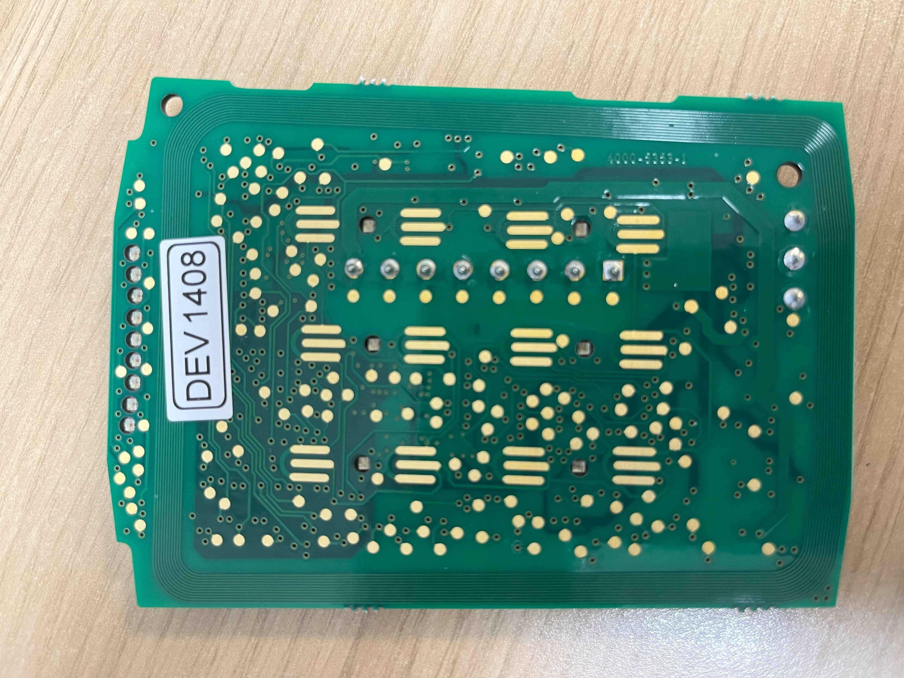
OE5S842Contactless smartcard reader with LCD and Keypad
G4S Technology Limited
Click to zoom
Application Details
- Equipment Class
- DXX - Part 15 Low Power Communication Device Transmitter
- Date of Grant
- Feb 12, 2004
- Application Purpose
- Original Equipment
- Date of Application
- Feb 10, 2004
- Equipment Note
- Contactless smartcard reader with LCD and Keypad
- Frequency Range
- 13.55300000 - 13.56700000
- Company
- G4S Technology Limited
- Country
- United Kingdom
Documents & Files
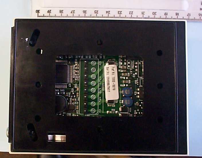
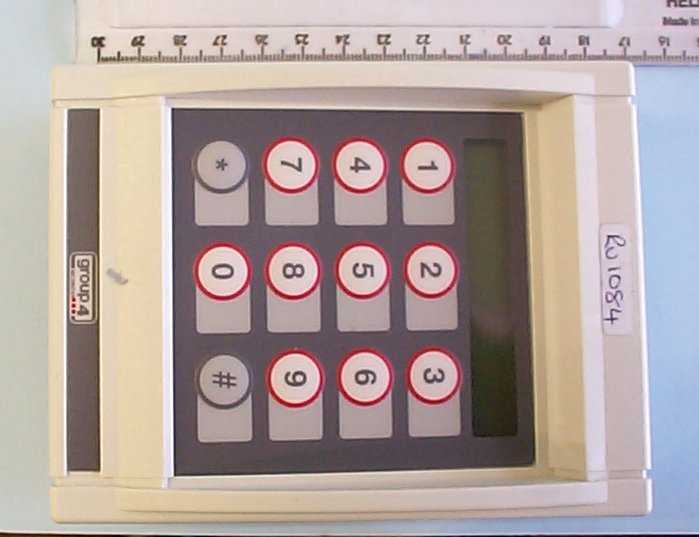
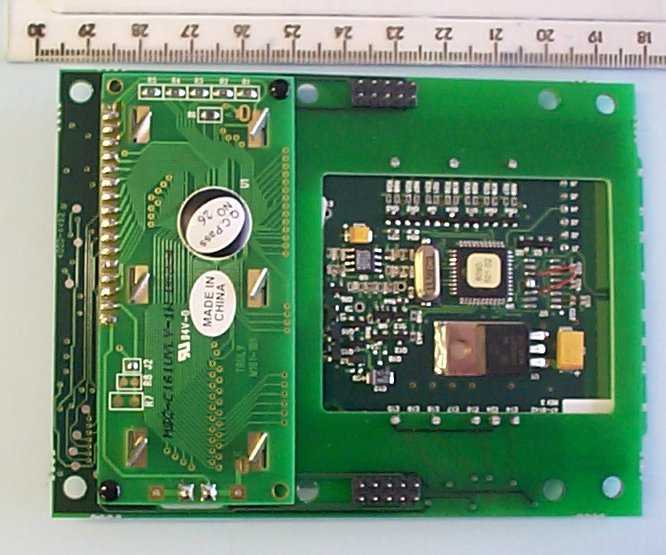
Document Text
Text extracted from the exhibit documents filed with the FCC. Open a document above to read the original.
Users Manual
Installation and User Instructions for S842 Readers You should find that the backplate has holes for connection to most standard electrical backboxes. With the backplate off (see above), mount the backplate adjacent to the opening edge of the door and at a convenient height. Feed the required cables through the backplate: The cable from the controller. The cable from the heater, if used (must be a separate cable). A cable from a Remote Interface Module (RIM), if used. A RIM can reduce cable lengths to door furniture. ! ! ! 2 The optional heater kit maintains the reader at the correct temperature when mounted outside. With the backplate off, remove the backing paper from the two elements, then stick them to the inner sides of the reader. The heaters must be connected to a 24V AC supply (min 25VA). When mounting outside, the two-part gasket kit must be fitted: a) Remove the backplate from the reader by releasing the two securing screws. b) Remove the cutouts and backing paper from the two gaskets, then stick them to the backplate as shown. Outer gasket Inner gasket Backplate securing screws Backplate 1 Fit the Weatherproofing Kit Mount the Backplate Ensure no jumpers are fitted across LK1 (TERM) and LK2 (TEST). If a jumper is provided, park it across one pin only. LK3 (USER FB) - set to 1 for sound on and 0 for sound off. 3 Reader Links The S842 is a contactless smart-card reader, with LCD and keypad, which usesp . The S842 is able to read HID i smart cards and the card serial number on Philips MIFARE smart cards. For either type of card, the S842 supports the use of unencoded cards (where only the unique card serial number is read). In the case of HID icards, an encoded card number can be read. Encoding formats supported include HID's own formats and the "smartMAX" format. CLASS CLASS TM 20mA current loop seudo-random communications ® ®® Present the card face-on to the reader until you hear a "bleep". Cards can be presented in rapid succession; there is no need, for example, to wait for UNLOCKED" toefore presenting another. "disappear b If the reader has been enabled for user-code mode at the controller, you can gain access by pressing the # key, entering your card number, then pressing the * key. Specifications Input voltage: 9-14Vdc. Input current (excl. heater): 150mA @ nom. 12Vdc. Operating temperature: -4 to 158 F (-20 to 70 C) without heater. Operating humidity: 15 to 90%, non-condensing. Maximum read range: 2.5" (65mm). Approvals: EN50133, R&TTE, IP656. °° 6 Using the Reader 0V Connect shield at controller end only (attach to case). RX+ RX- TX+ TX- 12V Reader Twisted pairs (use Belden 9503 cable) Controller connections (20mA current loop) The I/O terminal is for connection to a RIM (see the RIM Instructions). On completion, re-secure the reader to the backplate. 0V TX+ Do not use TX- I/0 RX+ RX- +V 4 Reader Connections A reader Setup menu can be displayed by pressing the * and # keys simultaneously while power is applied. You can use the menu to change the contrast and language used for the LCD (default English). At the prompts, press * for No and # for Yes. 5 Reader Configuration 9600-0343.Installation and User Instructions for S842 Readers, Issue 1.0x4 2nd December 2003.AMAG Technology Ltd, 2003. HID is a registered trademark of HID Corporation. iis a trademark of HID Corporation. Philips and MIFARE are registered trademarks of Philips Electronics N.V. FCC Notice:This device complies with Part 15 of the FCC Rules. Operation is subject to the following two conditions: (1) This device may not cause harmful interference, and (2) this device must accept any interference received, including interference that may cause undesired operation. Any unauthorized modification to this device may void the authority of the user to operate it. CLASS © About the Reader Messages } READY UNLOCKED ACCESS DENIED & LOCKED ENTER PIN – – The lock is released and you may open the door. – You do not have access rights to gain entry, or the reader did not read your card properly (in this case, present it again). – Enter your PIN. If you make a mistake, the message INCORRECT PIN is momentarily displayed, followed by ENTER PIN, to prompt you to try again. The reader is waiting for a valid card to be presented. (Flashing or steady)– These auxiliary indicators can be configured to operate in conjunction with conditional commands.
Cover Letter(s)
www.HIDCorp.com 9292 Jeronimo Road • Irvine, CA 92618-1905 • Phone (949) 598-1600 Fax (949) 598-1680 (Administration) • Fax (949) 598-1690 (Customer Service) • Fax (949) 598-1692 (Manufacturing & Purchasing) An ASSA ABLOY Group company February 10, 2004 TRL Compliance Services Ltd. TRL EMC Forthampton Glorcester GL 19 4QH United Kingdom 0.459 Request that submitted material be withheld from Public Inspection Products:31xxA (609x-301) iCLASS OEM Module Family It is requested that the following material be withheld from public inspection: Description of the iCLASS OEM Module, Circuit Functions, how the device operates, Ground System, and Antenna Block Diagram Schematic These materials are considered HID Corporation Proprietary and Confidential. Revealing the fundamental design for the product to the public, the OEM, and our competition would put us at a competitive disadvantage. We feel we have a product cost/design advantage over our competition with our iCLASS OEM Module family and therefore ask that the above-specified materials be withheld from public and OEM inspection. Frank de Vall Sr. Engineering Manager - Compliance Assa Abloy ITG & HID Corporation Assa Abloy ITG Research Center 11674 N. Huron Street Denver, CO 80234 USA
ID Label/Location Info
S842 HID iClass Proximity Reader Labels Product Label ( for S842 reader variant ) v FCC Label Issue 1 22-12-03 FCC ID OE5S842 Group 4 Technology Ltd. Type: S842 Model: 8000-5890-A Serial No: 9840006 9-14V DC 120mA
Test Report
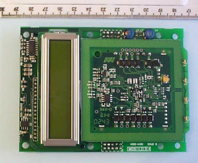
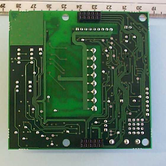
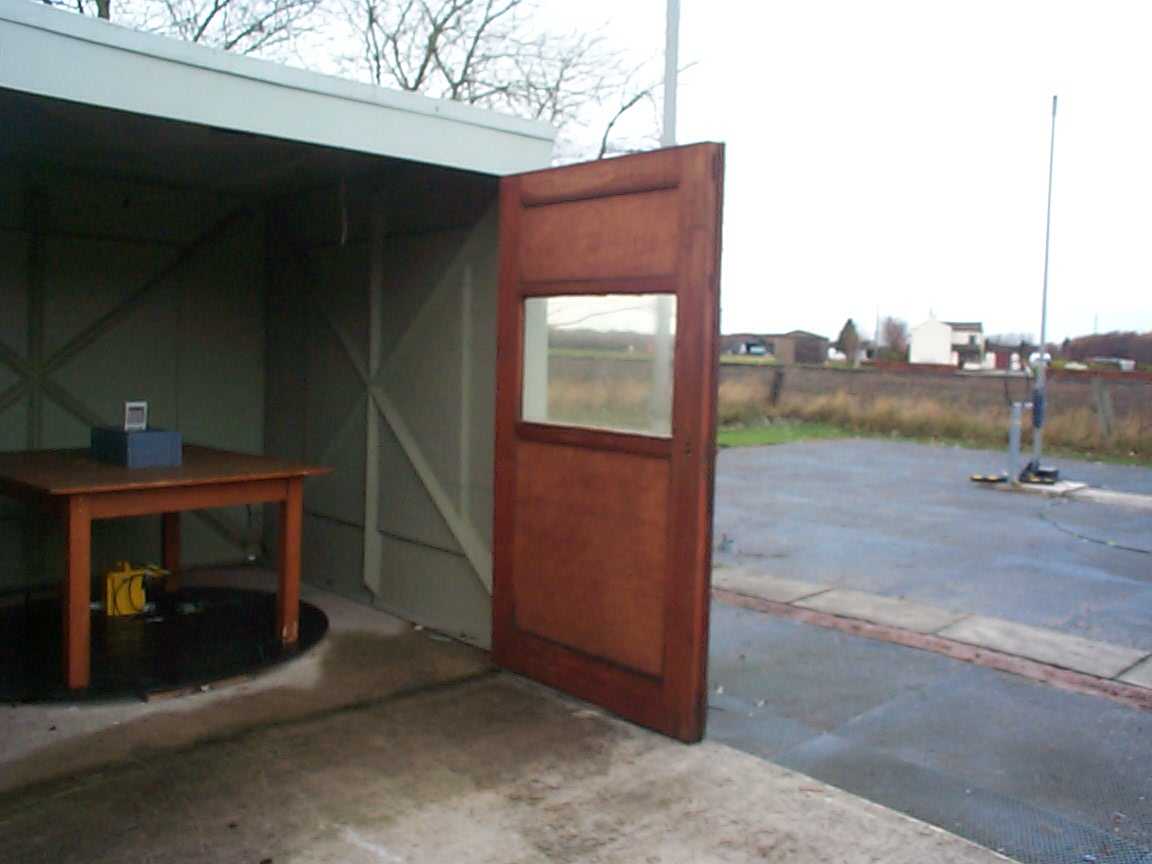
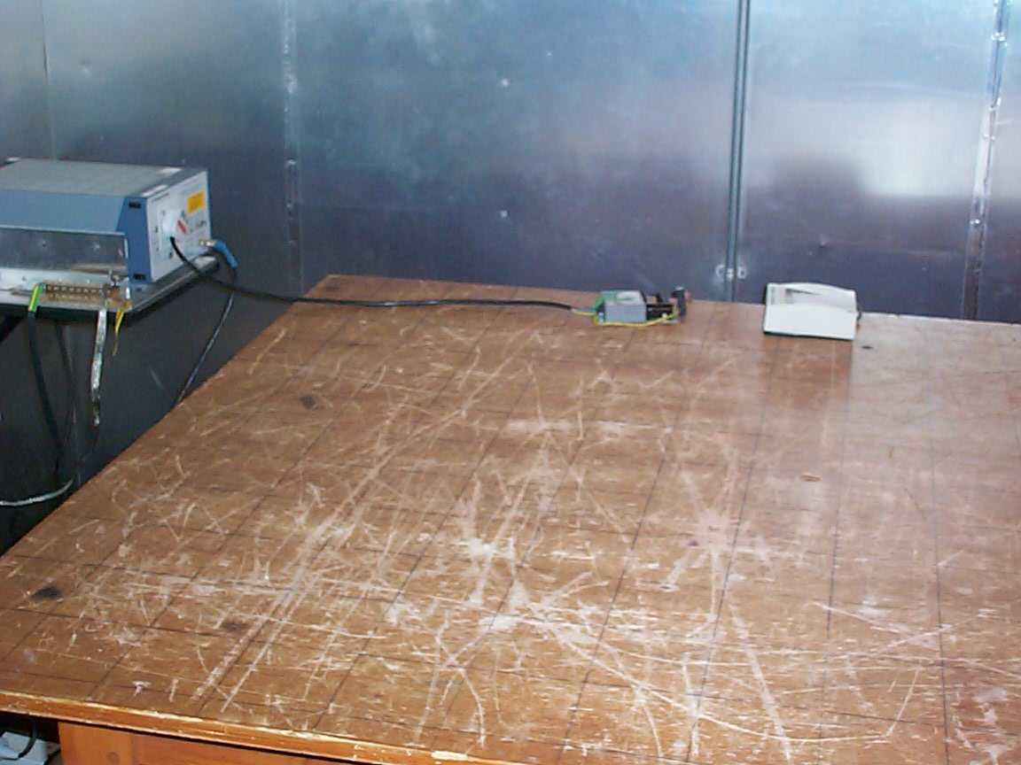
TRL COMPLIANCE SERVICES LTD EMC DIVISION MOSS VIEW NIPE LANE UP HOLLAND WEST LANCASHIRE WN8 9PY UNITED KINGDOM TELEPHONE +44 (0)1695 556666 FAX +44 (0)1695 557077 E-MAIL [email protected] www.trlcompliance.com 0728 FS 21805 TEST REPORT NO:RU1084/5151 COPY NO:2 ISSUE NO:1 FCC ID:OE5S842 REPORT ON THE CERTIFICATION TESTING OF A GROUP 4 TECHNOLOGY Ltd. S842 WITH RESPECT TO THE FCC RULES CFR 47, PART 15.225 INTENTIONAL RADIATOR SPECIFICATION TEST DATE: 18 th – 28 th NOVEMBER 2003 TESTED BY:J CHARTERS APPROVED BY:P GREEN EMC PRODUCT MANAGER DATE:5 th January 2004 Distribution: Copy Nos:1.GROUP 4 TECHNOLOGY Ltd. 2.FCC EVALUATION LABORATORIES 3.TRL EMC THIS DOCUMENT MAY BE REPRODUCED ONLY IN ITS ENTIRETY AND WITHOUT CHANGE RF335U iss03RU1084/5151Page 2 of 30 CONTENTS PAGE CERTIFICATE OF CONFORMITY & COMPLIANCE3 APPLICANT’S SUMMARY4 EQUIPMENT TEST CONDITIONS5 TESTS REQUIRED5 TEST RESULTS6-14 ANNEX PHOTOGRAPHSA PHOTOGRAPH No. 1: Test setup PHOTOGRAPH No. 2: Transmitter front view PHOTOGRAPH No. 3: Transmitter rear view PHOTOGRAPH No. 4: Transmitter PCB track side PHOTOGRAPH No. 5: Transmitter PCB component side PHOTOGRAPH No. 6: Antenna PCB component side PHOTOGRAPH No. 7: Antenna PCB track side PHOTOGRAPH No. 8: Test setup APPLICANT’S SUBMISSION OF DOCUMENTATION LISTB BAND OCCUPANCY PLOTC SCAN DATAD Notes: 1.Component failure during testYES NO [ ] [X] 2.If Yes, details of failure: 3.The facilities used for the testing of the product contain in this report are FCC Listed. 4.The contents of the attached applicants declarations and other supplied information are not covered by the scope of this laboratory’s UKAS or FCC accreditations’ and is provided in good faith. RF335U iss03RU1084/5151Page 3 of 30 CERTIFICATE OF CONFORMITY & COMPLIANCE FCC IDENTITY:OE5S842 PURPOSE OF TEST:Certification TEST SPECIFICATION:FCC RULES CFR 47, Part 15.225 TEST RESULT:Compliant to Specification EQUIPMENT UNDER TEST:S842 EQUIPMENT SERIAL No:0343357307 ITU: EMISSION CODE:12K0A1D EQUIPMENT TYPE:S842 Tag reader PRODUCT USE:Access and control CARRIER EMISSION: 63.97μV/m @ 30m ANTENNA TYPE:Integral ALTERNATIVE ANTENNA:Not applicable BAND OF OPERATION:13.553MHz –13.567MHz CHANNEL SPACING:N/A wideband NUMBER OF CHANNELS:1 FREQUENCY GENERATION:SAW Resonator[ ]Crystal[X]Synthesiser [ ] MODULATION METHOD:Amplitude[X]Digital[ ]Angle [ ] POWER SOURCE(s):12Vdc TEST DATE(s):18 th – 28 th NOVEMBER 2003 ORDER No(s):PRP10114 APPLICANT:GROUP 4 TECHNOLOGY Ltd. ADDRESS:Challenge House Northway Lane Tewkesbury Gloucester GL19 4QH TESTED BY:J CHARTERS APPROVED BY:P GREEN EMC PRODUCT MANAGER RF335U iss03RU1084/5151Page 4 of 30 APPLICANT’S SUMMARY EQUIPMENT UNDER TEST (EUT):S842 EQUIPMENT TYPE:S842 Tag reader SERIAL NUMBER OF EUT:0343357307 PURPOSE OF TEST:Certification TEST SPECIFICATION(s):FCC RULES CFR 47, Part 15.225 TEST RESULT:COMPLIANTYes No [X] [ ] APPLICANT’S CATEGORY:MANUFACTURER IMPORTER DISTRIBUTOR TEST HOUSE AGENT [X] [ ] [ ] [ ] [ ] APPLICANT’S ORDER No(s):PRP10114 APPLICANT’S CONTACT PERSON(s):Mr E Porter E-mail address:[email protected] APPLICANT:GROUP 4 TECHNOLOGY Ltd. ADDRESS:Challenge House Northway Lane Tewkesbury Gloucester GL19 4QH TEL:+44 (0) 1684 850997 FAX:+44 (0) 1684 294845 MANUFACTURER:GROUP 4 TECHNOLOGY Ltd. EUT(s) COUNTRY OF ORIGIN:United Kingdom TEST LABORATORY:TRL EMC UKAS ACCREDITATION No:0728 TEST DATE(s)18 th - 28 th NOVEMBER 2003 TEST REPORT No:RU1084/5151 RF335U iss03RU1084/5151Page 5 of 30 EQUIPMENT TEST / EXAMINATIONS REQUIRED 1. TEST/EXAMINATIONRULE PARTDETECTORAPPLICABILITY Intentional Emission Frequency:15.225Quasi PeakYes Intentional Emission Field Strength:15.225Quasi PeakYes Intentional Emission Band Occupancy:15.225Quasi PeakYes Intentional Emission ERP (mW):N/A-No Spurious Emissions – Conducted:15.207 Quasi Peak Average Yes Spurious Emissions – Radiated <1000MHz:15.209Quasi PeakYes Spurious Emissions – Radiated >1000MHz:N/A-No Maximum Frequency of Search:15.33-Yes Antenna Arrangements Integral:15.203-Yes Antenna Arrangements External Connector:15.204-No Restricted Bands15.205-Yes Extrapolation Factor15.31(f)-Yes 2.Product Use:Access/control 3.Emission Designator:12K0A1D 4.Duty Cycle:<100% 5.Temperatures:Ambient (Tnom)13 o C 6.Supply Voltages:Vnom12Vdc Note: Vnom voltages are as stated above unless otherwise shown on the test report page Single channel[X] Two channel[ ] 8.Equipment Category: Multi-channel[ ] Narrowband[ ] Wideband[X] 9.Channel spacing: RF335U iss03RU1084/5151Page 6 of 30 TRANSMITTER TESTS TRANSMITTER SPURIOUS EMISSIONS – RADIATED – PART 15.209 Ambient temperature=13 o C(<1GHz)10m measurements <30MHz[X] Relative humidity=80% (<1GHz),3m measurements >1GHz[X] Conditions=Open Area Test Site (OATS)30m extrapolated from 10m[X] Supply voltage=12Vdc Channel number=1 FREQ. (MHz) MEAS. Rx. (dBμV) CABLE LOSS (dB) ANT FACT. (dB/m) FIELD STRENGTH (dBμV/m) EXTRAP. FACTOR (dB) FIELD STRENGTH (μV/m) LIMIT (μV/m) 1.705MHz-30MHz27.1237.6--37.619.088.430 30MHz- 88MHz 40.7 54.25 67.81 24.2 30.1 33.85 0.6 0.6 0.6 12.7 6.4 5.05 37.5 37.1 39.5 - - - 74.98 71.61 94.4 100 100 100 88MHz-216MHz108.528.00.811.240.0-100.0150 216MHz-960MHz- 960MHz-1GHz- 1GHz-5GHz- 1.705MHz to 30MHz 30μV/m@ 30m 30MHz to 88MHz100μV/m@ 3m 88MHz to 216MHz150μV/m@ 3m 216MHz to 960MHz200μV/m@ 3m 960MHz to 1GHz500μV/m@ 3m Limits 1GHz to 5GHz500μV/m@ 3m See next page for the notes and test methods: RF335U iss03RU1084/5151Page 7 of 30 Notes: 1Results quoted are extrapolated as indicated 2 Emissions were searched to: (x) 1000MHz inclusive, as per Part 15.33a 3Extrapolation factor 9.5dB from 1m to 3m, as per Part 15.31f 4Extrapolation factor 19.08dB from 10m to 30m, as per Part 15.31f 5Measurements >1GHz @ 1m as per Part 15.31f(1) 6Receiver detector >1GHz = CISPR, Quasi-Peak, 120kHz bandwidth 7Receiver detector >1GHz = Peak Hold, 1MHz resolution bandwidth 8New batteries used for battery powered products. 9Emissions 20db’s below the limit were not necessarily recorded. 10For emission below 30MHz the measuring receiver automaticall…
Text truncated - open the document above for the full version.
Contact Information
Applicant
ANDY WATTS(Mr)
Technical Contact
Group 4 Technology LimitedERIC PORTER
[email protected]+44 1684 850977
Challenge House, Northway Lane · Tewkesbury, Gloucestershire · United Kingdom
Test Firm
TRL EMC LimitedNeil Roche
Technical Specifications
| # | Rule Parts | Frequency Range | Power Output | Tolerance |
|---|---|---|---|---|
| 1 | 15C | 13.553 MHz - 13.567 MHz | - | 0.0100000000 % |
Other Applications from G4S Technology Limited
OE5S870C
Dec 22, 2025Proximity card reader with keypad for access control systems
Equipment Class
DCD - Part 15 Low Power Transmitter Below 1705 kHz
OE5S884C
Dec 22, 2025Access Control Keypad Reader 884 MKII
Equipment Class
DXX - Part 15 Low Power Communication Device Transmitter
OE5S874C
Dec 19, 2025Smartcard reader with keypad for access control systems 874 MKII
Equipment Class
DXX - Part 15 Low Power Communication Device Transmitter
OE5S884O
Jan 20, 2020S884O Proximity Reader
Equipment Class
DXX - Part 15 Low Power Communication Device Transmitter
OE5S680A
Nov 19, 2013S680 Proximity Card Reader
Equipment Class
DXX - Part 15 Low Power Communication Device Transmitter