OE5S843AS843A Inductive Reader
G4S Technology Limited
Click to zoom
Application Details
- Equipment Class
- DXX - Part 15 Low Power Communication Device Transmitter
- Date of Grant
- Apr 27, 2010
- Application Purpose
- Original Equipment
- Date of Application
- Apr 27, 2010
- Equipment Note
- S843A Inductive Reader
- Frequency Range
- 13.55000000 - 13.56000000
- Company
- G4S Technology Limited
- Country
- United Kingdom
Documents & Files
Document Text
Text extracted from the exhibit documents filed with the FCC. Open a document above to read the original.
Users Manual
Installation and User Instructions for S843 Readers You should find that the backplate has holes for connection to most standard electrical backboxes. With the backplate off (see above), mount the backplate adjacent to the opening edge of the door and at a convenient height. Feed the required cables through the backplate: !The cable from the controller. !The cable from the heater, if used (must be a separate cable). !A cable from a Remote Interface Module (RIM), if used. A RIM can reduce cable lengths to door furniture. The optional heater kit maintains the reader at the correct temperature when mounted outside. With the backplate off, remove the backing paper from the two elements, then stick them to the inner sides of the reader. The heaters must be connected to a 24V AC supply (min 25VA). When mounting outside, the two-part gasket kit must be fitted: a)Remove the backplate from the reader by releasing the two securing screws. b)Remove the cutouts and backing paper from the two gaskets, then stick them to the backplate as shown. Outer gasket Inner gasket Backplate securing screws Backplate Ensure no jumpers are fitted across LK3 (NODE TERM), LK4 (HGU TERM) and LK2 (TEST). If a jumper is provided, park it across one pin only. LK1 (USER FB) - set to 1 for sound on and 0 for sound off. The S843 is a keypad, which uses p . The S843 is able to read Philips MIFARE and Philips MIFARE DESfire smart cards. For either type of card, the S843 supports the use of unencoded cards (where only the unique card serial number is read), or cards encoded with a card number. Several encoding formats are supported. The reader can simultaneously support two different card types/formats (e.g. non-encoded MIFARE and smartMAX- encoded MIFARE DESfire, or non-encoded MIFARE and smartMAX-encoded MIFARE). The reader is automatically configured to accept the first two card types/formats presented. contactless smart-card reader, with LCD and 20mA current loop seudo-random ®® communications Fit the Weatherproofing Kit 1 Mount the Backplate 2 Reader Links 3 Using the Reader 6 Reader Configuration 5 Presentthe cardface-ontothereaderuntilyouhear a"bleep". Cardscanbepresentedinrapidsuccession; there is no need, for example, to wait for "UNLOCKED" to disappear before presenting another. If the reader has been enabled for user-code mode at the controller, you can gain access by pressing the # key, entering your card number, then pressing the * key. 9600-0539. Installation and User Instructions for S843 Readers, Issue 1.0 14th April 2010. G4S Technology Limited 2010. FCC Notice: This device complies with Part 15 of the FCC Rules. Operation is subject to the following two conditions: (1) This device may not cause harmful interference, and (2) this device must accept any interference received, including interference that may cause undesired operation. Any unauthorized modification to this device may void the authority of the user to operate it. This device complies with the provisions of European Directive 1999/5/EC. All trademarks acknowledged. Philips and MIFARE are registered trademarks of Philips Electronics N.V. © About the Reader Messages } READY – UNLOCKED – The lock is released and you may open the door. ACCESS DENIED & LOCKED – You do not have access rights to gain entry, or the reader did not read your card properly (in this case, present it again). ENTER PIN – Enter your PIN. If you make a mistake, the message INCORRECT PIN is momentarily displayed, followed by ENTER PIN, to prompt you to try again. CARD PIN AND # – Enter the DESfire card PIN, then press # if the PIN is less than 8 digits. The reader is waiting for a valid card to be presented. (Flashing or steady) – These auxiliary indicators can be configured to operate in conjunction with conditional commands. Specifications Input voltage: 10.2-14Vdc. Input current (excl. heater): 190mA @ nom. 12Vdc. Operating temperature: -4 to 158F (-20 to 70C) without heater. Operating humidity: 15 to 90%, non-condensing. Maximum read range: 1" (25mm). Approvals: EN50133, 1999/5/EC, IP65. °° 0V RX+ RX- TX+ TX- 12V Reader Controller connections (20mA current loop) The I/O terminal is for connection to a RIM (see the RIM Instructions). On completion, re-secure the reader to the backplate. 0V TX+ Do not use TX- I/0 RX+ RX- +V The reader supports the first two different card types/formats presented after power-up. For example, encoded MIFARE and encoded MIFARE DESfire (in this example, unencoded cards would not be recognized). The reader enters this configuration mode whenever power is re-applied. A reader Setup menu can be displayed by pressing the * and # keys simultaneously while power is applied. You can use the menu to change the contrast and language used for the LCD (default English), and view the two card types/formats previously programmed. At the prompts, press * for No and # for Yes. Reader Connections 4 Slide the ferrite sleeve onto cable before wiring terminal block. Ferrite to be placed 50mm (2") up cable and held in place with cable ties. Note: The FERRITE must be fitted! Connect shield at controller end only (attach to case). Twisted pairs (use Belden 9503 cable).
External Photos
Front Overview Rear Overview
ID Label/Location Info
Serial Label Position 91 mm 1 12 mm
Internal Photos
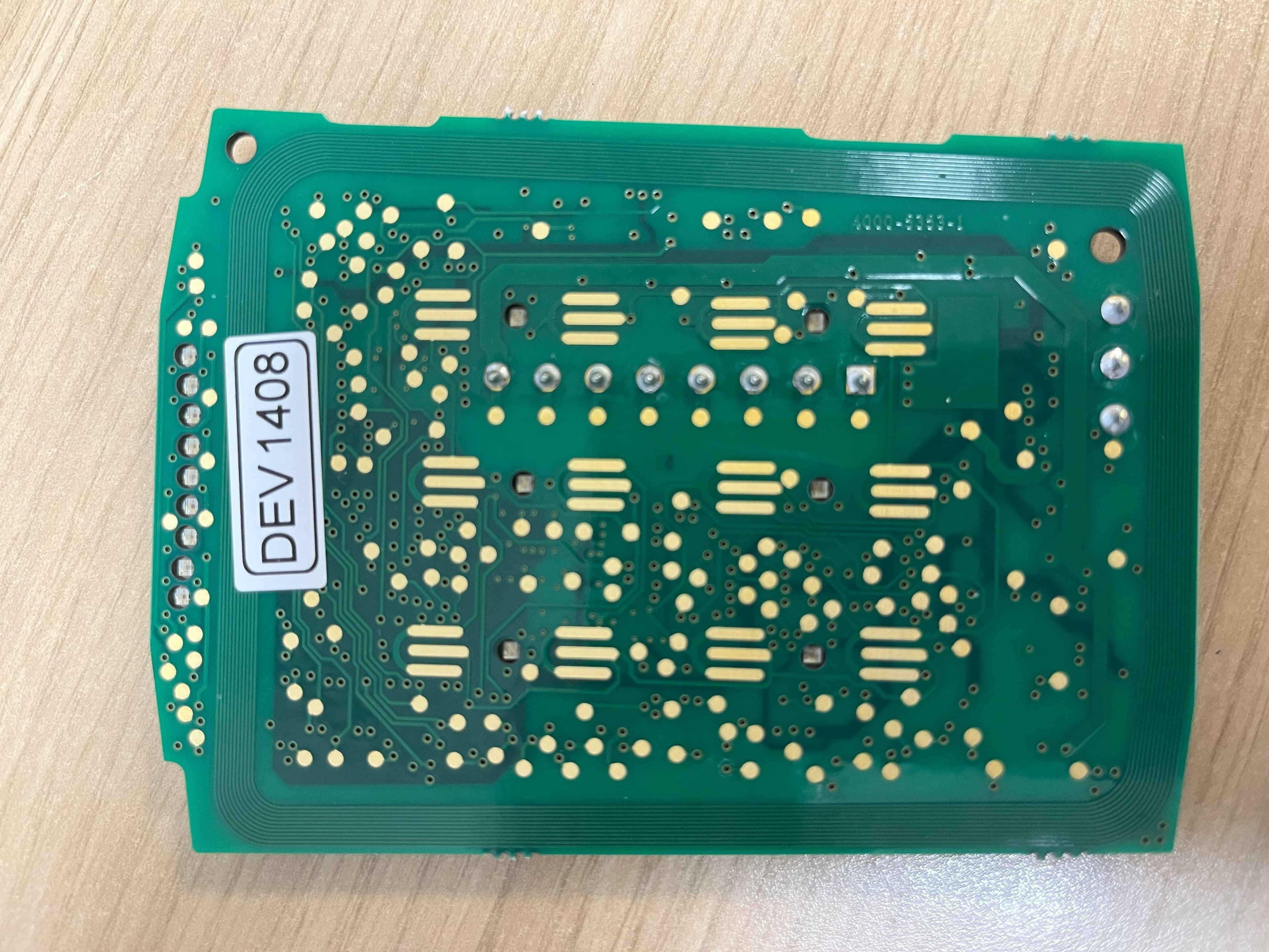
Main PCB Rear Side Main PCB Front Side Display PCB Antenna Mounted Display PCB Antenna Removed Rear Of Display PCB Antenna Front Overview Antenna Rear Overview
Test Report
Total number of pages: 37 TRaC Wireless Test Report:0F3107WUS1 Applicant:G4S Technology Limited Apparatus:S843 Specification(s):CFR47 Part 15 July 2008 Purpose of Test: Certification FCCID: OE5S843A Authorised by: : Radio Product Manager Issue Date:28 th April 2010 Authorised Copy Number: PDF RadioTest Report: 0F3107WUS1 2 Contents Section 1:Introduction3 1.1General3 1.2Tests Requested By4 1.3Manufacturer4 1.4Apparatus Assessed4 1.5Test Result Summary5 1.6Notes Relating To The Assessment6 1.7Deviations from Test Standards6 Section 2:Measurement Uncertainty7 2.1Application of Measurement Uncertainty7 2.2Measurement Uncertainty Values8 Section 3:Modifications10 3.1Modifications Performed During Assessment10 Appendix A:Formal Emission Test Results11 A1Transmitter Intentional Emission Radiated12 A2Radiated Electric Field Emissions13 A3Power Line Conducted Emissions15 A5Frequency Stability17 Appendix B:Supporting Graphical Data18 Appendix C: Additional Test and Sample Details24 Appendix D:Additional Information30 Appendix E:Calculation of the duty cycle correction factor31 Appendix F:Photographs and Figures32 Radio Test Report: 0F3107WUS1 3 Section 1:Introduction 1.1General This report contains an assessment of an apparatus against Electromagnetic Compatibility Standards based upon tests carried out on samples submitted to the Laboratory. Test performed by:TRaC Telecoms & Radio[ ] Unit E South Orbital Trading Park Hedon Road Hull, HU9 1NJ. United Kingdom. Telephone:+44 (0) 1482 801801 Fax:+44 (0) 1482 801806 TRaC Telecoms & Radio[X] Moss View Nipe Lane Up Holland West Lancashire, WN8 9PY United Kingdom Telephone:+44 (0) 1695 556666 Fax:+44 (0) 1695 577077 Email:[email protected] Web site:http://www.tracglobal.com Tests performed by:D Winstanley Report author:D Winstanley This report must not be reproduced except in full without prior written permission from TRaC Telecoms & Radio. Radio Test Report: 0F3107WUS1 4 1.2Tests Requested By This testing in this report was requested by : G4S Technology Limited Challenge House International Drive Tewkesbury Gloucestershire GL20 8UQ 1.3Manufacturer As Above 1.4Apparatus Assessed The following apparatus was assessed between 19/03/2010and 29/03/2010 S843 The above equipment is a 13.56MHzCard Reader Radio Test Report: 0F3107WUS1 5 1.5Test Result Summary Full details of test results are contained within Appendix A. The following table summarises the results of the assessment. The statements relating to compliance with the standards below apply ONLY as qualified in the notes and deviations stated in sections 1.6 to 1.7 of this test report. Full details of test results are contained within Appendix A. The following table summarises the results of the assessment. Test TypeRegulation Measurement standard Result Spurious Emissions Radiated <1000MHz Title 47 of the CFR: Part 15 Subpart (c) 15..209 ANSI C63.10Pass Spurious Emissions Radiated >1000MHz Title 47 of the CFR: Part 15 Subpart (c) 15.209 ANSI C63.10N/A AC Power conducted emissions Title 47 of the CFR: Part 15 Subpart (c) 15.207 ANSI C63.10Pass Intentional Emission Frequency Title 47 of the CFR: Part 15 Subpart (c) 15.225 ANSI C63.10Pass Intentional Emission Field Strength Title 47 of the CFR: Part 15 Subpart (c) 15.225 ANSI C63.10Pass Intentional Emission Band Occupancy Title 47 of the CFR: Part 15 Subpart (c) 15.2025 ANSI C63.10Pass Intentional Emission ERP (mW) Title 47 of the CFR: Part 15 Subpart (c) ANSI C63.10N/A Unintentional Radiated Spurious Emissions Title 47 of the CFR: Part 15 Subpart (b) 15.109 ANSI C63.10Pass Antenna Arrangements Integral: Title 47 of the CFR: Part 15 Subpart (c) 15.203 -Pass Antenna Arrangements External Connector Title 47 of the CFR: Part 15 Subpart (c) 15.204 -N/A Restricted Bands Title 47 of the CFR: Part 15 Subpart (c) 15.205 -- Maximum Frequency of Search Title 47 of the CFR: Part 15 Subpart (c) 15.33 -- Extrapolation Factor Title 47 of the CFR: Part 15 Subpart (c)15.31(f) -- Abbreviations used in the above table:- CFR: Code of Federal RegulationsANSI: American National Standards Institution REFE: Radiated Electric Field EmissionsPLCE: Power Line Conducted Emissions Radio Test Report: 0F3107WUS1 6 1.6Notes Relating To The Assessment With regard to this assessment, the following points should be noted: The results contained in this report relate only to the items tested and were obtained in the period between the date of initial receipt of samples and the date of issue of the report. The apparatus was set up and exercised using the configurations, modes of operation and arrangements defined in this report only. Particular operating modes, apparatus monitoring methods and performance criteria required by the standards tested to have been performed except where identified in Section 1.7 of this test report (Deviations from Test Standards). For emissions testing, throughout this test report, “Pass” indicates that the results for the sample as tested were below the specified limit (refer also to Section 2, Measurement Uncertainty). Where relevant, the apparatus was only assessed using the monitoring methods and susceptibility criteria defined in this report. All testing with the exception of testing at the Open Area Test Site was performed under the following environmental conditions: Temperature: 17 to 23 C Humidity : 45 to 75 % Barometric Pressure: 86 to 106 kPa All dates used in this report are in the format dd/mm/yy. This assessment has been performed in accordance with the requirements of ISO/IEC 17025. 1.7Deviations from Test Standards There were no deviations from the standards tested to. Radio Test Report: 0F3107WUS1 7 Section 2:Measurement Uncertainty 2.1Application of Measurement Uncertainty The following table contains the measurement uncertainties for measurements The following procedure is used when determining the result of a measurement : (i)If specification limits are not exceeded by the measured result, extended by the positive component of the expanded …
Text truncated - open the document above for the full version.
Test Setup Photos
H Field Test Setup Close Up AC Powerline Conduction
Contact Information
Applicant
ANDY WATTS(Mr)
Test Firm
Element Materials Technology Warwick LtdMax Leach
Technical Specifications
| # | Rule Parts | Frequency Range | Power Output |
|---|---|---|---|
| 1 | 15C | 13.55 MHz - 13.56 MHz | - |
Other Applications from G4S Technology Limited
OE5S870C
Dec 22, 2025Proximity card reader with keypad for access control systems
Equipment Class
DCD - Part 15 Low Power Transmitter Below 1705 kHz
OE5S884C
Dec 22, 2025Access Control Keypad Reader 884 MKII
Equipment Class
DXX - Part 15 Low Power Communication Device Transmitter
OE5S874C
Dec 19, 2025Smartcard reader with keypad for access control systems 874 MKII
Equipment Class
DXX - Part 15 Low Power Communication Device Transmitter
OE5S884O
Jan 20, 2020S884O Proximity Reader
Equipment Class
DXX - Part 15 Low Power Communication Device Transmitter
OE5S680A
Nov 19, 2013S680 Proximity Card Reader
Equipment Class
DXX - Part 15 Low Power Communication Device Transmitter