OE5S849S849 Inductive Reader
G4S Technology Limited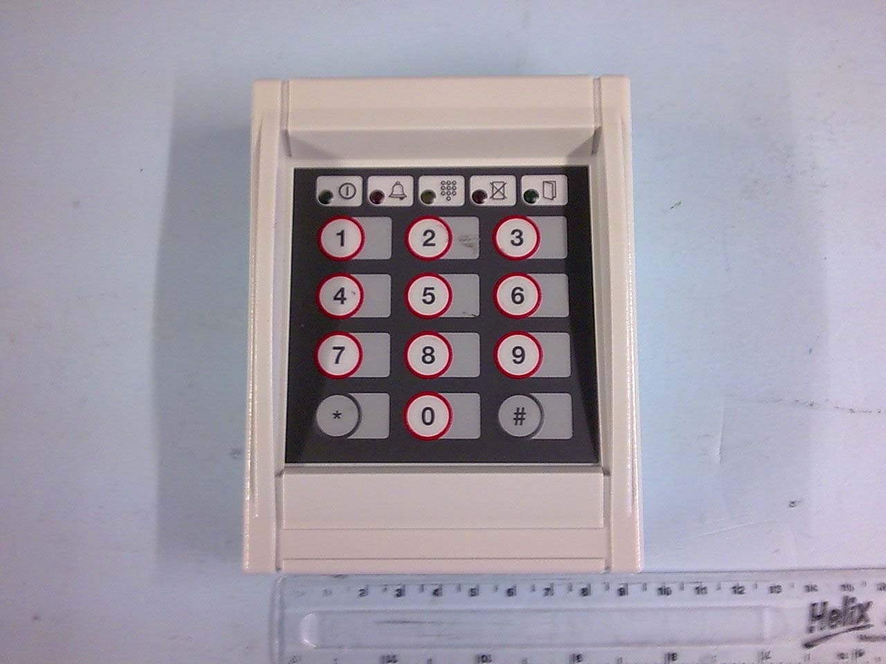
Click to zoom
Application Details
- Equipment Class
- DXX - Part 15 Low Power Communication Device Transmitter
- Date of Grant
- Dec 20, 2009
- Application Purpose
- Original Equipment
- Date of Application
- Dec 20, 2009
- Equipment Note
- S849 Inductive Reader
- Frequency Range
- 13.54000000 - 13.59000000
- Company
- G4S Technology Limited
- Country
- United Kingdom
Documents & Files
Document Text
Text extracted from the exhibit documents filed with the FCC. Open a document above to read the original.
Users Manual
Installation and User Instructions for S849 Readers You should find that the backplate has holes for connection to most standard electrical backboxes. With the backplate off (see above), mount the backplate adjacent to the opening edge of the door and at a convenient height. Feed the required cables through the backplate: The cable from the controller. The cable from the heater, if used (must be a separate cable). ! ! 2 The optional heater kit maintains the reader at the correct temperature when mounted outside. With the backplate off, remove the backing paper from the two elements, then stick them to the inner sides of the reader. The heaters must be connected to a 24V AC supply (min 25VA). When mounting outside, the two-part gasket kit must be fitted: a) Remove the backplate from the reader by releasing the two securing screws. b) Remove the cutouts and backing paper from the two gaskets, then stick them to the backplate as shown. Outer gasket Inner gasket Backplate securing screws Backplate 1 Fit the Weatherproofing Kit Mount the Backplate The S849 is a contactless smart-card reader with keypad. The S849 is able to read ISO14443 type A, Philips MIFARE Classic, MIFARE Ultra Light and MIFARE DESfire smart cards, and provides the option to use Wiegand or p For either type of card, the S848 supports the use of unencoded cards (where only the unique card serial number is read), or cards encoded with a card number. Several encoding formats are supported. The reader can simultaneously support two different card types/formats (e.g. non-encoded MIFARE and smartMAX- encoded MIFARE DESfire, or non-encoded MIFARE and smartMAX-encoded MIFARE). The reader is automatically configured to accept the first two card types/formats presented. ® ® 20mA current loop seudo-random communications. Specifications Input voltage: 10.2-14Vdc. Input current (excl. heater): 100mA @ nom. 12Vdc. Operating temperature: -13 to 158 F (-25 to 70 C) without heater. Operating humidity: 15 to 90%, non-condensing. Maximum read range: 5" (125mm). Approvals: EN300330, EN301489 °° 5 Using the Reader 4 Reader Connections 9600-0531.Installation and User Instructions for S849 Readers, Issue 1.0 16th Decemmber 2009.G4S Technology, 2009. All trademarks acknowledged. HID is a registered trademark of HID Corporation. FCC Notice:This device complies with Part 15 of the FCC Rules. Operation is subject to the following two conditions: (1) This device may not cause harmful interference, and (2) this device must accept any interference received, including interference that may cause undesired operation. Any unauthorized modification to this device may void the authority of the user to operate it. © Present the card face-on to the reader until you hear"bleep". Cards can be presented in rapid succession; there is no need to wait for the green or red LED to extinguish efore presenting another. a b If the reader has been enabled for user-code mode at the controller, you can gain access by pressing the # key, entering your card number, then pressing the * key. If the amber LED flashes, enter your PIN. If you make a mistake, the red LED is lit for a moment, then the flashing amber prompts you to try again. These auxiliary LED indicators can be configured to operate in conjunction with conditional commands. When this LED is lit, the lock is released and you may open the door. Green (access granted) LED Red (access denied) LED Flashing amber (PIN) LED Alarm LED Switch LED This is lit if you do not have access rights to gain entry, or if the reader could not read your card (in this case, move the card away, then present it again). About the Reader LEDs } Connect shield at controller end only (attach to case) TX- Reader Twisted pairs (use Belden) TX+ 0V TX- RX+ RX- +V Do not use Do not use Do not use Do not use 12Vdc TX+ RX+ RX- 0V Note:To configure the reader as a 20mA reader, connect the jumper across the center and "C/L" pins of LK1. WEC/L Current LoopReaderConnections 12Vdc Connect shield at controller end only (attach to case) Apply 0V to activate door- Green Red Data 0 Data 1 0V Reader Gn 0V 0s Do not use Do not +V Bz 1s Do not use Rd Note:To configure the reader as a Wiegand reader, connect the jumper across the center and "WE" pins of LK1. WEC/L Wiegand ReaderConnections
Attestation Statements
TRL 51F050 iss02B REQUEST FOR CONFIDENTIALITY I N ACCORDANCE WITH FCC RULE 0.459 16-12-2009 TRaC Global 100 Frobisher Business Park Leigh Sinton Road Malvern Worcestershire WR14 1BX UK RE: Certification Application FCC ID: OE5S849 To Whom It May Concern: Please be advised that the following information is to be held confidential on behalf of G4S Technology Limited. • Schematics • Parts Lists • Block Diagram The application contains technical information which G4S Technology Limited deems to be trade secrets and propriety. If made public, the information might be used to the disadvantage of the applicant in the market place. Thank you for your attention to this matter. Yours faithfully G4S Technology Limited Challenge House International Drive Tewkesbury Gloucestershire GL20 8UQ Howard Johnson Technical Director
External Photos
PHOTOGRAPHS
ID Label/Location Info
Serial Label Position 91 mm 1 12 mm
ID Label/Location Info
Rev: Comment: CN Number: Date: Init: Appr. Tolerance: Scale: 0100 1 st release of specification 16/12/09 APW EJP Unless otherwise stated: ISO-2768-F DO NOT SCALE Part name: Format: A4 Drawing number: Serial Label Portrait 23x51mm Wht 62200248 G4T/1028/05/08 Label Design Specification Symbol definition: Description: #i Item Number Item Number #M Model Model Number #S Serial Number Serial number in the format YYWWSSSSSSS (YY=year, WW=week number, SSSSSSS=serial number) prefixed with “S/N: “.Code 128 Barcode of Serial Number #V Voltage Input voltage #A Current Input Current #F FCC FCC Identifier Note: 1. Replace # codes with appropriate product data.. Material & Size definition: Description: #M Material Adhesive backed labels that are approved Underwriter Laboratory Recognized Marking and Labeling Systems (PGDQ2 or PGJI2). #C Colour White #H Height 51MM #L Length 23MM Text specifications: Description: Font All character and numbers must be written in Arial. Pre Defined must be in BOLD. Size The font must have an appropriate size. It must be easily readable without the need of magnifying utilities. Marking Method All required markings shall be silk screened, ink stamped, printed, molded or hot stamped Example of typical label:
Internal Photos
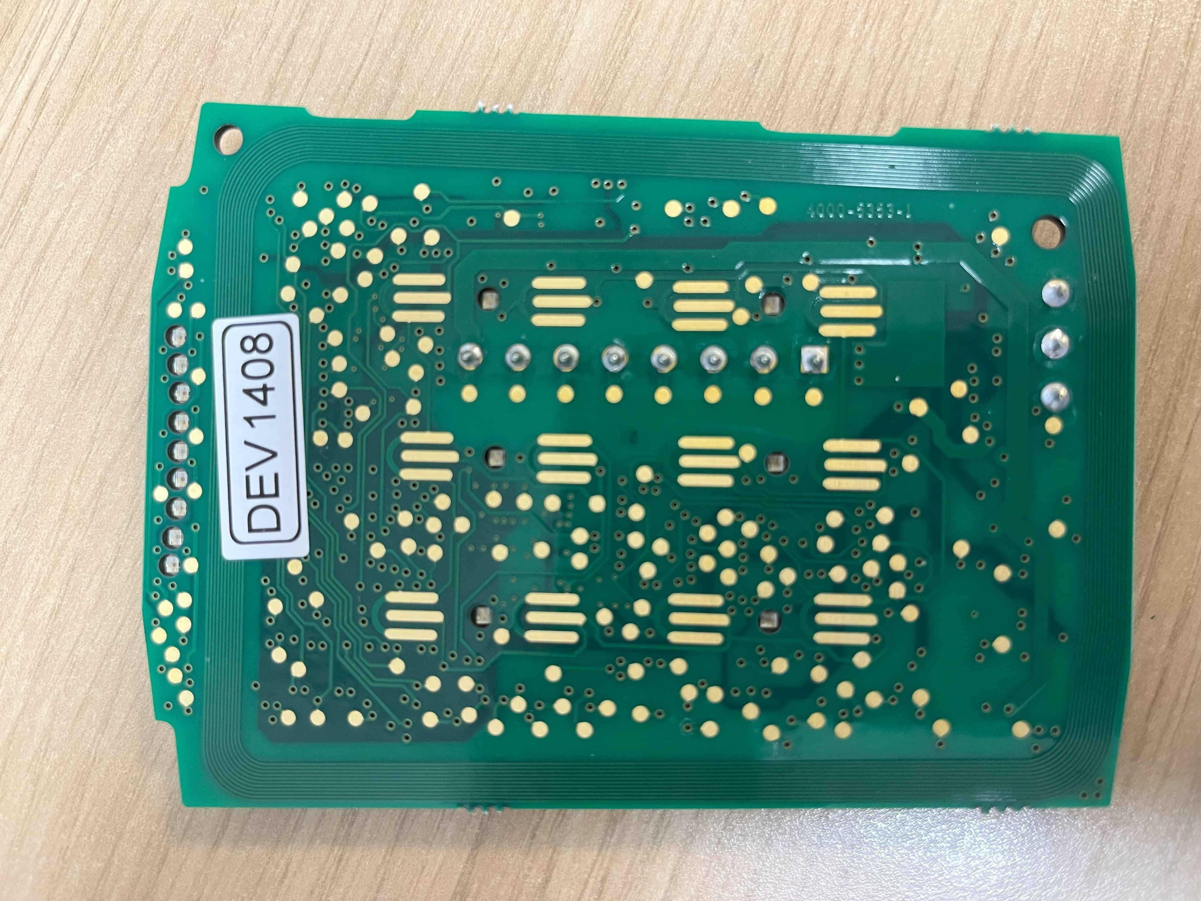
PHOTOGRAPHS
Test Report
REPORT ON THE CERTIFICATION TESTING OF A S849 CARD READER WITH RESPECT TO THE FCC RULES CFR 47, PART 15.225 JULY 2008 INTENTIONAL RADIATOR SPECIFICATION ON BEHALF OF GROUP 4 TECHNOLOGY Ltd TEST REPORT NO: 9F2776WUS1 COPY NO: 1 ISSUE NO: 1 FCC ID: OE5S849 REPORT ON THE CERTIFICATION TESTING OF A S849 CARD READER WITH RESPECT TO THE FCC RULES CFR 47, PART 15.225 JULY 2008 INTENTIONAL RADIATOR SPECIFICATION ON BEHALF OF GROUP 4 TECHNOLOGY Ltd TEST DATE: 13 th October - 29 th October 2009 TESTED BY: S HODGKINSON APPROVED BY: J CHARTERS PRODUCT MANAGER DATE: 24 th November 2009 Distribution: Copy Nos: 1. Group 4 Technology Ltd 2. FCC EVALUATION LABORATORIES 3. TRaC Telecoms and Radio THIS DOCUMENT MAY BE REPRODUCED ONLY IN ITS ENTIRETY AND WITHOUT CHANGE 9F2776WUS1 Page 3 of 35 CONTENTS PAGE CERTIFICATE OF CONFORMITY & COMPLIANCE 4 APPLICANT’S SUMMARY 5 EQUIPMENT TEST CONDITIONS 6 TEST RESULTS 7-12 ANNEX PHOTOGRAPHS A PHOTOGRAPH No. 1: H Field test setup PHOTOGRAPH No. 2: AC powerline test setup PHOTOGRAPH No. 3: E Field test setup PHOTOGRAPH No. 4: Overview PHOTOGRAPH No. 5: Rear View PHOTOGRAPH No. 6: Top View PCB case removed PHOTOGRAPH No. 7: Rear View PCB case removed APPLICANT’S SUBMISSION OF DOCUMENTATION LIST B MEASUREMENT UNCERTAINTY C TEST EQUIPMENT CALIBRATION D EMISSIONS GRAPH(s) E POWERLINE CONDUCTION EMISSIONS GRAPH(s) F EMISSIONS MASK COMPLIANCE G Notes: 1. Component failure during test YES NO [ ] [X] 2. If Yes, details of failure: 3. The facilities used for the testing of the product contain in this report are FCC Listed. 4. The contents of the attached applicants declarations and other supplied information are not covered by the scope of this laboratory’s UKAS or FCC accreditations’ and is provided in good faith. CERTIFICATE OF CONFORMITY & COMPLIANCE 9F2776WUS1 FCC IDENTITY: OE5S849 PURPOSE OF TEST: Certification TEST SPECIFICATION: FCC RULES CFR 47, Part 15.225 July 2008 TEST RESULT: Compliant to Specification EQUIPMENT UNDER TEST: S849 EQUIPMENT TYPE: Inductive Reader PRODUCT USE: RFID CARRIER EMISSION: 56.98 μV/m @ 30m ANTENNA TYPE: Integral FREQUENCY OF OPERATION: 13.56 MHz CHANNEL SPACING: Not Applicable/ Wideband NUMBER OF CHANNELS: 1 FREQUENCY GENERATION: SAW Resonator [ ] Crystal [X] Synthesiser [ ] MODULATION METHOD: Amplitude [X] Digital [ ] Angle [ ] POWER SOURCE(s): +12.0Vdc TEST DATE(s): 13 th October - 29 th October 2009 ORDER No(s): APPLICANT: Group 4 Technology Ltd ADDRESS: Group 4 Technology Ltd Challenge House Northway Lane Tewkesbury Gloucester Gloucestershire GL20 8UQ TESTED BY: S HODGKINSON APPROVED BY: J CHARTERS PRODUCT MANAGER 9F2776WUS1 Page 5 of 35 APPLICANT’S SUMMARY EQUIPMENT UNDER TEST (EUT): S849 EQUIPMENT TYPE: Inductive Reader PURPOSE OF TEST: Certification TEST SPECIFICATION(s): FCC RULES CFR 47, Part 15.225 July 2009 TEST RESULT: COMPLIANT Yes No [X] [ ] APPLICANT’S CATEGORY: MANUFACTURER IMPORTER DISTRIBUTOR TEST HOUSE AGENT [X] [ ] [ ] [ ] [ ] APPLICANT’S ORDER No(s): EL5326 APPLICANT’S CONTACT PERSON(s): Mr E Porter E-mail address: [email protected] APPLICANT: Group 4 Technology Ltd ADDRESS: Group 4 Technology Ltd Challenge House Northway Lane Tewkesbury Gloucester Gloucestershire GL20 8UQ TEL: 01684 850977 FAX: 01684 294845 EUT(s) COUNTRY OF ORIGIN: United Kingdom TEST LABORATORY: TRaC Telecoms and Radio UKAS ACCREDITATION No: 0971 TEST DATE(s): 16 th November - 4 th December 2007 TEST REPORT No: 9F2776WUS1 9F2776WUS1 Page 6 of 35 EQUIPMENT TEST / EXAMINATIONS REQUIRED 1. TEST/EXAMINATION RULE PART DETECTOR APPLICABILITY Intentional Emission Frequency: 15.225(a) Quasi-Peak Yes Intentional Emission Field Strength: 15.225(a) Quasi-Peak Yes Intentional Emission Band Occupancy: 12.255(e) Peak Yes Intentional Emission ERP (mW): - - No Spurious Emissions – Conducted: 15.207 Quasi-Peak Average Yes Spurious Emissions – Radiated <1000MHz: 15.209 Quasi-Peak Yes Spurious Emissions – Radiated >1000MHz: 15.209 Average Yes Maximum Frequency of Search: 15.33 - Yes Antenna Arrangements Integral: 15.203 - Yes Antenna Arrangements External Connector: 15.204 - Yes Restricted Bands: 15.205 - Yes Extrapolation Factor: 15.31(f) - Yes 2. Product Use: RFID 3. Duty Cycle: <100 % 4. Temperatures: Ambient (Tnom) 16 o C 5. Supply Voltages: Vnom +12.0Vdc Note: Vnom voltages are as stated above unless otherwise shown on the test report page Single channel [X] Two channel [ ] 6. Equipment Category: Multi-channel [ ] Narrowband [ ] Wideband [X] 7. Channel spacing: 9F2776WUS1 Page 7 of 35 TRANSMITTER TESTS TRANSMITTER SPURIOUS EMISSIONS – RADIATED – PART 15.209 Ambient temperature = 16 o C(<1GHz) 3m measurements <1GHz [X] Relative humidity = 54% (<1GHz), 10m measurements <30MHz [X] Conditions = Open Area Test Site (OATS) 30m extrapolated from 10m [X] Supply voltage = +12Vdc Channel number = 1 FREQ. (MHz) MEAS. Rx. (dBμV) CABLE LOSS (dB) ANT FACT. (dB/m) FIELD STRENGTH (dBμV/m) EXTRAP. FACTOR (dB) FIELD STRENGTH (μV/m) LIMIT (μV/m) 0.009MHz - 0.490MHz No significant emissions Note 9 0.490MHz - 1.750MHz No significant emissions Note 9 1.705MHz - 30.0MHz No significant emissions Note 9 30MHz - 88MHz 40.70 54.25 67.85 81.40 13.70 29.45 31.30 28.50 1.20 1.45 1.60 1.80 12.50 6.60 5.10 7.10 27.40 37.50 38.00 37.40 N/A 23.44 74.98 79.43 74.13 100 88MHz - 216MHz 94.90 108.50 135.56 149.20 162.75 176.30 189.85 203.45 21.75 22.20 12.40 25.68 28.56 29.40 26.55 27.90 1.75 2.00 2.30 2.32 2.54 2.50 2.65 2.70 9.80 11.30 11.00 10.10 9.90 9.10 8.80 8.90 33.30 35.50 25.70 38.10 41.00 41.00 38.00 39.50 N/A 46.23 59.56 19.27 80.35 112.20 112.20 79.43 94.40 150 216MHz - 960MHz 217.00 244.10 271.25 298.35 311.95 26.77 15.45 22.10 16.45 19.80 2.83 3.05 3.50 3.85 3.90 8.50 11.50 12.50 13.10 13.60 38.10 30.00 38.10 33.40 37.30 N/A 80.35 31.62 80.35 46.77 73.28 200 960MHz - 1GHz No significant emissions N/A Note 9 1GHz - 5GHz No significant emissions N/A Note 9 0.009MHz to 0.490MHz 2400/F(kHz) @ 300m 0.490MHz to 1.705MHz 24000/F(kHz) @ 30m 1.705MHz to 30MHz 30μV/m @ 30m 30MHz to 88MHz 100μV/m…
Text truncated - open the document above for the full version.
Test Setup Photos
Test setup
Contact Information
Applicant
ANDY WATTS(Mr)
Test Firm
Element Materials Technology Warwick LtdStewart Barrowclough
Technical Specifications
| # | Rule Parts | Frequency Range | Power Output |
|---|---|---|---|
| 1 | 15C | 13.54 MHz - 13.59 MHz | - |
Other Applications from G4S Technology Limited
OE5S870C
Dec 22, 2025Proximity card reader with keypad for access control systems
Equipment Class
DCD - Part 15 Low Power Transmitter Below 1705 kHz
OE5S884C
Dec 22, 2025Access Control Keypad Reader 884 MKII
Equipment Class
DXX - Part 15 Low Power Communication Device Transmitter
OE5S874C
Dec 19, 2025Smartcard reader with keypad for access control systems 874 MKII
Equipment Class
DXX - Part 15 Low Power Communication Device Transmitter
OE5S884O
Jan 20, 2020S884O Proximity Reader
Equipment Class
DXX - Part 15 Low Power Communication Device Transmitter
OE5S680A
Nov 19, 2013S680 Proximity Card Reader
Equipment Class
DXX - Part 15 Low Power Communication Device Transmitter