OEW-AGBBCDMA2000 Wireless Basestation
ADC Telecommunications Inc.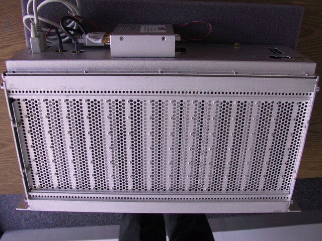
Click to zoom
Application Details
- Equipment Class
- AMP - Amplifier
- Date of Grant
- Feb 04, 2003
- Application Purpose
- Original Equipment
- Date of Application
- Feb 04, 2003
- Equipment Note
- CDMA2000 Wireless Basestation
- Frequency Range
- 1930.00000000 - 1990.00000000
- Company
- ADC Telecommunications Inc.
- Country
- United States
Documents & Files
Document Text
Text extracted from the exhibit documents filed with the FCC. Open a document above to read the original.
Users Manual
Interwave Wave2000 BSS Specification Printed 11/21/02 12:29 PM Interwave Wave2000 BSS Specification.docInterwave Proprietary Information 20 of 32 8. Manual The Microcell BSS is packaged in a standard 19 inch shelf, and can be integrated into the customers cabinet or cell site. The microcell RF subsystem may be configured per specific requirements of the application, or customer may choose to source this. The microcell BSS is intended for high capacity and flexible power output applications. It is designed to mount into standard 19 in telecom cabinets, and operates over temperature range of -20 to 50C. It has two receive connections per radio, for main and diversity reception. A single transmit connection per is used. The transmit output power at the radio is adjustable, but is in the 1 mW range. Radios are available for 800 MHz cellular (band 0) or 1900 MHz PCS (band 1) frequency operation. The microcell can support three sectors, with extra hardware to support redundancy. The microcell is designed to be cooled by an adjacent fan tray when operating above 40C. With fan tray, the microcell is designed to operate at a maximum of 50C ambient temperature. A fully populated microcell consists of the following cards: (2) Micro Power Supply Circuit Card (2) System Controller Circuit Card (2) System Timing Circuit Card (4) Channel Coder Circuit Card (4) Radio Modules (PCS or cellular frequency) (1) GPS receiver (mounted on rear of backplane) The microcell is powered by DC voltage, between 20 to 35V. Power consumption varies with number of cards, but a fully loaded microcell shelf consumes approximately 120W. Each card is packaged in protective metal shielding, both to protect cards from ESD damage during handling and prevent unwanted emissions from high speed circuitry. The exception is the micro power supply card, which needs air circulation for testing, and does not contain sensitive, high frequency circuitry. The system controller has multiple RF-45 interfaces. The upper two interfaces are currently unused, and reserved for future functionality. The third R-J45 is a 10BT Ethernet port, used for dedicated connection to network OA&M. It can also be used for diagnostic purposes during development. The lowest port is 100BT Ethernet, and is the main network connection, carrying both signaling and data. As these are local, short distance signaling, no high voltage protecting is needed or provided at these interfaces (as opposed to long haul E1/T1 signals, which may be subjected to high voltage surges). The system timing card has no front panel interfaces, but has several to rear via backplane. These are described under backplane interfaces. The channel card has no interfaces to the external world. It interfaces to a specific radio to the system controller card via the backplane. Interwave Wave2000 BSS Specification Printed 11/21/02 12:29 PM Interwave Wave2000 BSS Specification.docInterwave Proprietary Information 21 of 32 Each radio has 3 coax interfaces at the front panel. The upper and lower coax port are for dual receive inputs, while the center is for transmit. Each radio module is designed to support a specific frequency band. Current versions available support the 800 MHz (cellular) and 1900 MHz (PCS) bands. Each radio interfaces to a channel card via the backplane. The micro power supply card generates all voltages for the shelf, using the 20 to 35VDC input. The primary voltage used by all cards is 6.5VDC. The power supply also generates 12VDC for the GPS module, and 3.3 VDC as bias for Ethernet transformers on backplane. The backplane has 14 slots for the front mounted cards. Slots are keyed using card mounted grounding pins, to prevent improper insertion of card types. At rear of backplane are several connectors as follows: Microcell Power: 10 pin, requires voltage between 20 to 35 VDC. Diode protected against accidental reverse voltage. Microcell enable: 2 pin, when shorted together will enable microcell power supply. Will be disabled when open circuit. This is intended to connect to an external alarm control unit, which monitors ambient conditions to ensure microcell is operated only within recommended temperature and voltage ranges. Alarm Control Port: DB9 port for RS-232 connection to external alarm control unit. 2PPS: coax, used to output pulse per two seconds used for RF receiver measurement with external test equipment. GPS Port: DB9 port for RS-232 connection to GPS receiver. GPS Power: 2 pin, provides 12VDC for GPS unit. GPS 10M: coax, used to receive 10 MHz frequency reference from GPS unit. GPS 1PPS: coax, used to receive 1 pulse pre second signal from GPS unit. Interwave Wave2000 BSS Specification Printed 11/21/02 12:29 PM Interwave Wave2000 BSS Specification.docInterwave Proprietary Information 22 of 32 ALARM CONTROL UNIT + - GPS RS-232 GPS PWR 10MHz 1PPS GPS Receiver ACU RS-232 PP2S RACK ENABLE RACK POWER RS-232PWR +- +24VDC-24VDC FAN TRAY BTS RACK ANTENNA COMBINER UNIT MULTICARRIER AMPLIFIER POWER SUPPLY TEMPERATURE HUMIDITY SENSOR TO MPCA INPUT FROM MPCA OUTPUT MAIN ANT RF IN RF OUT DIV ANT + - 1 --- ALARMS -- 12 + + + + - - - - POSITIVE POWER RAIL (+) NEGATIVE POWER RAIL (-) ..... ..... ...... ...... . . AC POWER CONNECTOR I/O A .......... .......... .......... TERMINAL WIRING BOX I/O A GPS Antenna + - Fuse Figure 10 - An Example of a BSS Telecom Equipment Solution (Viewed from Back) Interwave Wave2000 BSS Specification Printed 11/21/02 12:29 PM Interwave Wave2000 BSS Specification.docInterwave Proprietary Information 23 of 32 8.1 5.3 System Configuration In the PC terminal, open two Hyper-terminals for COM 1 and COM 2 to monitor the SCON card and CHC card. Run a FTP server for uploading the application software into the SCON and CHC card. See details for setting up the FTP server in SCON or CHC testing documents. 1.1.1 5.3.1 Operating system configuration Firstly, configure the xvWorks operating system in both SCON and CHC cards in order to allow the PC terminal communica…
Text truncated - open the document above for the full version.
Block Diagram
Interwave Wave2000 BSS Specification Printed 11/21/02 12:29 PM Interwave Wave2000 BSS Specification.docInterwave Proprietary Information 15 of 32 SCON LAN or WAN BP GPS CHC 1 CHC 2 RFM 1 RFM 2 T R C S STIM 1 ACU PS CHC 3 CHC 4 (Redundancy) RFM 3 RFM (Redundancy) STIM 2 (Redundancy ) SCON (Redundancy) LAN or WAN MCPA and ACS M D MCPA and ACS M D MCPA and ACS M D Sector 1 Sector 2 Sector 2 Figure 9 - Base Station Structural Block Diagram 7.1 System Timing Unit Function (STIM Card) The STIM card provides all necessary clock and synchronization signals for overall system operation. These include timing for Channel Card, Radio A/D and D/A conversion, and RF subsystem and system time. It interfaces with external GPS receiver which provide a 10MHz and PPS (pulse per second) reference. When the GPS unit is present, the timing card synchronizes itself to the GPS. GPS is required to maintain system synchronization between different basestations. This synchronization is essential to allow soft handoff capability. Back plane communications interface to the card is over an InterWAVE proprietary bus. An RS-232 link is used to communicate between the STIM card and GPS unit. 7.2 Radio Module Function The Radio Module is composed of two cards: an RF card and a digitizing card. The RF card interface to air interface signals at selected frequency. The digitizing card provides an interface between the RF card and the digital base-band receive and transmit signals to the proprietary back plane buses. The Radio function performs up conversion of the transmit base-band signals to the RF signal, which can be send through to the antenna. In the receiver direction, down conversion is performed on RF signals main and diversity, which
ID Label/Location Info
Interwave Advanced Communications Model: Wave2000 BS Plus Input Voltage: 20-35VDC Ambient Operation Temperture: -20C MIN to +40C MAX With Forced Air Cooling, to +50C MAX FCC ID OEW-AGBB 3.000" 4.000" Mike Parker Manufactured by: If this label is to be put in a recess, request a Size Proof to insure a correct fit. Date Approved ____-_____-2002 by_________________________ Date the finished job is needed: _______ - _______ - 2002 Bradley Nameplate Corporation 48881 Kato Road Fremont CA 94539-8070 (510) 249-1350 FAX (510) 249-1440 www.bradleynp.com P/N : Company : Wave2000 BS Plus INTERWAVE Check: Spelling Layout Copy Fonts Please check carefully and sign approval (or request changes) Art Proof For: lk 11-6-02 BNP-AE-CPFRevB REV - White Mylar Matte Black none 100 Material: Lamination: Text color: Background: Quantity: Standard tolerance is +\- .010" unless otherwise agreed to. If this label is to be put in a recess, request a Size Proof to insure a correct fit. Technical drawings will be used for dimensional inspection only; All other inspection criteria is based upon this approved proof. green checked by fo 11-06-02 Company - PN rev - Color - Print order(if needed) - z# - Initials date Sqr Corners 4x R .125 4x Inverted for faxing See following page: Ø 100Quantity: Dimensions and Specifications per (company) Dwg# 7.5A MAX
Operational Description
Interwave Wave2000 BSS Specification Printed 11/21/02 12:29 PM Interwave Wave2000 BSS Specification.docInterwave Proprietary Information 13 of 32 6. Theory of Operation A CDMA Base Station System is an exptremely complex product. It is beyond the scope of the document to provide a comprehensive theory of operation. If more information is required regarding CDMA network and air interface design and implementation, it is recommended that several texts be consulted in this area. Two suggested references are: CDMA Systems Engineering Handbook, by Jhong Lee and Leonard Miller IS-95 CDMA and CDMA2000, by Vijay Garg The CDMA2000 standard documents are available online at: http://www.3gpp2.com/
Test Report
FCC CFR47 CERTIFICATION PART 22H and 24E TEST REPORT FOR CDMA2000 WIRELESS BASESTATION MODEL: WAVE2000 BS PLUS FCC ID: OEW-AGBB REPORT NUMBER: 02U1580-1 ISSUE DATE: OCTOBER 20, 2002 Prepared for INTERWAVE COMMUNICATIONS, INC. 312 CONSTITUTION DRIVE MENLO PARK, CA 94025 Prepared by COMPLIANCE CERTIFICATION SERVICES 561F MONTEREY ROAD, ROUTE 2 MORGAN HILL, CA 95037, USA TEL: (408) 463-0885 FAX: (408) 463-0888 REPORT NO: 02U1580-1 DATE: OCTOBER 20, 2002 FCC ID: OEW-AGBB EUT: CDMA2000 WIRELESS BASESTATION Page 2 of 49 COMPLIANCE CERTIFICATION SERVICES DOCUMENT NO: CCSUP4031A 561F MONTEREY ROAD, MORGAN HILL, CA 95037 USA TEL: (408) 463-0885 FAX: (408) 463-0888 This report shall not be reproduced except in full, without the written approval of CCS. This document may be altered or revised by Compliance Certification Services personnel only, and shall be noted in the revision section of the document. TABLE OF CONTENT 1. TEST RESULT CERTIFICATION.................................................................................................3 2. EUT DESCRIPTION.........................................................................................................................4 3. TEST METHODOLOGY..................................................................................................................4 4. TEST FACILITY...............................................................................................................................4 5. ACCREDITATION AND LISTING................................................................................................4 6. MEASURING INSTRUMENT CALIBRATION............................................................................4 7. APPLICABLE RULES......................................................................................................................5 8. TEST SETUP, PROCEDURE AND RESULT................................................................................7 8.1. SECTION 2.1046: RF POWER OUTPUT...................................................................................7 8.2. SECTION 2.1047: MODULATION CHARACTERISTICS.....................................................14 8.3. SECTION 2.1049: OCCUPIED BANDWIDTH........................................................................14 8.4. SECTION 2.1051: SPURIOUS EMISSION AT ANTENNA TERMINAL..............................21 8.5. SECTION 2.1053: FIELD STRENGTH OF SPURIOUS RADIATION...................................38 8.6 SECTION 2.1055: FREQUENCY STABILITY........................................................................43 8.7 CONDUCTED & RADIATED EMISSIONS: PART 15.207 & 15.209......................................46 9. ATTACHMENT...............................................................................................................................47 9.1. EUT SETUP PHOTOS...............................................................................................................47 9.2 EUT PHOTOGRAPHS...........................................................................................................49 9.3 INSTALLATION AND SERVICE MANUAL.........................................................................49 9.4 SCHEMATIC, PART LISTS AND BLOCK DIAGRAM.........................................................49 9.5 PROPOSED FCC ID LABEL FORMAT..................................................................................49 REPORT NO: 02U1580-1 DATE: OCTOBER 20, 2002 FCC ID: OEW-AGBB EUT: CDMA2000 WIRELESS BASESTATION Page 3 of 49 COMPLIANCE CERTIFICATION SERVICES DOCUMENT NO: CCSUP4031A 561F MONTEREY ROAD, MORGAN HILL, CA 95037 USA TEL: (408) 463-0885 FAX: (408) 463-0888 This report shall not be reproduced except in full, without the written approval of CCS. This document may be altered or revised by Compliance Certification Services personnel only, and shall be noted in the revision section of the document. 1. TEST RESULT CERTIFICATION COMPANY NAME: INTERWAVE COMMUNICATIONS, INC. 312 CONSTITUTION DRIVE MENLO PARK, CA 94025 CONTACT PERSON: RON ALLEN / PURCHASING MANAGER TELEPHONE NO: (650) 838-3208 EUT DESCRIPTION: CDMA2000 WIRELESS BASESTATION MODEL NAME: WAVE2000 BS PLUS BRAND NAME INTERWAVE COMMUNICATIONS DATE TESTED: OCTOBER 20, 2002 TYPE OF EQUIPMENT INTENTIONAL RADIATOR EQUIPMENT TYPE 824 – 869 MHz (22) & 1930-1990 MHz (24) Base Station MEASUREMENT PROCEDURE ANSI 63.4 / 1992, TIA/EIA 603 PROCEDURE CERTIFICATION FCC RULE CFR 47 PART 22 Subpart H and 24 Subpart E Compliance Certification Services, Inc. tested the above equipment for compliance with the requirement set forth in CFR 47, PART 22 Subpart H-Cellular Radiotelephone Service and 24 Subpart E-Broadband PCS. The equipment in the configuration described in this report, shows the measured emission levels emanating from the equipment do not exceed the specified limit. Note : This document reports conditions under which testing was conducted and results of tests performed. This document may not be altered or revised in any way unless done so by Compliance Certification Services and all revisions are duly noted in the revisions section. Any alteration of this document not carried out by Compliance Certification Services will constitute fraud and shall nullify the document. Test By: Released For CCS By: THU CHAN MICHAEL HECKROTTE SENIOR EMC ENGINEER CHIEF ENGINNER COMPLIANCE CERTIFICATION SERVICES COMPLIANCE CERTIFICATION SERVICES REPORT NO: 02U1580-1 DATE: OCTOBER 20, 2002 FCC ID: OEW-AGBB EUT: CDMA2000 WIRELESS BASESTATION Page 4 of 49 COMPLIANCE CERTIFICATION SERVICES DOCUMENT NO: CCSUP4031A 561F MONTEREY ROAD, MORGAN HILL, CA 95037 USA TEL: (408) 463-0885 FAX: (408) 463-0888 This report shall not be reproduced except in full, without the written approval of CCS. This document may be altered or revised by Compliance Certification Services personnel only, and shall be noted in the revision section of the document. 2. EUT DESCRIPTION The microcell BSS is intended for high capaci…
Text truncated - open the document above for the full version.
Test Setup Photos
REPORT NO: 02U1580-1 DATE: OCTOBER 20, 2002 FCC ID: OEW-AGBB EUT: CDMA2000 WIRELESS BASESTATION Page 47 of 49 COMPLIANCE CERTIFICATION SERVICES DOCUMENT NO: CCSUP4031A 561F MONTEREY ROAD, MORGAN HILL, CA 95037 USA TEL: (408) 463-0885 FAX: (408) 463-0888 This report shall not be reproduced except in full, without the written approval of CCS. This document may be altered or revised by Compliance Certification Services personnel only, and shall be noted in the revision section of the document. 9. ATTACHMENT 9.1. EUT SETUP PHOTOS CONDUCTED MEASUREMENT REPORT NO: 02U1580-1 DATE: OCTOBER 20, 2002 FCC ID: OEW-AGBB EUT: CDMA2000 WIRELESS BASESTATION Page 48 of 49 COMPLIANCE CERTIFICATION SERVICES DOCUMENT NO: CCSUP4031A 561F MONTEREY ROAD, MORGAN HILL, CA 95037 USA TEL: (408) 463-0885 FAX: (408) 463-0888 This report shall not be reproduced except in full, without the written approval of CCS. This document may be altered or revised by Compliance Certification Services personnel only, and shall be noted in the revision section of the document. RADIATED & SUBSTITUTION MEASUREMENTS
Contact Information
Applicant
Mark Miska(Director of Technology)
Test Firm
Compliance Certification Services IncSteve Cheng
Technical Specifications
| # | Rule Parts | Frequency Range | Power Output | Emission | Tolerance |
|---|---|---|---|---|---|
| 2 | 24 | 1.93 GHz - 1.99 GHz | 3.72 mW | F9W | 2.5 ppm |
Other Applications from ADC Telecommunications Inc.
OEWAKAD19
Oct 30, 2006GSM Base Station
Equipment Class
PCB - PCS Licensed Transmitter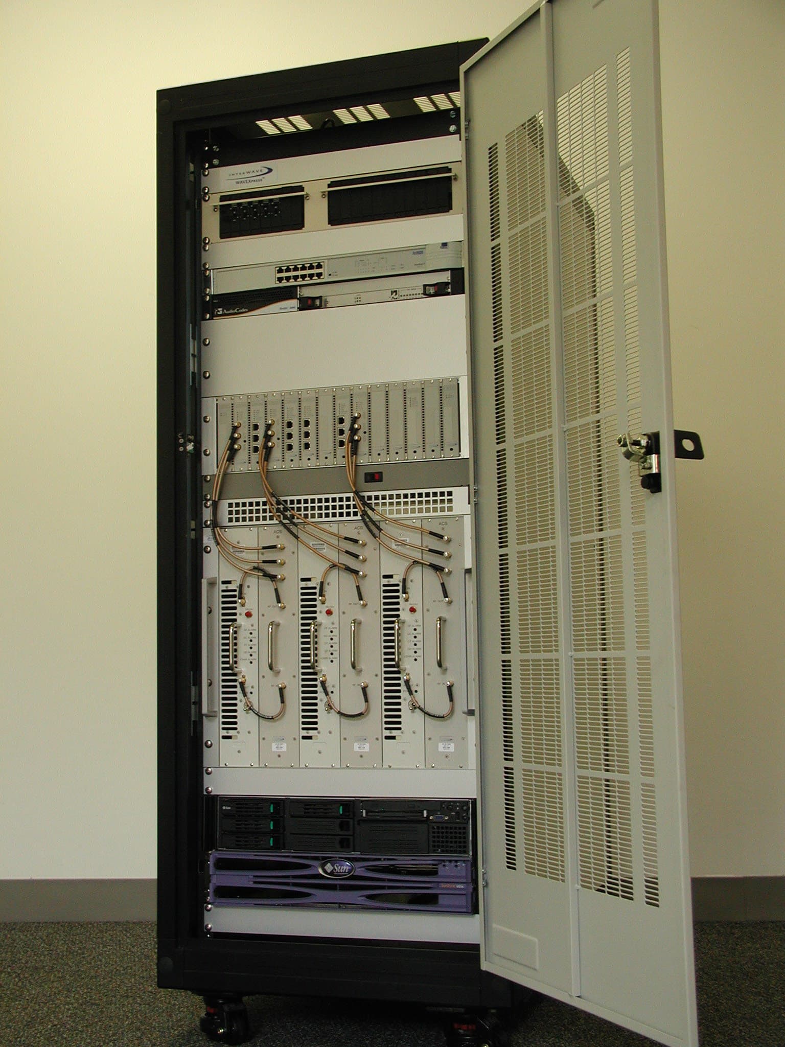
OEW-AGBB-M1
Dec 30, 2004CDMA Cellular BaseStation
Equipment Class
PCB - PCS Licensed Transmitter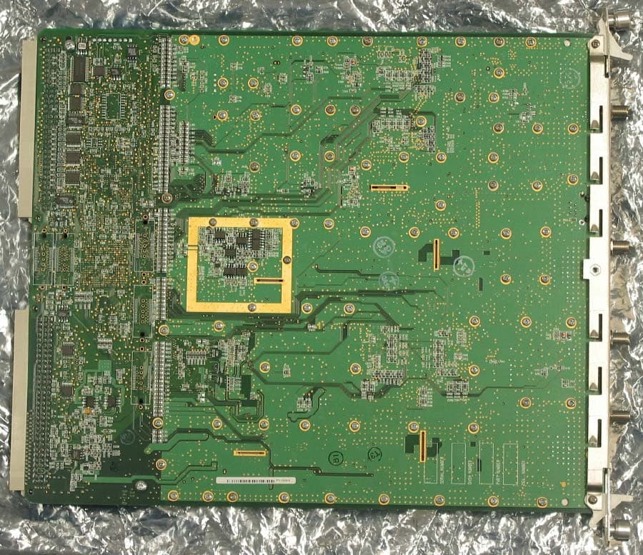
OEWAUAC85
Mar 03, 2003Ultra WAVE BTS
Equipment Class
TNB - Licensed Non-Broadcast Station Transmitter
OEWCX-DS3-53G
Jul 25, 2002Point to Point DSX3 / IP Transceiver
Equipment Class
NII - Unlicensed National Information Infrastructure TX
OEWCX-DS3-58G
Jul 24, 2002Point to Point DSX3 / IP Transceiver
Equipment Class
DTS - Digital Transmission System