OEWAKAD19GSM Base Station
ADC Telecommunications Inc.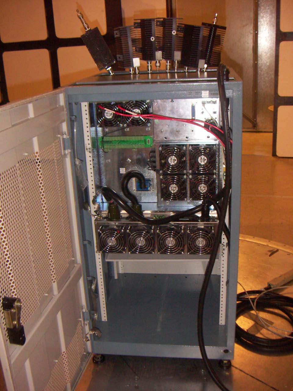
Click to zoom
Application Details
- Equipment Class
- PCB - PCS Licensed Transmitter
- Date of Grant
- Oct 30, 2006
- Application Purpose
- Original Equipment
- Date of Application
- Oct 30, 2006
- Equipment Note
- GSM Base Station
- Frequency Range
- 1930.20000000 - 1989.80000000
- Company
- ADC Telecommunications Inc.
- Country
- United States
Documents & Files
Document Text
Text extracted from the exhibit documents filed with the FCC. Open a document above to read the original.
Users Manual
Installation and Commissioning Guide SW Release 7.2 July 2006 P/N 214323 UltraWAVE Micro BTS iiUltraWAVE Micro BTS Installation and Commissioning Guide, Version B Legal Rights The material contained herein is proprietary, privileged, and confidential and owned by Alvarion or its third party licensors. No disclosure thereof shall be made to third parties without the express written permission of Alvarion Ltd. This document applies to the Alvarion release of the GSM or CDMA product lines and to all subsequent versions and releases of the hardware or software thereof unless otherwise indicated in a new version or an update package for the current edition dated November 2005. Publications requests should be addressed to your local sales support office. Alvarion Ltd. reserves the right to alter the equipment specifications and descriptions in this publication without prior notice. No part of this publication shall be deemed to be part of any contract or warranty unless specifically incorporated by reference into such contract or warranty. Use, duplication, or disclosure by the U.S. Government is subject to restrictions of FAR 52.227-14 (g) (2) (6/87) and FAR 52.227-19 (6/87), or DFAR 252.227-7015 (b) (6/95) and DFAR 227.7202-3 (a). The software described in this document is furnished under a license agreement. The software may be used or copied only in accordance with the terms of the agreement. It is a violation of Alvarion Ltd. proprietary rights to copy the software on any medium except as specifically allowed in the license agreement. The material contained herein is Alvarion proprietary, privileged, and confidential. No disclosure thereof shall be made to third parties without the express written permission of Alvarion. The information contained in this manual is subject to change without notice. Alvarion Ltd. shall not be liable for errors contained herein or for incidental or consequential damages in connection with the furnishing, performance, or use of this manual or equipment supplied with it. Alvarion's products are patented by one or more of the following United States Patents: No. 5,781,582, No. 5,682,403, No. 5,734,979, No. 5,734,699, No. 5,999,813, No. 5,953,651, No. 5,887,256, No. 5,577,029, No. 5,761,195, No. 5,842,138, No. 5,818,824, No. 5,957,464, No. 6,078,823, No. 6,070,071, No. 6,101,400, No. USP D 391,967, No. USP D 391,968, No. USP D 397,693. Trademark Acknowledgment Alvarion®, BreezeCOM®, WALKair®, WALKnet®, BreezeNET®, BreezeACCESS®, BreezeMANAGE™, BreezeLINK®, BreezeConfig™, BreezeMAX™, AlvariSTAR™, MGW™, eMGW™, WAVEXpress™, MicroXpress™, WAVEXchange™, WAVEView™, GSM Network in a Box and TurboWAVE™ and/or other products and/or services referenced here in are either registered trademarks, trademarks or service marks of Alvarion Ltd. All other names are or may be the trademarks of their respective owners. ©2006 Alvarion, Ltd. All Rights Reserved. United States Federal Communications Commission Required User Information Located on the equipment is a label that contains, among other information, the FCC registration number. If requested, this information must be provided to the telephone company. The UltraWAVE BTS Series AUAC series complies with Part 22 of the FCC Rules. UltraWAVE Micro BTS Installation and Commissioning Guide, Version Biii Legal Rights The 1900 MHz WAVEXpress Series M50 complies with Part 24 of the FCC Rules. The Breeze2000 BS Plus 800 MHz complies with Part 22 of the FCC Rules. The Breeze2000 Pico BS Plus (800 MHz and 1900 MHz) comply with Part 22 and Part 24 of the FCC Rules and UL 1950 safety certification. This equipment cannot be used on the telephone company-provided coin service. Connection to Party Line Service is subject to State Tariffs. If this equipment causes harm to the telephone network, the telephone company will notify you in advance that temporary discontinuance of service may be required. If advance notice isn’t practical, the telephone company will notify the customer as soon as possible. Also, you will be advised of your right to file a complaint with the FCC if you believe it is necessary. The telephone company may make changes in its facilities, equipment, operations, of procedures that could affect the operation of the equipment. If this happens, the telephone company will provide advance notice in order for you to make the necessary modifications in order to maintain uninterrupted service. If trouble is experienced with this equipment, please contact: Alvarion, Inc. 2495 Leghorn Drive Mountain View, CA 94043-1611 U.S.A. If the trouble is causing harm to the telephone network, the telephone company may request you to remove the equipment from the network until the problem is resolved. It is recommended that the customer install an AC surge arrester in the AC outlet to which that device is connected. This is to avoid damaging the equipment caused by local lightning strikes and other electrical surges. This equipment uses the following USOC jacks and codes: Note: This equipment has been tested and found to comply with the limits for a Class A digital device, pursuant to Part 15 of the FCC Rules. These limits are designed to provide reasonable protection against harmful interference when the equipment is operated in a commercial environment. This equipment generates, uses and can radiate radio frequency energy and, if not installed and used in accordance with the instruction manual, may cause harmful interference to radio communications. Operation of this equipment in a residential area is likely to USOC Jacks and Codes Model NameFacility Interface CodeService Order CodeJack Type 34012204DU9-BN6.ONRJ-48C 34012204DU9-DN6.ONRJ-48C 34012204DU9-1KN6.ONRJ-48C 34012204DU9-1SN6.ONRJ-48C 34012204DU9-1ZN6.ONRJ-48C ivUltraWAVE Micro BTS Installation and Commissioning Guide, Version B Legal Rights cause harmful interference in which case the user will be required to correct the interference at his own expense. Changes of modifications not ex…
Text truncated - open the document above for the full version.
Cover Letter(s)
Alvarion Inc. 2495 Leghorn St., Mountain View, CA 94043 Phone / Fax: +1.650.314.2500 / +1.650.967.3766 www.alvarion.com Date: September 25, 2006 Compliance Certification Services Certification Division 561F Monterey Road Morgan Hill, CA 95037 To whom it may concern: We, the undersigned, hereby authorize THOMAS N COKENIAS, d.b.a. T.N. Cokenias Consulting, to act on our behalf in all manners relating to application for equipment authorization through the Certification Division of Compliance Certification Services (CCS) , including signing of all documents relating to these matters. Any and all acts carried out by THOMAS N COKENIAS on our behalf shall have the same effect as acts of our own. We, the undersigned, hereby certify that we are not subject to a denial of federal benefits, that includes FCC benefits, pursuant to Section 5301 of the Anti-Drug Abuse Act of 1988, 21 U.S.C. 853(a). In authorizing THOMAS N COKENIAS as our agent, we still recognize that we are responsible to: a) comply with the relevant provisions of the certification program; b) make all necessary arrangements for the conduct of the evaluation, including provision for examining documentation and access to all areas, records (including internal audit reports) and personnel for the purposes of evaluation (e.g. testing, inspection, assessment, surveillance, reassessment) and resolution of complaints; c) make claims regarding certification only in respect of the scope for which certification has been granted; d) do not use our product certification in such a manner as to bring the Certification Division into disrepute and not make any statement regarding our product certification which the Certification Division may consider misleading or unauthorized; e) upon suspension or cancellation of certification, discontinue use of all advertising matter that contains any reference thereto and return any certification documents as required by the Certification Division;
Cover Letter(s)
tel: 650-726-1263 fax: 650-726-1252 [email protected] Thomas N. Cokenias EMC &Radio Approvals Test & Consulting Services for Commercial, Military, International Compliance P.O. Box 1086 El Granada, CA 94018 Compliance Certification Services 20 October 2006 561F Monterey Road Morgan Hill CA 95037 Attention: Application Examiner Reviewing Engineer RE: Request for confidentiality per FCC Rule Sections 0.457 and 0.459 Applicant: Alvarion Inc. 1900 MHz GSM Base Station FCC ID: OEWAKAD19 To whom it may concern, Request is hereby submitted, on behalf of my client Alvarion Inc. to withhold from public review indefinitely certain portions of the application for equipment certification for the referenced FCC identifier. In particular, the following sections of the application and report are requested to be kept confidential: Operational Description Schematic Block Diagram BOM/Parts List Rationale for request for confidentiality: Alvarion has invested considerable time and materials in research and development to produce the referenced product. Disclosure of the confidential portions of this application to competitors would give them competitive advantage in developing similar products. If you have questions or need further information, please contact the undersigned. Sincerely, THOMAS N. COKENIAS EMC Consultant/Agent for Alvarion Inc.
Cover Letter(s)
tel: 650-726-1263 fax: 650-726-1252 email [email protected] Thomas N. Cokenias EMC & Radio Type Approvals Test & Consulting Services for Commercial, Military, International Compliance P.O. Box 1086 El Granada, CA 94018 [email protected] Compliance Certification Services 24 October 2006 561F Monterey Road Morgan Hill CA 95037 Attention: Chris Harvey Re: Configuration of 1930-1990 MHz Part 24 BTS Applicant: Alvarion Inc. FCC ID: OEWAKAD19 Dear Mr. Harvey, This is to confirm the configuration of the EUT as it will be built and marketed, summarizing and consolidating information that is located in the document attachments submitted with this certification application. The EUT consists of a GSM radio transceiver card and RF power amplifier card with a 40 watt maximum RF output power, the pair making up one transceiver. The EUT is placed into an enclosure with card slots to accommodate up to 6 transceivers, and other slots to accommodate network interface cards. The enclosure also includes cooling fans and a power supply to power the transceivers and digital cards. Each transmitter has its own antenna port. The more typical configuration is 1-6 transmitters feeding their own antennas. Another configuration is two transmitter outputs connecting to a passive combiner which feeds a second antenna. Output power for this second configuration is 15 watts due to losses in the combiner circuit. The transmitter tests were performed with the EUT operating in the single radio mode, with 40watt output at antenna terminals. The cabinet was tested for unintentional radiated emissions for two different network card configurations, as well as for radiated emissions from the transmitter. The FCC ID label will be placed on the cabinet housing the EUT. It is understood that there may be as many as 6 identical EUTs inside the cabinet, and that the FCC ID refers to the transceiver/power amplifier combination. If you have questions or need further information, please don’t hesitate to call. Sincerely, T.N. Cokenias Agent for Alvarion inc.
External Photos
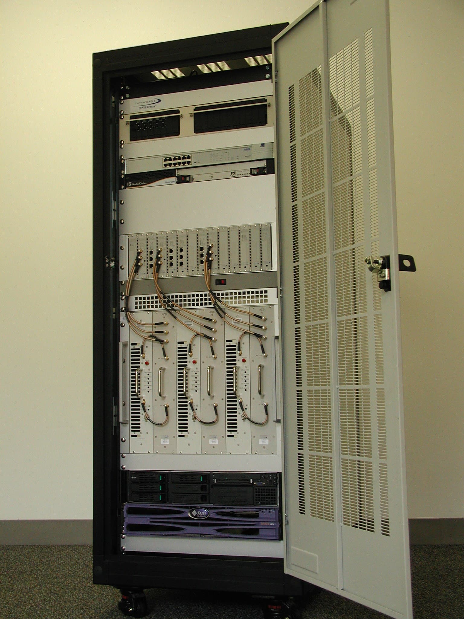
Alvarion Inc. FCC ID: OEWAKAD19 External Photos Front View Front view, door open Rear View Rear View, Door Open
ID Label/Location Info
A Sept 25 06 160138-00 Rev A 160138a-00.ai 160138a-00.ai 160138-00 FCC ID: OEWAKAD19
Internal Photos
Alvarion Inc. FCC ID: OEWAKAD19 RF module overview DSP board TRX Assembly, shield over board TRX board top TRX board bottom Combiner bottom Combiner top LNA bottom LNA top Splitter top Splitter bottom PA board
Parts List/Tune Up Info
Alvarion Inc. 2495 Leghorn St., Mountain View, CA 94043 Phone / Fax: +1.650.314.2566 / +1.650.967.3766 www.alvarion.com UltraWAVE Micro BTS/BSPlus/NIB Power Tune-up Procedure The information disclosed in this document is proprietary to Alvarion Inc., and is not to be used or disclosed to unauthorized persons without the written consent of Alvarion Inc. The recipient of this document shall respect the security of this document and maintain the confidentiality of the material. The master copy of this document is stored in electronic format, therefore any hard or soft copy used for distribution purposes must be considered as uncontrolled. Alvarion Inc. Confidential & Proprietary Page 1 of 1 1. Power Tune-up Procedure The output power of the UltraWAVE Micro BTS/BSPlus/NIB is controlled by the BTS system software. There is no hardware adjustment for output power setting. Under the normal operational condition, the maximum output power is automatically set to 40W(+46dBm) at the antenna port for all transmitter channels. When the system operator need to change the power setting at the BTS, change can be made through the software commands from the remote operation & control center or from the local Craft PC. The power level is controlled down to –12 dB (+35dBm) from the maximum power in 2 dB steps (6 levels). The output power level at the highest and lowest channel frequency (Channel #512: 1,930.2MHz and Channel #810: 1,989.8MHz) is automatically limited to 8W(+39 dBm) by the software in order to meet the FCC spurious requirement at the band edge frequencies (1,930.0MHz and 1,990.0MHz). This limitation only applies to these two channels and all other channels are set with nominal 40W(+46dBm). 2. Glossary BTS: Base Transceiver Station End of document
Test Report
Alvarion Inc. FCC ID: OEWAKAD19 Test Report No. 06PR046FCC Issued 21 October 2006 page 1 of 38 Alvarion Inc. 1930-1990 MHz GSM Base Station FCC ID: OEWAKAD19 Model No.: WAVEXpress M50 FCC Rule Parts: 2, 24 General Overview A description of the theory of operation and product configuration is found in an attachment to this application and report. SPECIFICATIONS Transmitter TX operating frequency: 1930.2 – 1989.8 MHz TX output power: 40 watts nominal, 47.3 watts measured Modulation: GSM (GMSK) Modulation is internally generated and limited Power requirements: 110VAC, 30 A/220VAC,15A/-48-60VDC, 40A Frequency Tolerance less than 0.001 ppm -30 to +50 C 85%-115% supply voltage at 25C Test Dates: 11, 14,15, 19, and 26 September 2006 Test Site Antenna port conducted tests and frequency stability tests were performed at the Alvarion test lab location in Mountain View, CA. Radiated spurious emissions, unintentional radiator emission, and AC line conducted tests were performed at Compliance Certification Services in Morgan Hill, CA. THOMAS N. COKENIAS Consultant, EMC&Radio Type Approvals Agent for Alvarion Inc. Alvarion Inc. FCC ID: OEWAKAD19 Test Report No. 06PR046FCC Issued 21 October 2006 page 2 of 38 FCC CERTIFICATION INFORMATION The following information is in accordance with FCC Rules, 47CFR Part 2. 2.1033(c)1 Applicant: Alvarion Inc. Inc. 2495 Leghorn St., Mountain View, CA 94043 2.1033(c)2 FCC ID: OEWAKAD19 2.1033(c)4,5 Emission type and Frequency range Modulation: GMSK from internal source Emission designator: 300KG1D 2.1033(c) 6 Range of Operating Power 40 watts peak (46.0 dBm) in single configuration 15 watts peak (41.76 dBm) in 2 transmitter combined configuration 2.1033(c) 7 Maximum Power Rating 46.75 dBm measured = 47.3 watts 2.1033(c) 13 Description of Modulation System GMSK per the GMS standard Alvarion Inc. FCC ID: OEWAKAD19 Test Report No. 06PR046FCC Issued 21 October 2006 page 3 of 38 2.1033(c) 14 Test Data per 2.1046 – 2.1057 DescriptionManufacturerModelSerial NumberCal Due EMI Receiver, 9 kHz ~ 2.9 GHzAgilent / HP8542E3942A002862/4/07 EMI Receiver, 9kHz - 30 MHzR&SESH 20827129/0066/1/07 Line impedance stabilization networkFCCLISN-50/250-25-27/15/058/20/07 RF Filter SectionAgilent / HP85420E3705A002562/4/07 Antenna, Bilog 30 MHz ~ 2 GhzSunol SciencesJB1A1210039/3/06 Spectrum analyzerHP8593EMCCS T327/26/08 Spectrum analyzer (Alvarion)HP8594E3346A007132/3/07 Spectrum analyzer (Alvarion)R&SFSEM849016/02210/11/06 Attenuator (Alvarion)Bird100-SA-MFN-30N/A3/3/07 Power meter (Alvarion)AgilentE4418BGB402051103/2/07 Power Sensor (Alvarion)AgilentE4413AUS371814893/2/07 Frequency counter (Alvarion)HP53181AKR912016117/6/07 External Frequency refeenceHP58503A3504A001337/6/07 TEST EQUIPMENT LIST Alvarion Inc. FCC ID: OEWAKAD19 Test Report No. 06PR046FCC Issued 21 October 2006 page 4 of 38 2.1046 RF Output Power Measurements Requirement/Limit: 24.232 a) Base stations are limited to 1640 watts peak equivalent isotropically radiated power (EIRP) with an antenna height up to 300 meters HAAT, except as described in paragraph (b) below. See §24.53 for HAAT calculation method. Base station antenna heights may exceed 300 meters with a corresponding reduction in power; see Table 1 of this section. The service area boundary limit and microwave protection criteria specified in §§24.236 and 24.237 apply. Table 1_Reduced Power for Base Station Antenna Heights Over 300 Meters ------------------------------------------------------------------------ Maximum HAAT in meters EIRP watts ------------------------------------------------------------------------ [le] 300................................................... 1640 [le] 500................................................... 1070 [le] 1000.................................................. 490 [le] 1500.................................................. 270 [le] 2000.................................................. 160 ------------------------------------------------------------------------ Test set-up: Figure 1 Test Procedures 1. Set the transmitter to produce maximum modulated power at the desired frequency 2. Read PEAK output power. Note: For GMSK modulation, a constant carrier modulation, Pave = Ppk Test Results Channel Number Frequency, MHz Pout, dBm 512 (low channel) 1930.2 39.02 513 (low ch max P) 1930.4 45.82 661 (mid channel) 1960 46.76 809 (high ch max P) 1989.6 46.48 810 (high channel) 1989.8 39.75 EUT software automatically limits output power to 39 dBm at Low and High channel to meet out of band emissions limits at band edge. 30 dB EUT Power sensor Laptop Computer Power Meter Alvarion Inc. FCC ID: OEWAKAD19 Test Report No. 06PR046FCC Issued 21 October 2006 page 5 of 38 Section 2.1047 Modulation Characteristics Section 2.1049 Occupied Bandwidth Requirement/Limit: 24.238 Emission limitations for Broadband PCS equipment (a) Out of band emissions. The power of any emission outside of the authorized operating frequency ranges must be attenuated below the transmitting power (P) by a factor of at least 43 + 10 log (P) dB. (b) Measurement procedure. Compliance with these rules is based on the use of measurement instrumentation employing a resolution bandwidth of 1 MHz or greater. However, in the 1 MHz bands immediately outside and adjacent to the frequency block a resolution bandwidth of at least one percent of the emission bandwidth of the fundamental emission of the transmitter may be employed. A narrower resolution bandwidth is permitted in all cases to improve measurement accuracy provided the measured power is integrated over the full required measurement bandwidth (i.e. 1 MHz or 1 percent of emission bandwidth, as specified). The emission bandwidth is defined as the width of the signal between two points, one below the carrier center frequency and one above the carrier center frequency, outside of which all emissions are attenuated at least 26 dB below the transmitter power. Test set-up: Figure 2 Ref level offset = cable loss + 30 dB = 31.9 dB Te…
Text truncated - open the document above for the full version.
Test Setup Photos
Alvarion Inc. FCC ID: OEWAKAD19 Test Set-up Photographs Radiated emissions, Front Vielw Rear View Antenna Port Conducted AC Line Conducted Section 15.107
Contact Information
Applicant
Mark Miska(Director of Technology)
Test Firm
Compliance Certification ServicesBarbara Judge
Technical Specifications
| # | Rule Parts | Frequency Range | Power Output | Emission | Tolerance |
|---|---|---|---|---|---|
| 1 | 24E | 1.93 GHz - 1.99 GHz | 47.3 W | 300KG1D | 0.0010000000 ppm |
Other Applications from ADC Telecommunications Inc.
OEW-AGBB-M1
Dec 30, 2004CDMA Cellular BaseStation
Equipment Class
PCB - PCS Licensed Transmitter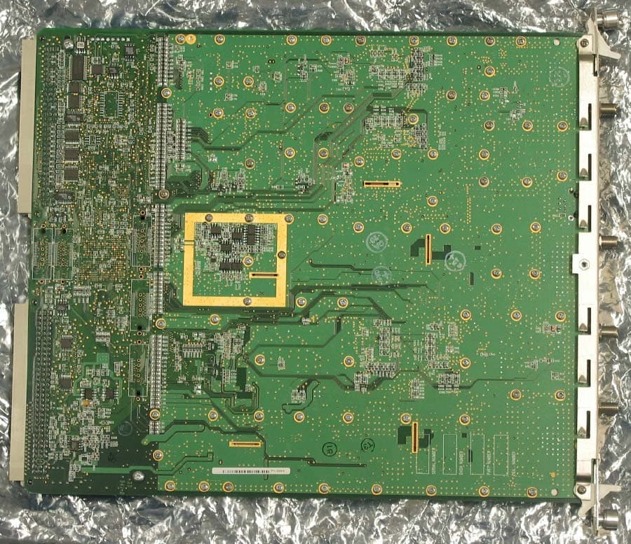
OEWAUAC85
Mar 03, 2003Ultra WAVE BTS
Equipment Class
TNB - Licensed Non-Broadcast Station Transmitter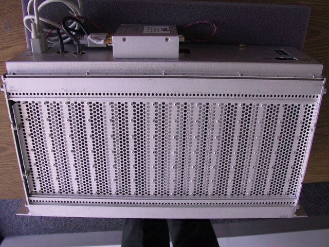
OEW-AGBB
Feb 04, 2003CDMA2000 Wireless Basestation
Equipment Class
AMP - Amplifier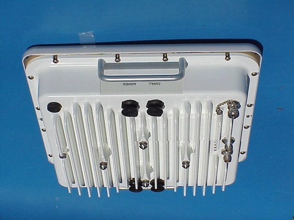
OEWCX-DS3-53G
Jul 25, 2002Point to Point DSX3 / IP Transceiver
Equipment Class
NII - Unlicensed National Information Infrastructure TX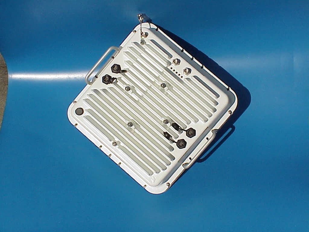
OEWCX-DS3-58G
Jul 24, 2002Point to Point DSX3 / IP Transceiver
Equipment Class
DTS - Digital Transmission System