OEWCX-DS3-53GPoint to Point DSX3 / IP Transceiver
ADC Telecommunications Inc.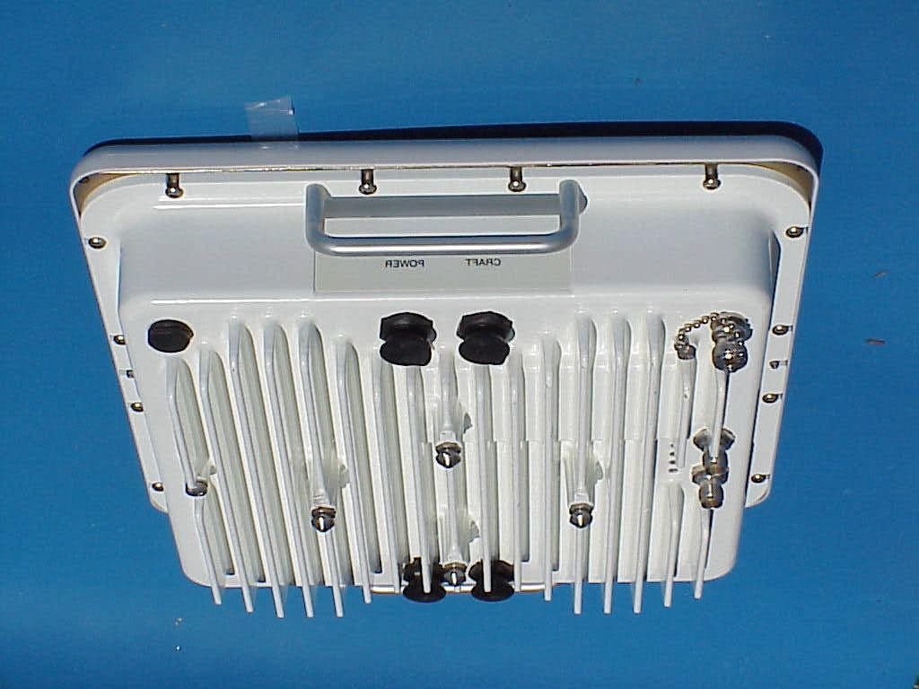
Click to zoom
Application Details
- Equipment Class
- NII - Unlicensed National Information Infrastructure TX
- Date of Grant
- Jul 25, 2002
- Application Purpose
- Original Equipment
- Date of Application
- Jul 25, 2002
- Equipment Note
- Point to Point DSX3 / IP Transceiver
- Frequency Range
- 5262.00000000 - 5338.00000000
- Company
- ADC Telecommunications Inc.
- Country
- United States
Documents & Files
Document Text
Text extracted from the exhibit documents filed with the FCC. Open a document above to read the original.
Users Manual
(FCC Certified Version) Part Number 100757-001 5/02 Version A WaveNet Link CX User Manual ii The products described in this document are products of interWAVE Communications, Inc. or its licensers. No part of this document may be photocopied, reproduced, translated, transferred, disclosed or otherwise provided to third parties without the prior written consent of an officer of interWAVE Communications, Inc. This document applies to the interWAVE Communications, Inc. release of the WaveNet Link product line and to all subsequent versions and releases of the hardware or software unless otherwise indicated in a new version or an update package for this edition. Publications requests should be addressed to your local sales support office. interWAVE Communications, Inc. reserves the right to make changes to any products described herein at any time without notice. interWAVE Communications, Inc. does not assume any responsibility or liability arising out of the application or use of any product described herein, except as expressly agreed to in writing by interWAVE Communications, Inc. nor does the purchase or use of a product from interWAVE Communica- tions, Inc. convey a license under any patent rights, copyrights, trademark rights, or any other of the intellectual property rights of interWAVE Communications, Inc. or third parties. Use, duplication, or disclosure by the U.S. Government is subject to restrictions of FAR 52.227-14 (g) (2) (6/87) and FAR 52.227-19 (6/87), or DFAR 252.227-7015 (b) (6/95) and DFAR 227.7202-3 (a). The software described in this document is furnished under a license agreement or nondisclosure agreement. The software may be used or copied only in accordance with the terms of the agreement. It is a violation of interWAVE Communications, Inc. proprietary rights to copy the software on any medium except as specifically allowed in the license or nondisclosure agreement. interWAVE and interWAVE Communica- tions, Ltd. hold the following United States Patents: No. 5,577,029, No. 5,654,968, No. 5,682,403, No. 5,721,735, No. 5,734,699, No. 5,734,979, No. 5,761,195, No. 5,781,582, No. 5,818,824, No. 5,842,138, No. 5,887,256, No. 5,953,651, No. 5,957,464, No. 5,999,813, No. 6,070,071, No. 6,078,823, No. 6,081,716, No. 6,101,400, No. 6,169,907, No. 6,173,177, No. 6,212,395, No. 6,269,255, No. USP D 391,967, No. USP D 391,968, No. USP D 397,693. Trademark Acknowledgment interWAVE, WaveNet, WaveNet Access, WaveNet Link, WaveNet Transport, Broadband Without Boundaries, StarPort, and StreamNet are trademarks or registered trademarks of interWAVE Communications, Inc. All other trademarks, service marks and product names mentioned in this document are the property of their respective owners. ©2002 interWAVE Communications, Inc. All Rights Reserved. iii United States Federal Communications Commission Required User Documentation This equipment complies with Part 15 of the FCC Rules. Operation is subject to the following two conditions: (1) this device may not cause harmful interference, and (2) this device must accept any interference received, including interference that may cause undesired operation. Changes or modifications not expressly approved by interWAVE in writing can void the user’s authority to operate this equipment. This device must be professionally installed. This device is to be exclusively used for fixed point-to-point operation with directional antennas. iv Link CX User Manual, Version A (this page intentionally left blank) v Table of Contents Welcome! . . . . . . . . . . . . . . . . . . . . . . . . . . . . . . . . . . . . . . . . . . . . . . . . . . . . . . . . . . . . . . . . . . . . . . . . ix Document Organization . . . . . . . . . . . . . . . . . . . . . . . . . . . . . . . . . . . . . . . . . . . . . . . . . . . . . . . . . . . . . ix Microwave Radiation Warnings . . . . . . . . . . . . . . . . . . . . . . . . . . . . . . . . . . . . . . . . . . . . . . . . . . . . . . . . ix Related Documentation . . . . . . . . . . . . . . . . . . . . . . . . . . . . . . . . . . . . . . . . . . . . . . . . . . . . . . . . . . . . .xii Customer Support Services . . . . . . . . . . . . . . . . . . . . . . . . . . . . . . . . . . . . . . . . . . . . . . . . . . . . . . . . . xiii Conventions Used in this Manual . . . . . . . . . . . . . . . . . . . . . . . . . . . . . . . . . . . . . . . . . . . . . . . . . . . . . xv Chapter 1 System Description . . . . . . . . . . . . . . . . . . . . . . . . . . . . . . . . . . . . . . . . . . . . . . . . . . . . . . . 1 1-1 General . . . . . . . . . . . . . . . . . . . . . . . . . . . . . . . . . . . . . . . . . . . . . . . . . . . . . . . . . . . . . . . . . . . . . . 1 1-1.1 Products . . . . . . . . . . . . . . . . . . . . . . . . . . . . . . . . . . . . . . . . . . . . . . . . . . . . . . . . . . . . 1 1-1.2 Applications . . . . . . . . . . . . . . . . . . . . . . . . . . . . . . . . . . . . . . . . . . . . . . . . . . . . . . . . . . 2 1-2 System Overview . . . . . . . . . . . . . . . . . . . . . . . . . . . . . . . . . . . . . . . . . . . . . . . . . . . . . . . . . . . . . . 2 1-3 Features . . . . . . . . . . . . . . . . . . . . . . . . . . . . . . . . . . . . . . . . . . . . . . . . . . . . . . . . . . . . . . . . . . . . . 5 1-4 Link CX Basic Structure . . . . . . . . . . . . . . . . . . . . . . . . . . . . . . . . . . . . . . . . . . . . . . . . . . . . . . . . . 6 1-4.1 Radio Links . . . . . . . . . . . . . . . . . . . . . . . . . . . . . . . . . . . . . . . . . . . . . . . . . . . . . . . . . . 6 1-4.2 Data Stream . . . . . . . . . . . . . . . . . . . . . . . . . . . . . . . . . . . . . . . . . . . . . . . . . . . . . . . . . . 6 1-4.3 Link CX Models . . . . . . . . . . . . . . . . . . . . . . . . . . . . . . . . . . . . . . . . . . . . . . . . . . . . . . . 6 1-4.4 Mounting and Antenna Alignment . . . . . . . . . . . . . . . . . . . . . . . . . . . . . . . . . . . . . . . . 7 1-4.5 Interface Connectors and Indicators . . . . . . . …
Text truncated - open the document above for the full version.
Cover Letter(s)
From: Mark Schutzer [[email protected]] Sent: Wednesday, July 24, 2002 10:53 AM To: Mike Kuo Cc: Tom Cokenias (E-mail) Subject: RE: interWAVE Communications, Inc., FCC ID:OEWCX-DS3-53G, An02T2050 Mike, I have uploaded the additional files, additionalplots.pdf, and additional_53_letter.pdf that contain the power measurements as requested. Please let me know if you have any questions concerning the measurements. Regards, Mark Schutzer Director of Technology interWAVE Communications, Inc. > -----Original Message----- > From: Mike Kuo [mailto:[email protected]] > Sent: Tuesday, July 23, 2002 9:54 AM > To: '[email protected]' > Cc: Tom Cokenias (E-mail) > Subject: FW: interWAVE Communications, Inc., FCC ID:OEWCX-DS3-53G, > An02T20 50 > > > > > -----Original Message----- > From: CERTADM > Sent: Monday, July 22, 2002 6:37 PM > To: '[email protected]' > Subject: interWAVE Communications, Inc., FCC ID:OEWCX-DS3-53G, An02T2050 > > > Notice_content > ------------- > Question #1: Peak conducted transmit output power: As stated in the main > test report, the test procedure adopted in ETSI 300 328. ETSI 300 328 is > used for Wireless LAN with frequency range from 2400 -2483.5MHz. > The EUT is > 5.8GHz UNII transceiver which is not applicable to ETSI 300 328. The ETSI > standards which are related to 5.8GHz transceiver are : Draft EN > 301 393 and > ETSI 300 836. However, the test procedure indicated in these two > documents > are for EIRP measurements. The guideline for measuring UNII Peak output > power has been discussed among industrial and FCC did make some changes. > > The newest guideline in performing the peak conducted output power are : > > Please remeasure the output power in accordance with the > following. List the > method used, and list the VBW for each data. > > Peak conducted transmit output power. > Peak output power shall be measured with no video averaging and > with a video > bandwidth (VBW) greater than or equal to the larger of: > -- EBW/(2*pi*30), where EBW is the 26-dB emission bandwidth > -- 1/(2*pi*T), where T is the transmission pulse duration over which the > transmission is continuous and average symbol envelope power is constant. > > Compliance with either of the following methods is acceptable. > 1) Use a peak power meter applicable for the transmission pulse duration. > Any low-pass filtering in the meter must comply with the VBW requirement > above. > > 2) Use an analyzer with resolution bandwidth (RBW) greater than emission > bandwidth.* Use a video filter with VBW as specified above. Use peak > detector and max hold settings with no averaging. Analyzer should be in > linear (rather than log) display mode. > * For Broadband emissions where the available analyzer bandwidth is less > than emission bandwidth, set RBW = 1 MHz and V > BW as specified above. Use peak detector and max hold settings with > no averaging. The analyzer should be in linear (rather than log) display > mode. Compute power by integrating the spectrum across the 26-dB EBW or > apply a bandwidth correction factor of 10log(EBW/1 MHz) to the > spectral peak > of the emission. The integration can be performed using the spectrum > analyzer's band power measurement function with band limits set > equal to the > EBW band edges or by summing power levels in each 1-MHz band in > linear power > terms. The 1-MHz band power levels to be summed can be obtained by > averaging, in linear power terms, the peak-detected,max-hold > power levels in > each frequency bin across the 1 MHz. > > Please note: If the measured output power is different than the value that > are documented in the test report, the main test report, MPE calculation > must be updated in accordance with newly measured value. > > Best Regards > > > Mike Kuo / TCB Certifier > The items indicated above must be submitted before processing can continue > on the above referenced application. Failure to provide the requested > information within 60 days of the original e-mail date may result in > application dismissal and forfeiture of the filing fee. Also, please note > that partial responses increase processing time and should not be > submitted. > Any questions about the content of this correspondence should be > directed to > the e-mail address listed below the name of the sender. >
Cover Letter(s)
FCC Laboratories 7435 Oakland Mills Road Columbia, MD 21040 May 23, 2002 To whom it may concern: This letter contains a request for confidentiality for certain documents relating to interWAVE Communications, Inc. application for type certification, OEWCX-DS3-53G. We interWAVE Communications, Inc. request that the following documents (attachments) be treated as confidential: FilenameDescription attachment_b.pdfCircuit and product description attachment_c.pdfLink CX block diagrams attachment_d.pdfLink CX schematic This request is being made per rule sections 0.459(a) and 0.459(b). These materials are confidential design documents that contain interWAVE’s trade secrets. Sincerely, Mark Schutzer Director of Technology interWAVE Communications, Inc.
Cover Letter(s)
interWAVE Communications, Inc.FCC ID: OEWCX-DS3-53G July 24, 2002 Compliance Certification Services 561F Monterey Rd. Morgan Hill, CA 95037-9001 RE: Additional information for FCC ID: OEWCX-DS3-53G / AN02T2050 We are supplying additional measurement data for our submission per your email request of July 22, 2002. Please see the attached data plots and the explanations below. Per your request the peak power was measured using the technique described in the latest FCC guideline. As the Link CX is a wide band radio, the peak power was measured using a spectrum analyzer, and a bandwidth correction factor of 10 log (EBW / 1 MHz) was applied. The 26 dB emission bandwidth (EBW) of the Link CX is 13.9 MHz, which translates to a correction factor of 11.43 dB. Per the guideline a 1 MHz resolution bandwidth was used, along with a 100 kHz video bandwidth. The video bandwidth follows the guideline as it is greater than the minimum requirement of: EBW / (2π*30) = 13.9 MHz / (2π*30) = 73.7 kHz. The spectrum analyzer was set in linear mode, no averaging, with the peak hold function on. An additional 0.6 dB correction factor was used to account for the cable loss between the Link CX and the input of the spectrum analyzer. Please see attached analyzer plots (labeled plot 1 through plot 4) showing the power measurements. The table below shows the power readings, conversions, and correction factors for each of the channels that the Link CX operates on. Channel121’2’ Power reading from analyzer in mV. 122.7 mV127.6 mV130.2 mV123.7 mV Power reading from analyzer in dBm. -5.21 dBm-4.87 dBm-4.70 dBm-5.14 dBm Bandwidth correction factor in dB. 11.43 dB11.43 dB11.43 dB11.43 dB Cable loss in dB.0.6 dB0.6 dB0.6 dB0.6 dB Peak Power reading in dBm +6.82 dBm+7.16 dBm+7.33 dBm+6.89 dBm interWAVE Communications, Inc.FCC ID: OEWCX-DS3-53G The Link CX is compliant with the requirement that the peak transmitter power be less than or equal to +7.4 dBm maximum. Best Regards, Mark Schutzer Director of Technology interWAVE Communications, Inc.
External Photos
Attachment G1, Link CX external photographsFCC ID: OEWCX-DS3-53G 1 Link CX external view (Integral antenna) Attachment G1, Link CX external photographsFCC ID: OEWCX-DS3-53G 2 Link CX, FCC ID label location Attachment G1, Link CX external photographsFCC ID: OEWCX-DS3-53G 3 Link CX rear view (Integral antenna) Attachment G1, Link CX external photographsFCC ID: OEWCX-DS3-53G 4 Link CX external side view showing 10 / 100 base-T connectors Attachment G1, Link CX external photographsFCC ID: OEWCX-DS3-53G 5 Link CX external side view showing DS3 connectors and LED windows Attachment G1, Link CX external photographsFCC ID: OEWCX-DS3-53G 6 Link CX external side view showing power and craft connectors
ID Label/Location Info
Attachment G3, Link CX FCC ID photographsFCC ID: OEWCX-DS3-53G 1 Link CX, FCC ID label location Attachment G3, Link CX FCC ID photographsFCC ID: OEWCX-DS3-53G 2 Link CX, FCC identification label
Internal Photos
Attachment G2, Link CX internal photographsFCC ID: OEWCX-DS3-53G Link CX integral antenna attachment Attachment G2, Link CX internal photographsFCC ID: OEWCX-DS3-53G Link CX view of PCB in enclosure with shields and duplexer Attachment G2, Link CX internal photographsFCC ID: OEWCX-DS3-53G Link CX view of PCB in enclosure without shields Attachment G2, Link CX internal photographsFCC ID: OEWCX-DS3-53G Link CX view of enclosure bottom Attachment G2, Link CX internal photographsFCC ID: OEWCX-DS3-53G Link CX integral antenna front view Attachment G2, Link CX internal photographsFCC ID: OEWCX-DS3-53G Link CX integral antenna, backside view Attachment G2, Link CX internal photographsFCC ID: OEWCX-DS3-53G Link CX pcb top view with shields in place Attachment G2, Link CX internal photographsFCC ID: OEWCX-DS3-53G Link CX pcb bottom view with shields in place Attachment G2, Link CX internal photographsFCC ID: OEWCX-DS3-53G Link CX pcb top view without shields Attachment G2, Link CX internal photographsFCC ID: OEWCX-DS3-53G Link CX pcb top view, RF section close-up Attachment G2, Link CX internal photographsFCC ID: OEWCX-DS3-53G Link CX pcb bottom view without shields Attachment G2, Link CX internal photographsFCC ID: OEWCX-DS3-53G Link CX pcb bottom view, RF section close-up Attachment G2, Link CX internal photographsFCC ID: OEWCX-DS3-53G Link CX shields, outside facing surfaces Attachment G2, Link CX internal photographsFCC ID: OEWCX-DS3-53G Link CX shields, inside facing surfaces Attachment G2, Link CX internal photographsFCC ID: OEWCX-DS3-53G Link CX duplexer, top view Attachment G2, Link CX internal photographsFCC ID: OEWCX-DS3-53G Link CX duplexer, bottom view
Parts List/Tune Up Info
Attachment HFCC ID: OEWCX-DS3-53G interWave Communications 312 Constitution Drive, Menlo Park, CA 94025 • ( (650) 838-2000 • Fax (650) 321-6281 1 of 3 SOURCE CONTROL DRAWING100499-001 ____________________________________________________________________________ Part Number:100499-001 PART:12” x 12” integral flat panel DATE:10/08/2001 DOCUMENT REVISION:Release 1 PART REVISION:1 ORIGINATOR:Lam Huynh / Stuart Taylor ECNC00442 ____________________________________________________________________________ Antenna Type:Integral panel antenna Operating Frequency:5.25 – 5.35 GHz and 5.725 – 5.825 GHz Bore-sight gain:21.0 dBi, including cable loss, (21 dBi +/- 0.5 dB) Beamwidth –3 dB11 ± 2° on both azimuth and elevation planes Beamwidth –20 dB 5.25 – 5.35 GHz:36° max on azimuth, 48° max on elevation planes 5.725 – 5.825 GHz:36° max on both azimuth and elevation planes Polarization:either vertical or horizontal by 90° plane rotation Side lobe peaks:20 dB min on both planes ( when mounted in 45° diamond position) Antenna radiation envelope:see typical antenna profile Front-to-back ratio:-30 dB min when mounted on CX radio mechanical box Cross-polarization:-30 dB min within 3dB beamwidth, -20 dB elsewhere VSWR ( with radome): 1.5:1 nom, 1.7:1 max RF interface:SMP female on 0.085” flex cable, 6” long ( Recommended CDI P/N P657-3705-1CC female straight to flex cable or equivalent. Recommended double-shielded cable but single-shielded cable is acceptable if min antenna gain is met) Labeling:Frequency and polarization must be labeled at RF nterfaces. Part must be labeled with Vendor Name or ID Attachment HFCC ID: OEWCX-DS3-53G interWave Communications 312 Constitution Drive, Menlo Park, CA 94025 • ( (650) 838-2000 • Fax (650) 321-6281 2 of 3 SOURCE CONTROL DRAWING100499-001 ____________________________________________________________________________ Iand Date Code. Radome:white, molded Antenna finish:TBD Antenna mount:integral to radio mechanics, in diamond position See tattached mechanical interface drawing Weight:TBD Size:fit in 12” x 12” radome Wind load:N/A Operating temperature:-40°C to +60°C Environmental exposure:Humidity test, dust test, salt fog test performed in accordance with FA-903000, Rev.1, which references MIL-STD-810E Vendor: TBD Vendor Part Number:TBD Appendix A: typical azimuth beam pattern FLAT PANEL ANTENNA PROFILE -35 -30 -25 -20 -15 -10 -5 0 -180-135-90-4504590135180 azimuth (0) relative gain ( dBc) Co-pol X-pol Attachment HFCC ID: OEWCX-DS3-53G interWave Communications 312 Constitution Drive, Menlo Park, CA 94025 • ( (650) 838-2000 • Fax (650) 321-6281 3 of 3 SOURCE CONTROL DRAWING100499-001 Appendix C. CDI SMP connector specification ( for reference only)
RF Exposure Info
FCC ID: OEWCX-DS3-53GinterWAVE Communications, Inc 1 15.407 (f), RF exposure requirements As of October 15, 1997, all products must address the issue of Human Exposure to RF electromagnetic fields. Referring to OET Bulletin 65, the limits for Occupational exposure, and General Population exposure are 5 mW/cm 2 and 1 mW/cm 2 , respectively, above 1.5 GHz. The Link CX radio transmits a maximum of –1.0 dBm (0.8 mW) average power into a 21 dBi integral flat panel antenna. The 21 dBi gain of the integral antenna has a decimal gain (G) of 126, i.e. 10 21/10 . The duty cycle of the transmitter is 100%. A maximum EIRP of +20 dBm would occur at the site when the radio is operating in a fixed, point to point configuration. RF power density can be calculated with the equation: S = P ∗ G / 4π R 2 , where S = power density in mW/cm, P = power input to the antenna in mW, G = power gain of the antenna, and R = distance to the center of radiation of the antenna in cm. By rearranging this equation, the relationship between distance (R) and Power Density (S) can be found. Rearranging R =√(PG / 4π S), and solving for the maximum limits of 5 mW/ cm 2 , and 1 mW/ cm 2 we have: R(5 mW/cm 2 ) = √ 0.8 mW ∗ 126 / 4π ∗ 5 = 1.3 cm, or .51-inches. R(1 mW/cm 2 ) = √ 0.8 mW ∗ 126 / 4π ∗ 1 = 2.8 cm, or 1.1-inches. These results show that the general population RF exposure limits are not exceeded as long as the general population is kept 1.1-inches from the feed point of the antenna. The propagation characteristics at 5.3 GHz dictate a line-of-sight type of RF path. As such, typical installation locations are up on rooftops or masts to get above ground level path obstructions. When the Link CX is installed in this manner, the general population will be further than 1.1-inches from the antenna, and RF exposure limits will be met. As this application is being processed by a Telecommunications Certification Body there is a requirement that the antenna be installed in such a way that the general population is kept at least 2 meters, or 78 inches away from the main beam radiation of the antenna. The Link CX is intended for professional installation only, and the product’s manual contains appropriate warnings concerning RF exposure, and instructions to place and mount the antenna to maintain a minimum of 2 meters, or 78 inches from general population contact. FCC ID: OEWCX-DS3-53GinterWAVE Communications, Inc 2 RF exposure – Installation issues The Link CX is intended to be installed and mounted with the DC power off to avoid any RF exposure potential. Appropriate instructions are supplied in the product manual. After the unit is mounted, the antenna must be aligned with the other end of the link. While a compass is used for rough alignment, final alignment of the antenna is done by monitoring the strength of the signal from the far end of the link. As the Link CX is a full duplex unit, there is a potential for exposure to RF energy during the antenna alignment process. The manual cautions the installer to always remain behind the antenna during the alignment process. If the integral antenna is used, the entire Link CX enclosure is rotated in elevation and azimuth to align the antenna. The following section will calculate the RF exposure potential to the installer during antenna alignment. The gain of the antenna has been modified by the specified front to back ratio as specified in the antenna’s source control drawing. The table below shows the characteristics of the integral antenna used on the Link CX. Antenna typeGain (dBi) Front to Back Ratio (dB) Net Backwards Gain (dBi) Integral antenna+21.030-9.0 The reverse gain of –9.0 dBi (G = .126) will be used to examine the exposure potential to the installer. Once again, using the equations from the previous section, the minimum distances that meet the RF exposure guidelines are: R(5 mW/cm 2 ) = √ 0.8mW ∗ .126 / 4π ∗ 5 = .040-cm, or .015-inches. R(1 mW/cm 2 ) = √ 0.8 mW ∗ .126 / 4π ∗ 1 = .089-cm, or .035-inches. These equations show that RF exposure guidelines are complied with as long as the installer remains at least .1-cm (rounded) behind the primary reflector of the antenna during the alignment process. The integral antenna and its reflector is mounted on one side of the Link CX enclosure. The 7-cm thickness of the Link CX enclosure prevents the installer from getting close to the reflector of the antenna. The manual cautions the installer to always align the antenna from the backside, and to avoid exposure from the front of the antenna.
Test Report
FCC ID: OEWCX-DS3-53GinterWAVE Communications, Inc 1 LINK CX (5.3 GHz UNII) Application for FCC Certification Abstract This document provides information required for the FCC type Certification application. FCC ID: OEWCX-DS3-53GinterWAVE Communications, Inc 2 Section 2.1033, Application for Certification The following information is being submitted in support of interWAVE’s application for type certification of its Link CX product operating under the part 15, subpart E – UNII rules. This document is written in a format that lists each of the appropriate rule sections, along with documentation showing compliance with each section. The information will be either directly presented in this document, or a supporting attachment will be referenced. The Link CX is a point to point radio that transmits a raw data rate of 50 Mbits/sec in approximately 14 MHz of emission bandwidth. The radio is using 16 QAM modulation with an excess bandwidth of 15% to achieve excellent spectrum efficiency. External interfaces to the radio include coaxial DS3 rate data, and two 10/100 base-T Ethernet interfaces. The table below summarizes the technical parameters of the Link CX. ParameterDescription Frequency Band5250 – 5350 MHz, UNII per 15.407 Mode of OperationFull Duplex, 100% duty cycle Channel spacing16 MHz Transmit / Receive separation60 MHz Number of channel pairs2 Channel pair #15262 MHz / 5322 MHz Channel pair #25278 MHz / 5338 MHz Modulation 16 QAM, α = 0.15 Emission Bandwidth (26 dB)13.9 MHz Frequency Stability+/- 5.0 PPM Maximum output power-1.0 dBm average (+7.4 dBm peak) Antenna typeIntegral flat panel Antenna gain21 dBi User interfacesDSX3 coaxial, 10/100 base-T Ethernet, craft RS-232 interface FCC ID: OEWCX-DS3-53GinterWAVE Communications, Inc 3 Section 2.1033 (b)(1), Name of applicant / manufacturer The applicant and manufacturer of the Link CX is: interWAVE Communications, Inc. 312 Constitution Drive Menlo Park, CA 94025-1164 Section 2.1033 (b)(2), FCC identifier The FCC identifier for the Link CX is OEWCX-DS3-53G. Section 2.1033 (b)(3), Copy of installation manual See attachment A (attachment_a.pdf) for a copy of the installation and operating manual. The installation manual covers both the 5.3 GHz product and a 5.8 GHz version of the Link CX. The 5.8 GHz version of the Link CX is being certified under a separate concurrent application. Please see the manual section that discusses the regulatory information, along with the differences in the 5.3 GHz and 5.8 GHz versions of the product. Section 2.1033 (b)(4), Circuit description See attachment B (attachment_b.pdf) for a product and circuit description of the Link CX. Section 2.1033 (b)(5), Block diagrams and schematics See attachment C (attachment_c.pdf) for the Link CX block diagrams, and attachment D (attachment_d.pdf) for a copy of the Link CX board schematic. Section 2.1033 (b)(6), Technical compliance data See the following sections illustrating part 15 requirements and measurements. Unless otherwise stated all measurements were performed in interWAVE’s engineering laboratory on May 14 th of the year 2002. See appendix C for a serialized list of test equipment and radios used for the testing. Section 15.203, Antenna requirements The Link CX uses an integral antenna that also forms the top of the enclosure. The antenna is permanently attached to the enclosure, and therefore is compliant with the requirements of this section. In addition the Link CX is intended for professional installation only. The following section that describes the market that the Link CX is going to be sold into. FCC ID: OEWCX-DS3-53GinterWAVE Communications, Inc 4 Justification for professional installation Marketing and Application The Link CX system has been designed and is intended for use as an alternative to traditional wireline methods of providing DS3 and High-Speed Ethernet connectivity. As such the end user of this system will be enterprise businesses, local telephone companies or utility companies. The actual customer for, and operator of Link CX networks will be Service Providers such as ISP’s, Competitive Access Providers (CAP’s) or the local telco’s themselves. This places the use of the system decidedly in the industrial/commercial application arena. Furthermore, many of the aforementioned target customers are already involved in wireless communications technologies and have on staff professional RF installation crews. For those Service Providers who do not to date have in-house talent for the RF installation of the Link CX system, e.g. ISP’s, they will be directed to a network of third party providers (largely from the cellular/PCS arena) who specialize in microwave equipment installations. Examples of some of these support shops are Valcom in the mid-west, and Netcom International based in Atlanta. Technical Requirements There are several steps involved in the setup and installation of the system that require tools and skills not found in the average technically inclined person’s skill set. Some of these are: • Physical Installation - these units are designed and intended for outdoor installation. The units will be located on towers on tall buildings typical for microwave equipment sites. Access to these locations is typically restricted to those with authorization, which restricts access from the average lay person. Furthermore, when installing the systems weather sealing of connectors is required, an additional somewhat specialized task. • Antenna Alignment – in order to align the antennas of the system, it is necessary for the installer to adjust the antenna based upon an RSSI (Received Signal Strength Indicator) voltage measured at a test point on the radio unit • Power Requirements – The Link CX radio requires a DC voltage from 21 to 60 VDC to operate. As this is outside the normal household appliance voltage, the user must seek AC to DC or Battery systems which unique to systems requiring professional expertise or installation. FCC ID: OEWCX-DS3-53…
Text truncated - open the document above for the full version.
Test Report
Attachment E1FCC ID: OEWCX-DS3-53G 02U1259-1 020426A 04/26/029:11 AM JCH Interwave Communications Pt to Pt Radio Link, Link Cx, 5.3 GHz TX Low S/N 00644C EUT Only FCC 15.205/15.209 Transmitt 04/26/02 Freq.ReadingAFClossPre-ampLevelLimitMarginPolAzHeightMark (MHz)(dBuV)(dB)(dB)(dB)(dBuV/m)FCC_B(dB)(H/V)(Deg)(Meter)(P/Q/A) 80.3148.707.462.3931.5826.9740.00-13.033mH180.001.00P 150.0051.3016.463.4631.1140.1143.50-3.393mH180.001.00P 160.0045.8016.983.6331.0735.3443.50-8.163mH180.001.00P 199.9249.8016.564.1830.7839.7643.50-3.743mH180.001.00P 239.9957.3011.444.7230.4643.0146.00-2.993mH180.001.00P 279.9844.3013.565.2330.2932.8046.00-13.203mH180.001.00P 299.9843.6014.715.4830.2333.5646.00-12.443mH180.001.00P 350.0043.3015.166.0530.4034.1146.00-11.893mH180.001.00P 359.9952.4015.266.1730.4443.3946.00-2.613mH180.001.00P 400.0047.4015.626.6330.5839.0746.00-6.933mH180.001.00P 480.0038.4017.507.5730.8132.6546.00-13.353mH180.001.00P 650.0036.4020.229.3130.5935.3446.00-10.663mH180.001.00P Total data #: 12 V.2a Company: EUT Description: Test Configuration : Type of Test: Mode of Operation:…
Text truncated - open the document above for the full version.
Contact Information
Applicant
Mark Miska(Director of Technology)
Test Firm
Compliance Certification Services IncSteve Cheng
Technical Specifications
| # | Rule Parts | Frequency Range | Power Output |
|---|---|---|---|
| 1 | 15E | 5.26 GHz - 5.34 GHz | 5.50 mW |
Other Applications from ADC Telecommunications Inc.
OEWAKAD19
Oct 30, 2006GSM Base Station
Equipment Class
PCB - PCS Licensed Transmitter
OEW-AGBB-M1
Dec 30, 2004CDMA Cellular BaseStation
Equipment Class
PCB - PCS Licensed Transmitter
OEWAUAC85
Mar 03, 2003Ultra WAVE BTS
Equipment Class
TNB - Licensed Non-Broadcast Station Transmitter
OEW-AGBB
Feb 04, 2003CDMA2000 Wireless Basestation
Equipment Class
AMP - Amplifier
OEWCX-DS3-58G
Jul 24, 2002Point to Point DSX3 / IP Transceiver
Equipment Class
DTS - Digital Transmission System