OGUVER1650RF ID Badge Transmitter
Midmark RTLS Solutions, Inc.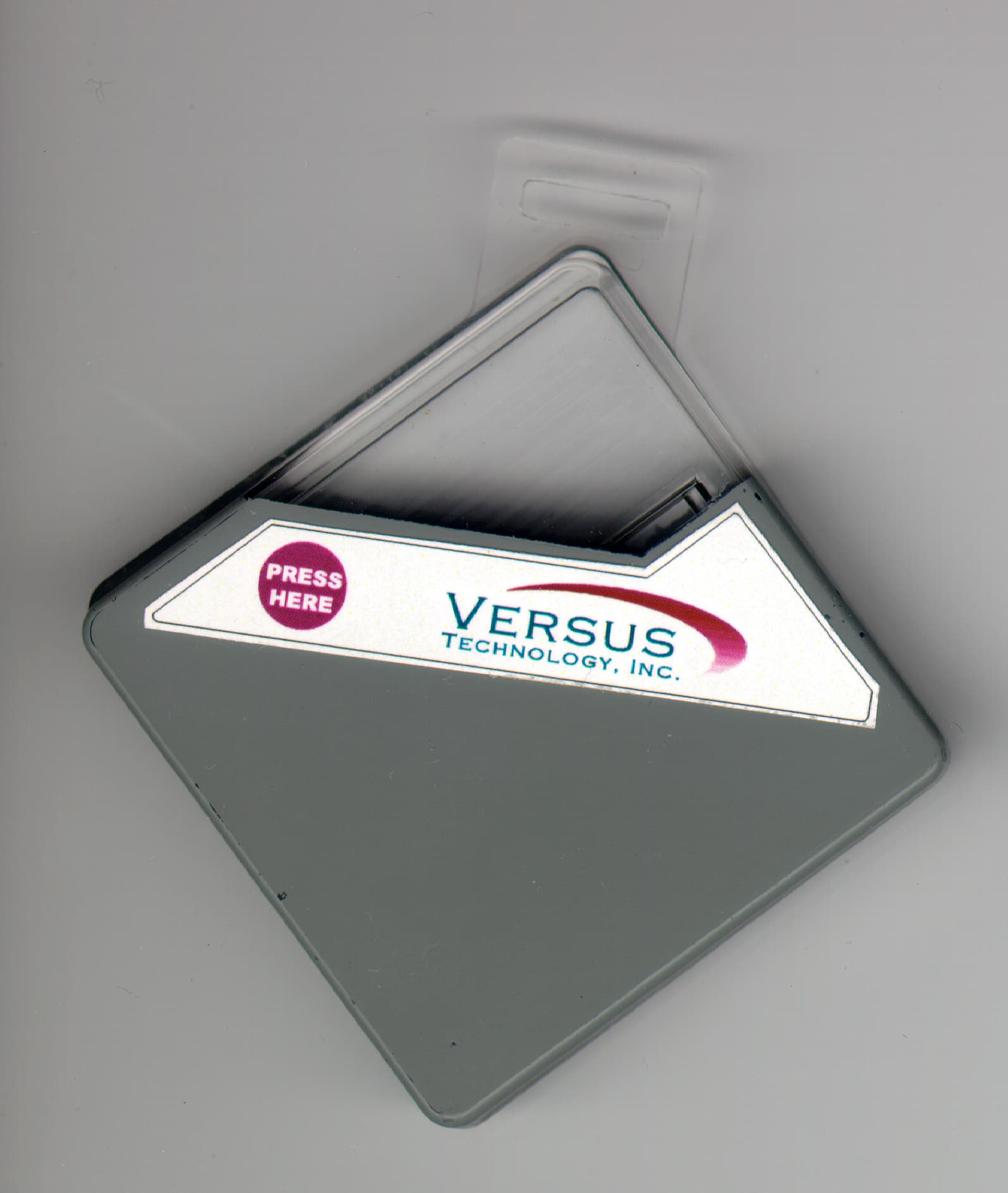
Click to zoom
Application Details
- Equipment Class
- DSC - Part 15 Security/Remote Control Transmitter
- Date of Grant
- May 19, 1999
- Application Purpose
- Original Equipment
- Date of Application
- Mar 10, 1999
- Equipment Note
- RF ID Badge Transmitter
- Frequency Range
- 433.90000000 - 433.90000000
- Company
- Midmark RTLS Solutions, Inc.
- Country
- United States
Documents & Files
Document Text
Text extracted from the exhibit documents filed with the FCC. Open a document above to read the original.
Users Manual
Hardware/Wiring Installation Guide VERSUS TECHNOLOGY, INC. 2600 M ILLER CREEK ROAD TRAVERSE CITY, MI 49684 (616) 946-5868 Versus Technology, Inc. DT10000-A0001iiRevision 8 December 1998 Copyright 1991, 1992, 1993, 1996, and 1998 Versus Technology, Inc., all rights reserved This document contains user’s information on technology that is proprietary to Versus Technology, Inc. Permitted transmittal, receipt, or possession of this document does not express license or imply any rights to use, sell, design, or manufacture this information. No reproduction, publication or disclosure of this information, in whole or in part, shall be made without prior written authorization from an officer of Versus Technology, Inc. To Clean Badges: wipe gently with damp cloth. WARNING! This product is not designed, intended, authorized or warranted for use in any life support or other application where product failure could cause or contribute to personal injury, death, or severe property damage. This component or its systems are covered by one or more of the following U.S. Patents: 5,276,496, 5,355,222; 5,119,104; 5,548,637; 5,572,195; 5,387,993; 5,027,314, 5,017,794, 4,906,853. FCC STATEMENT: Components VER-1650 and VER-4450 comply with part 15 of the FCC Rules. Operation is subject to the following two conditions: 1) This device may not cause harmful interference, and 2) this device must accept any interference received, including interference that may cause undesired operation.
Users Manual
Versus Technology, Inc. DT10000-A0001iRevision 8 December 1998 Hardware/Wiring Installation Guide VERSUS TECHNOLOGY, INC. 2600 M ILLER CREEK ROAD TRAVERSE CITY, MI 49684 (616) 946-5868 Versus Technology, Inc. DT10000-A0001iiRevision 8 December 1998 Copyright 1991, 1992, 1993, 1996, and 1998 Versus Technology, Inc., all rights reserved This document contains user’s information on technology that is proprietary to Versus Technology, Inc. Permitted transmittal, receipt, or possession of this document does not express license or imply any rights to use, sell, design, or manufacture this information. No reproduction, publication or disclosure of this information, in whole or in part, shall be made without prior written authorization from an officer of Versus Technology, Inc. To Clean Badges: wipe gently with damp cloth. WARNING! This product is not designed, intended, authorized or warranted for use in any life support or other application where product failure could cause or contribute to personal injury, death, or severe property damage. This component or its systems are covered by one or more of the following U.S. Patents: 5,276,496, 5,355,222; 5,119,104; 5,548,637; 5,572,195; 5,387,993; 5,027,314, 5,017,794, 4,906,853. FCC STATEMENT: Components VER-1650 and VER-4450 comply with part 15 of the FCC Rules. Operation is subject to the following two conditions: 1) This device may not cause harmful interference, and 2) this device must accept any interference received, including interference that may cause undesired operation. Versus Technology, Inc. DT10000-A0001iiiRevision 8 December 1998 Table of Revisions RevDateDescriptionInitialsAuthorized By: 1 3/7/96Initial Release.RAV 2 5/1/96Added Eagle speaker connections; Modified tbl. 1-1, fig. 2-1 and 2-2. RAV - -Multiple comments from reviews. Modified tbl. 3-1, 4-1, and 4-2; Added figs. 4-3, 4-5, tbl.4-3, para. 3.10, 3.11, 4.1.5 RAV 3 8/1/96Changed system name.RAV 4 Complete update to cover new high frequency equipmentDAD 5 4/2/98Complete Update/Revision of Hardware Manual to current specifications and displays. EPD 6 6/17/98Updated/Changed hardware specifications to current procedures. Added Tech Support section. Added Wire Run Check-off Diagram to manual. Changed Manual Cover Page to reflect products. EPD 7 Nov. 1998Changed collector network length diagram to represent a six collector to one concentrator specification (figure 3-2). Added to hardware section 1.4 for a display of important system components. Added to table 12-1 to include current part numbers to parts added. EPD 8 Dec. 1998Added Troubleshooting Flow Charts to section 13, for possible solutions for system hardware problems. Added Figure 7-2. Sensor Wiring Floor plan. Added Battery Replacement table Section 2.4 EPD 9 3/11/99Added FCC compliance statements for IR/RF Badge and RF SensorSKB Versus Technology, Inc. DT10000-A0001ivRevision 8 December 1998 Table of Contents SECTION PAGE # 1. INTRODUCTION........................................................................................................................................................1 1.1 P URPOSE OF THIS GUIDE...........................................................................................................................................1 1.2 S COPE OF USE...........................................................................................................................................................1 1.3 I NSTALLATION SEQUENCE........................................................................................................................................1 1.4 H ARDWARE SPECIFICATIONS / SYSTEM COMPONENTS.............................................................................................2 1.5 C OMPUTER SYSTEM REQUIREMENTS........................................................................................................................2 1.6 T ERMS AND DEFINITIONS..........................................................................................................................................2 2. SYSTEM HARDWARE DESCRIPTION..................................................................................................................5 2.1 G ENERAL..................................................................................................................................................................5 2.2 I NFRARED (IR) TRACKING........................................................................................................................................5 2.3 B ADGES....................................................................................................................................................................6 2.4 B ATTERY REPLACEMENT..........................................................................................................................................6 3. PLANNING AND INSTALLATION GUIDELINES ...............................................................................................7 3.1 G ENERAL..................................................................................................................................................................7 3.2 COLLECTOR NETWORK LENGTH LIMITATIONS..........................................................................................................8 3.3 S ENSOR CONNECTION LENGTH LIMITATIONS...........................................................................................................8 3.4 L OCATION OF COLLECTORS, AND CONCENTRATORS................................................................................................8 3.5 S ENSOR LOCATION PLANNING..................................................................................................................................9 3.6 U NDERSTANDING HIGH FREQUENCY SENSOR "FIELD-OF-VIEW"..............................................................................9 3.7 E FFECTIVE COVERAGE OF ROOMS.......…
Text truncated - open the document above for the full version.
Cover Letter(s)
1 Mr. Rich Fabina This is in reply to questions sent by the following email dated 4/30/1999, which read the following. To:Robert Wiser, Versus Technology Inc. From:Rich Fabina [email protected] FCC Application Processing Branch Re:FCC ID OGUVER1650 Applicant: Versus Technology, Inc. Correspondence Reference Number:7522 731 Confirmation Number:EA93483 Date of Original E-Mail:04/30/1999 2. Provide a letter which describes what specific exhibits in this application require confidential treatment because they are trade secrets. Remember trade secret information is only information not generally released to the public. Photographs, user's manuals and such are not trade secret information. Schematic diagrams are. The trade secret in concern deals with the way the voltage detection circuit is powered up and read by the processor. This type of configuration allows us to save the badge battery power and gives us a longer duration between battery changes. Regards, Robert Wiser Versus Technology Manufacturing Manager 1 2600 Miller Creek Road Traverse City, MI 49684 Phone: (616-946-5868) Fax: (616-946-6775)
ID Label/Location Info
Do not immerse or autoclave. This component or its systems are covered by one or more of the following U.S. Patents: 5,276,496; 5,355,222; 5,119,104; 5,548,637; 5,572,195; 5,387,993; 5,027,314; 5,017,794; 4,906,853. The FCC ID: OGUVER1650 Tested To Comply With FCC Standards Versus Technology, Inc. Writable surface area; pad printed Cleaning caution statement; pad printed Versus patent statement; pad printed Bar code; separate label Writable surface area; pad printed FCC compliance statement; pad printed
Operational Description
HARDWARE SPECIFICATIONS DESCRIPTION FEATURES Component Specifications Manufactured by Versus Technology, Inc. 2600 Miller Creek Rd., Traverse City, MI 49684 (616) 946-5868 This product or its systems are covered by one or more of the following U.S. patents: 4,906,853; 5,017,794; 5,027,314; 5,119,104; 5,276,496; 5,355,222; 5,387,993; 5,548,637; 5,572,195. The RF sensor is a superheterodyne type receiver designed to operate at 433.92 MHz receive frequency. Power is ob- tained from a collector providing 20 volts. A single wire pair is used for both power and signal. RF sensors convert encoded RF signals emitted by badges into electrical sig- nals which are transmitted to a collector via a single twisted pair connection. Each RF sensor also receives its operat- ing power across this same pair. Modulated current loop transmission signaling technology is used by each sensor for high reliability. RF sensors can be run 1000’ from col- lectors using standard unshielded twisted pair telephone type wire. RF sensors are typically mounted in a standard electrical junction box or in acoustic tile using a standard hole saw. • Durable polycarbonate construction • Standard electrical junction-box mounting plate • Ceiling mount • Spring-mounting for easy installation Size: Weight: Housing: Idle Voltage: Power: Wiring: Receive Center Frequency: Local Oscillator Frequency: Receiver Sensitivity: Receiver Input 3dB Bandwidth: Receiver Input Data Rate: Operating Temp: Installation Method: Distance: 2 3/4” x 1” 2.45 oz. Polycarbonate 16.0 vdc 295 mw 24 AWG twisted-pair 433.92 MHz 433.42 MHz (SAW-stabilized) -100dBm typ, -97dBm min 800kHz 600 bits/sec. max 0 - 125 degrees F. Use 2 3/8” hole saw Accum. run length <= 1000’ RF SENSOR Part number: VER-4450 FCC STATEMENT: Components VER-1650 and VER-4450 comply with part 15 of the FCC Rules. Operation is subject to the following two conditions: 1) This device may not cause harmful interference, and 2) this device must accept any interference received, including interference that may cause undesired operation. Modifying or tampering with the transceiver’s or receiver’s internal components can cause a malfunction, invalidate the warranty, and will void your FCC authorization to use these products.
Operational Description
HARDWARE SPECIFICATIONS DESCRIPTION FEATURES Component Specifications Manufactured by Versus Technology, Inc. 2600 Miller Creek Road, Traverse City, MI 49684 (616) 946-5868 This product or its systems are covered by one or more of the following U.S. patents: 4,906,853; 5,017,794; 5,027,314; 5,119,104; 5,276,496; 5,355,222; 5,387,993; 5,548,637; 5,572,195. This small, lightweight badge automatically transmits invisible, digitized, infrared (IR) light and radio frequency (RF) interlace containing badge identification, page requests or alert notifica- tion, and battery condition. Transmissions increase in frequency when in motion and are gradually reduced in frequency when the badge is at rest to preserve the battery life. The badge is worn on the outside of clothing easily clipped to a collar or suspended by a lanyard around the neck. A clip is pro- vided on the front face of the badge to allow for facility ID cards to be easily attached. A raised, accessible badge call button can be used to request pages or to send alerts. The IR transmissions are location-specific, as IR signal transmissions will not penetrate walls or floors. RF signals provide a supervisory signal as well as instantaneous transmission of the page request/alert button press. • Integrated with IR & RF capabilities • Communication /non-line of sight • Small and lightweight • Low battery indicator • Preset identification codes • Easy battery replacement • Page request/alert button • Durable polycarbonate construction • Passive location operation • ID badge clip Size: Weight: Housing: Battery: Angle: IR Output Type: RF Frequency: IR Wavelength: IR Range: RF Range: IR Peak Output: RF Peak Output: Duty Cycle: ID: Environmental: Storage Temp: 2" x 2" x 3/8" 1.5 oz without clothing clip Gray polycarbonate with colored polycarbonate window Standard 3 AAAA 24 degrees Digitized infrared (IR) light, non-visible 433.9 / 418 MHz 875 nanometers, 447.5 KHz 16+ feet 230+ feet 0.3 Watts ± 5% < 1 mW < 1% 16 bit ID packet, 42 bits total 32 - 125 Degrees F., 1 to 100% humidity, non-condensing 0 - 130 Degrees F., 1 to 100% humidity. COM BADGE Part number: VER-1650 Prototype. Nightingale ™
Contact Information
Applicant
Robert Wiser(Design Engineer)
Technical Contact
Versus Technology Inc.Robert L Wiser
[email protected]616-946-5868
2600 Miller Creek · Traverse City, Michigan · United States
Non-Technical Contact
Versus Technology Inc.Henry J Tenarvitz
[email protected]616-946-5868
Test Firm
Elite Electronic Engineering Co.Daniel Crowder
Technical Specifications
| # | Rule Parts | Frequency Range | Power Output | Emission | Tolerance |
|---|---|---|---|---|---|
| 1 | 15C | 433.9 MHz - 433.9 MHz | - | --- | % |
Other Applications from Midmark RTLS Solutions, Inc.
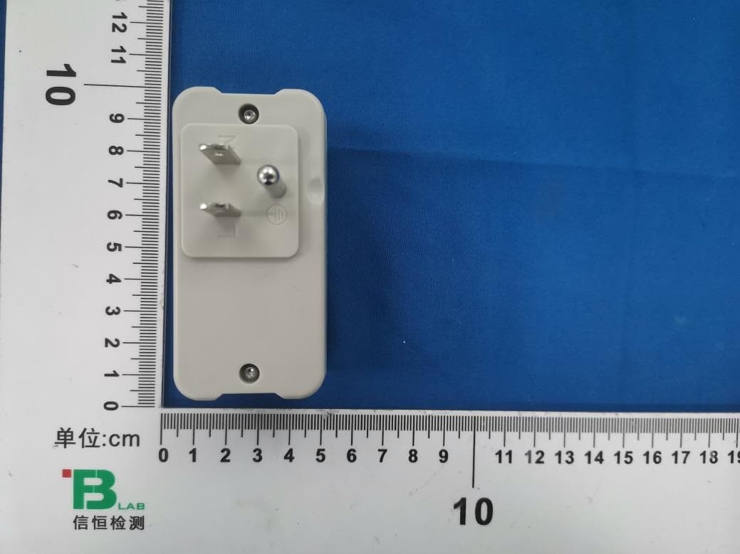
OGUVER5810
Jul 21, 2024BLE Dual band plug-in sensor
Equipment Class
NII - Unlicensed National Information Infrastructure TX
OGU722022
Oct 05, 2022Clearview BLE/IR Badge
Equipment Class
DTS - Digital Transmission System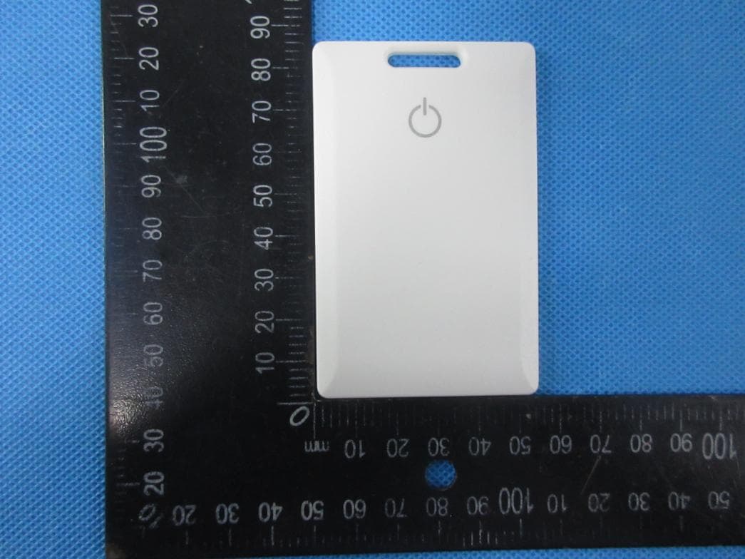
OGU702022
May 06, 2022BLE Badge
Equipment Class
DTS - Digital Transmission System
OGUVER3522
Apr 05, 2015Event Tag
Equipment Class
DSC - Part 15 Security/Remote Control Transmitter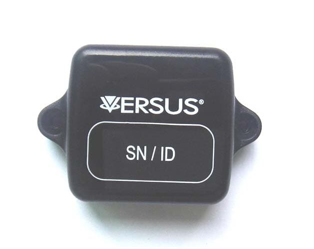
OGUVER188X
Sep 02, 2014MiniAssetTag
Equipment Class
DSC - Part 15 Security/Remote Control Transmitter