OGUVER1780IR/RF Personnal Alert Badge
Midmark RTLS Solutions, Inc.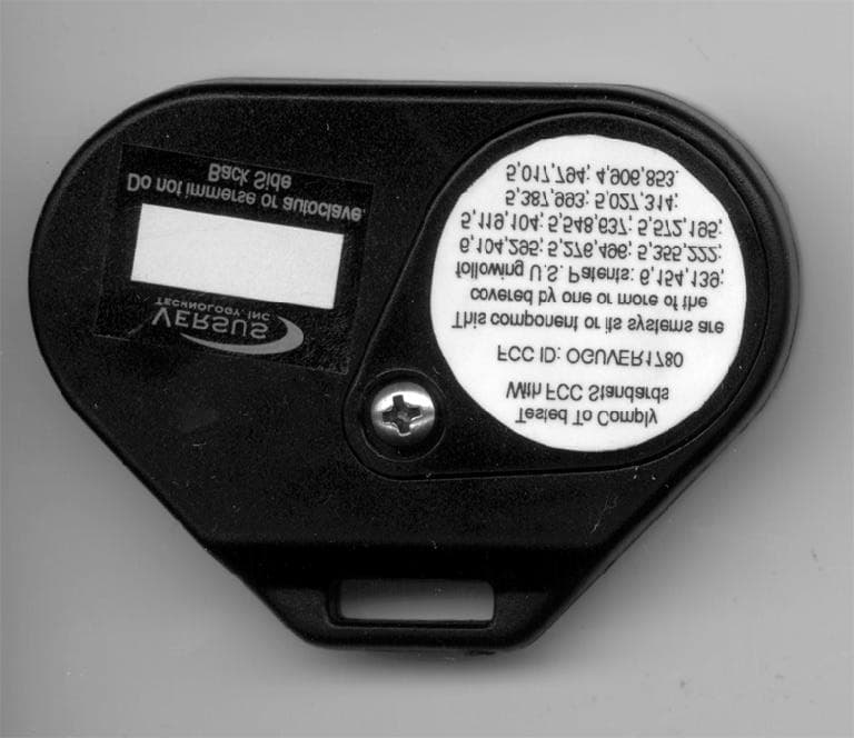
Click to zoom
Application Details
- Equipment Class
- DSC - Part 15 Security/Remote Control Transmitter
- Date of Grant
- Jun 21, 2001
- Application Purpose
- Original Equipment
- Date of Application
- Jun 21, 2001
- Equipment Note
- IR/RF Personnal Alert Badge
- Frequency Range
- 433.90000000 - 433.90000000
- Company
- Midmark RTLS Solutions, Inc.
- Country
- United States
Documents & Files
Document Text
Text extracted from the exhibit documents filed with the FCC. Open a document above to read the original.
Users Manual
Versus Information Systems Hardware and Wiring Installation Guide V ERSUS T ECHNOLOGY , I NC . 2600 M ILLER C REEK R OAD T RAVERSE C IT Y , MI 49684 (231) 946-5868 www.versustech.com i Copyright 1991, 1992, 1993, 1996, 1998, and 2000 Versus Technology, Inc., all rights reserved. This document contains user’s information on technology that is proprietary to Versus Technology, Inc. Permitted transmittal, receipt, or possession of this document does not express license or imply any rights to use, sell, design, or manufacture this information. No reproduction, publication or disclosure of this information, in whole or in part, shall be made without prior written authorization from an officer of Versus Technolo gy, Inc. WARNING! This product is not designed, intended, authorized or warranted for use in any life support or other application where product failure could cause or contribute to personal injury, death, or severe property damage. This product or its systems are covered by one or more of the following U.S. Patents: 4,906,853; 5,017,794; 5,027,314; 5,119,104; 5,276,496; 5,355,222; 5,387,993; 5,548,637; 5,572,195, 6,104,295. FCC STATEMENT: Components complying with part 15 of the FCC Rules. Operation is subject to the following two conditions: 1) This device may not cause harmful interference, and 2) this device must accept any interference received, including interference that may cause undesired operation. Modifying or tampering with the transceiver’s or receiver’s internal components can cause a malfunction, invalidate the warranty, and will void your FCC authorization to use these products. Revision date: 5/4/01 iii Contents 1.INTRODUCTION......................................................................................................................................1 1.1Purpose of This Guide......................................................................................................................1 1.2Computer System Requirements......................................................................................................1 1.3Terms and Definitions.......................................................................................................................1 1.4Parts List...........................................................................................................................................2 2.SYSTEM DESCRIPTION.........................................................................................................................3 2.1Infrared (IR) Tracking........................................................................................................................3 2.2Radio Frequency (RF) Signals..........................................................................................................3 2.3System Hardware Components........................................................................................................4 3.PLANNING THE INSTALLATION............................................................................................................7 3.1Collector and Concentrator Location Planning.................................................................................8 3.2Sensor Location Planning.................................................................................................................8 3.3Use of Unauthorized Components..................................................................................................12 3.4List of Materials...............................................................................................................................12 3.5List of Tools....................................................................................................................................12 3.6Safety and Code Considerations....................................................................................................13 4.SYSTEM HARDWARE INSTALLATION...............................................................................................15 4.1Cable Installation.............................................................................................................................15 4.2Sensor Installation...........................................................................................................................15 4.3Punch-down Block and Collector Installation..................................................................................16 4.4Connecting Sensors to Collectors...................................................................................................17 4.5Communication Room Check.........................................................................................................19 4.6Testing RF Sensors........................................................................................................................24 4.7Perimeter Activation Sentinel (PAS) Unit Installation......................................................................25 5.TROUBLESHOOTING GUIDE...............................................................................................................25 5.1Badge Battery Replacement...........................................................................................................26 6.INSTALLATION FORMS........................................................................................................................30 Hardware and Wiring Installation Guide 1 1. Introduction 1.1 Purpose of This Guide This document is intended to provide the information required to install the hardware and wiring components of a VIS system. Read this entire document before proceeding with the installation. A general understanding of wiring and telephone installation techniques is assumed. 1.2 Computer System Requirements The software runs in the Microsoft Windows 95, 98 or Windows NT environment and requires a computer system with reasonable capacity and speed. The minimum com…
Text truncated - open the document above for the full version.
Cover Letter(s)
1 Versus Technology, Inc. would like product description, block diagram and the schematic held confidential. Regards, Robert Wiser Vers us Tec hnology Engi neer 1 2600 Miller Creek Road Traverse City, MI 49684 Phone: (616-946-5868) Fax: (616-946-6775)
Test Report
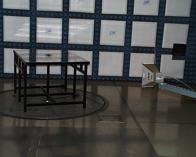
Engineering Test Report No. 05102001-A Page 1 of 21 _______________________________________________ ENGINEERING REPORT NO. 05102001-A REGARDING THE RF INTERFERENCE FROM A MODEL VER-1780 REV.1 PERSONNEL BADGE TRANSMITTER Report By: Robert Wiser Test Date: May 10, 2001 Engineering Test Report No. 05102001-A Page 2 of 21 DESCRIPTION OF TEST ITEM: Personnel Badge Transmitter MODEL NO: VER-1780 MANUFACTURER: Versus Technology, Inc. APPLICABLE SPECIFICATIONS: FCC “Code of Federal Regulations” Title 47, Part 15, Subpart C QUANTITY OF ITEMS TESTE D: One (1) TEST PERFORMED BY: ELITE ELECTRONIC ENGINEERING COMPANY Radio Interference Consultants Downers Grove, Illinois 60515 DATE RECEIVED: May 10, 2001 DATE TESTED: May 10, 2001 PERSONNEL (OPERATIONS, OBSERVERS, AND COORDINATORS): CUSTOMER: Robert Wiser of Versus Technology, Inc. was present. ELITE ELECTRONIC: Dan Crowder was test engineer ABSTRACT: The model VER-1780 Personnel Badge does meet the radiated emission requirements of the FCC “Code of Federal Regulations” Title 47, Part 15 Subpart C, Sections 15.205 et seq. For Intentional Radiators, when tested per ANSI C63.4-1992. The radiated emission level closest to the limit (worst case) occurred at 867.90 MHz. The emission level at this frequency was 2dB within the limit. See page 20 for more details. THIS REPORT SHALL NOT BE REPRODUCED, EXCEPT IN FULL, WITHOUT THE WRITTEN APPROVAL OF VERSUS TECHNOLOGY, INC. Engineering Test Report No. 05102001-A Page 3 of 21 Table of Contents Paragrap h Description of Conte nts 1.0 Introduction 1.1 Description of Test Item 1.2 Purpose 1.3 Deviations, Additions and Exclusions 1.4 Applicable Documents 1.5 Subcontractor Identification 1.6 Laboratory Conditions 2.0 Test Item Setup and Operation 2.1 Power Input 2.2 Grounding 2.3 Peripheral Equipment 2.4 Interconnect Cables 2.5 Operational Mode 3.0 Test Equipment 3.1 Test Equipment List 3.2 Calibration Traceability 3.3 Measurement Uncertainty 4.0 Requirements, Procedures and Results 4.1 Powerline Conducted Emissions 4.1.1 Requirements 4.2 Duty Cycle Factor Measurements 4.2.2 Procedures 4.2.3 Results 4.3 Radiated Measurements 4.3.1 Requirements 4.3.2 Procedures 4.3.3 Results 4.4 Occupied Bandwidth Measurements 4.4.1 Requirements 4.4.2 Procedures 4.4.3 Results 5.0 Conclusion 6.0 Certification 7.0 Endorsement Disclaimer Table I – Equipment List Total Number of pages in this document, (including data sheets): Twenty-one (21) THIS REPORT SHALL NOT BE REPRODUCED, EXCEPT IN FULL, WITHOUT THE WRITTEN APPROVAL OF VERSUS TECHNOLOGY, INC. Engineering Test Report No. 05102001-A Page 4 of 21 Measurement of RF Interference from A Model VER-1780 Personnel Badge Transmitter 1.0 Introduction: 1.1 Description of Test Item: On May 10, 2001, a series of radio interference measurements were performed on a model VER-1780 Personnel Badge Transmitter, (hereinafter referred to as the test item) serial number (not assigned). The test item was designed to transmit at approximately 433.9 MHz using an internal metallic antenna. The tests were performed for Versus Technology, Inc. of Traverse City, Michigan. 1.2 Purpose: The test series was performed to determine if the test item meets the radiated RF emission requirements of the FCC “Code of Federal Regulations” Title 47, Part 15, Subpart C, Sections for Intentional Radiators. Testing was performed in accordance with ANSI C63.4-1992. 1.3 Deviations, Additions and Exclusions: There were no deviations, additions to, or exclusions from the test specification during this test series. 1.4 Applicable Documents: The following documents of the exact issue designated form part of this document to the extent specified herein: - Federal Communications Commission “Code of Federal Regulations”, Title 47, Part 15, Subpart C, dated 1 October 1999 - ANSI C63.4-1992, “American National Standard for Methods of Measurement of Radio- Noise Emissions from Low-Voltage Electrical and Electronic Equipment in the Range of 9 kHz to 40 GHz” 1.5 Subcontractor Identification: This series of tests was performed by the Elite Electronic Engineering Company, of Downers Grove, Illinois. The laboratory is accredited by the National Institute of Standards and Technology (NIST) under the National Voluntary Laboratory Accreditation Program (NVLAP). NVLAP Lab Code: 100278-0. THIS REPORT SHALL NOT BE REPRODUCED, EXCEPT IN FULL, WITHOUT THE WRITTEN APPROVAL OF VERSUS TECHNOLOGY, INC. Engineering Test Report No. 05102001-A Page 5 of 21 1.6 Laboratory Conditions: The temperature at the time of the test was 20°C and the relative humidity was 25%. 2.0 Test Item Setup and Operation: 2.1 Power Input: The test item received 3.0 VDC from internal battery. 2.2 Grounding: Since the test item was powered with 3.0 VDC through a battery, it was ungrounded during the tests. 2.3 Peripheral Equipment: There wasn’t any peripheral equipment. 2.4 Interconnect Cables: There were no interconnect cables. 2.5 Operational Mode: For all tests the test item was energized and placed on a 80cm high non- conductive stand. For all tests, the test item was set to CW mode, thereby setting the unit to transmit continuously. The battery voltage was periodically checked to ensure proper operation at maximum level. The tests were performed with the test item operating at 433.9MHz. 3.0 Test Equipment: 3.1 Test Equipment List: A list of the test equipment used can be found on Table I page 15. All equipment was calibrated per the instruction manuals supplied by the manufacturer. The fundamental, harmonics and spurious emissions were measured with an HP 8566B spectrum analyzer. The spectrum analyzer peak-detected readings were converted to average readings using a duty cycle factor. All measurements were taken with the resolution and video bandwidth of the measuring instrument adjusted to 100k Hz below 1GHz and 1MHz above 1GHz. The duty cycle factor was calculated from the pulse train for the test item. A data plot was obtained to determine the duty cycle factor. The duty cyc…
Text truncated - open the document above for the full version.
Contact Information
Applicant
Robert Wiser(Design Engineer)
Test Firm
Elite Electronic Engineering Co.Daniel Crowder
Technical Specifications
| # | Rule Parts | Frequency Range | Power Output |
|---|---|---|---|
| 1 | 15.231(e) | 433.9 MHz - 433.9 MHz | - |
Other Applications from Midmark RTLS Solutions, Inc.
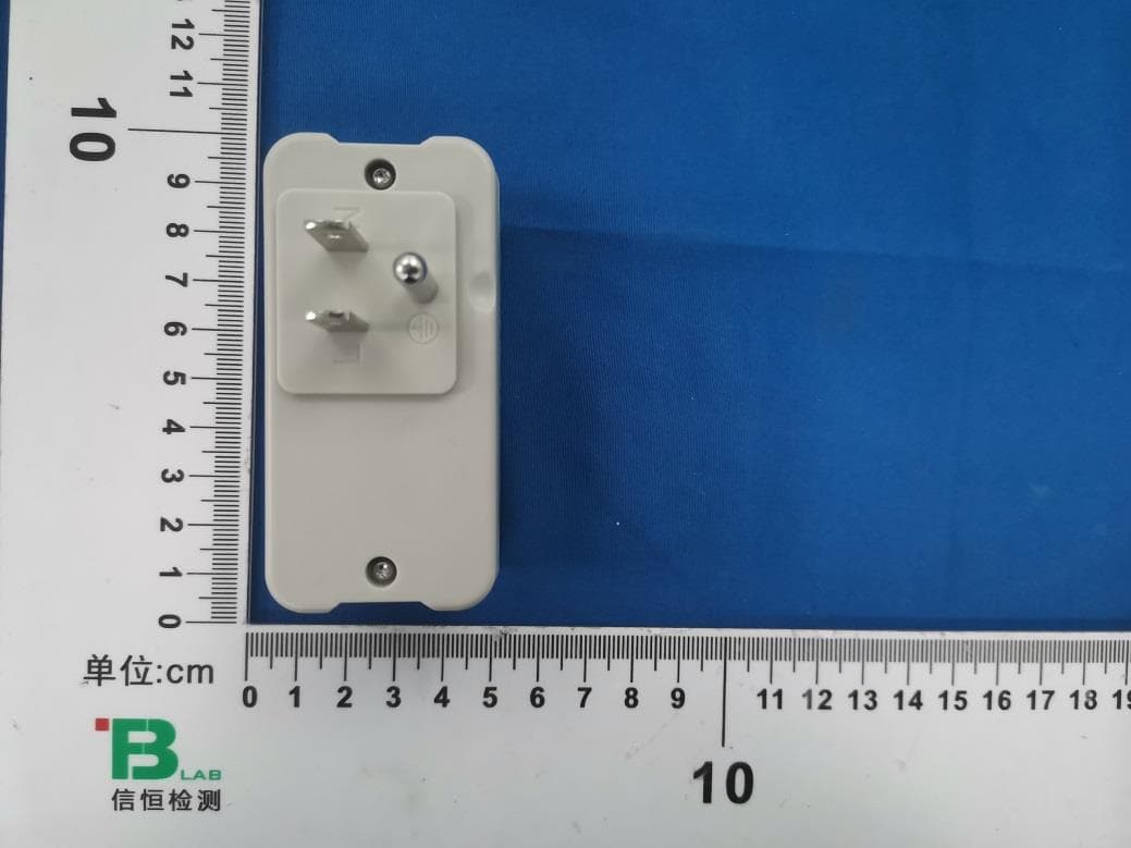
OGUVER5810
Jul 21, 2024BLE Dual band plug-in sensor
Equipment Class
NII - Unlicensed National Information Infrastructure TX
OGU722022
Oct 05, 2022Clearview BLE/IR Badge
Equipment Class
DTS - Digital Transmission System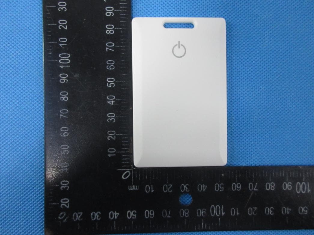
OGU702022
May 06, 2022BLE Badge
Equipment Class
DTS - Digital Transmission System
OGUVER3522
Apr 05, 2015Event Tag
Equipment Class
DSC - Part 15 Security/Remote Control Transmitter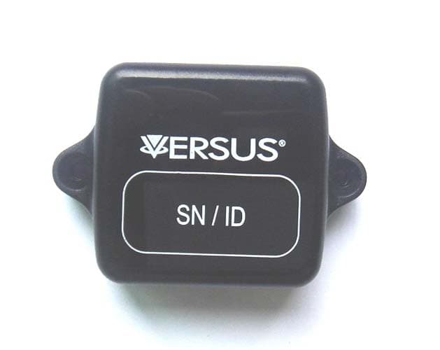
OGUVER188X
Sep 02, 2014MiniAssetTag
Equipment Class
DSC - Part 15 Security/Remote Control Transmitter