OGUVER3500PAS Transmitter
Midmark RTLS Solutions, Inc.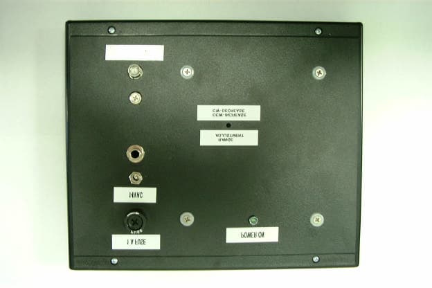
Click to zoom
Application Details
- Equipment Class
- DCD - Part 15 Low Power Transmitter Below 1705 kHz
- Date of Grant
- Aug 07, 2001
- Application Purpose
- Original Equipment
- Date of Application
- Aug 07, 2001
- Equipment Note
- PAS Transmitter
- Frequency Range
- 0.01070000 - 0.01070000
- Company
- Midmark RTLS Solutions, Inc.
- Country
- United States
Documents & Files
Document Text
Text extracted from the exhibit documents filed with the FCC. Open a document above to read the original.
Users Manual
Copyright 1991, 1992, 1993, 1996, 1998, and 2000 Versus Technology, Inc., all rights reserved. This document contains user’s information on technology that is proprietary to Versus Technology, Inc. Permitted transmittal, receipt, or possession of this document does not express license or imply any rights to use, sell, design, or manufacture this information. No reproduction, publication or disclosure of this information, in whole or in part, shall be made without prior written authorization from an officer of Versus Technology, Inc. WARNING! This product is not designed, intended, authorized or warranted for use in any life support or other application where product failure could cause or contribute to personal injury, death, or severe property damage. This product or its systems are covered by one or more of the following U.S. Patents: 4,906,853; 5,017,794; 5,027,314; 5,119,104; 5,276,496; 5,355,222; 5,387,993; 5,548,637; 5,572,195, 6,104,295. FCC STATEMENT: Components complying with part 15 of the FCC Rules – Operation is subject to the following two conditions: 1) This device may not cause harmful interference, and 2) this device must accept any interference received, including interference that may cause undesired operation. Modifying or tampering with the transceiver’s or receiver’s internal components can cause a malfunction, invalidate the warranty, and will void your FCC authorization to use these products. Revision date: 1/29/2001 Contents 1. Introduction.......................................................................................................................1 1.1 System Overview......................................................................................................1 1.2 Terms and Definitions...............................................................................................1 1.3 Parts List...................................................................................................................2 2. Eagle Eye Direct Hardware Components.........................................................................3 2.1 Readers....................................................................................................................3 2.1.1 IR Reader.......................................................................................................3 2.1.2 RF Reader......................................................................................................3 2.2 Tags.........................................................................................................................3 2.2.1 A Discussion about Active Tags......................................................................3 2.2.2 IR Tags...........................................................................................................4 2.2.3 RF Tags.........................................................................................................4 2.2.4 IR/RF Tags.....................................................................................................4 2.3 Perimeter Alarm Sentinel (PAS)................................................................................5 2.4 Eagle Eye Direct Controller Board.............................................................................6 3. Planning and Installation Guidelines...............................................................................7 3.1 Reader Location Planning.........................................................................................7 3.1.1 Reader Connection Length Limitations............................................................7 3.1.2 Cable Types...................................................................................................7 3.1.3 Infrared (IR) Reader Field-of-View...................................................................7 3.1.4 Special Situations with IR Reader Locations...................................................7 3.1.5 RF Reader Location Planning.........................................................................8 3.2 Safety and Code Considerations...............................................................................8 3.2.1 Equipment Handling........................................................................................8 3.2.2 Codes and Ratings of Materials Used.............................................................9 3.2.3 Workmanship..................................................................................................9 4. Component Installation...................................................................................................10 4.1 Cable Installation......................................................................................................10 4.2 Reader Installation...................................................................................................10 4.3 Controller Board Configuration.................................................................................11 4.3.1 Terminal Strip Connections............................................................................12 4.3.2 Momentary Push-Button Switches..................................................................13 4.3.3 LED Indicators...............................................................................................14 4.3.4 DIP Switch Settings.......................................................................................15 4.4 Perimeter Alarm Sentinel Installation........................................................................17 4.4.1 Special considerations for installing the PAS unit...........................................17 4.4.2 Range Adjustment.........................................................................................17 Eagle Eye Direct 1 1. INTRODUCTION 1.1 System Overview Eagle Eye Direct is a system that allows you to use Versus Technology’s Active Radio Frequency (RF) Identification tags and Versus Technol…
Text truncated - open the document above for the full version.
Cover Letter(s)
1 Versus Technology, Inc. would like product description, block diagram and the schematic held confidential for the VER-3500. Regards, Robert Wiser Vers us Tec hnology Engi neer 1 2600 Miller Creek Road Traverse City, MI 49684 Phone: (616-946-5868) Fax: (616-946-6775)
Contact Information
Applicant
Robert Wiser(Design Engineer)
Non-Technical Contact
Versus TechnologyHenery Tenarvitz
[email protected]1 231 946 5868
Test Firm
Elite Electronic Engineering Co.Daniel Crowder
Technical Specifications
| # | Rule Parts | Frequency Range | Power Output |
|---|---|---|---|
| 1 | 15C | 0.0107 MHz - 0.0107 MHz | - |
Other Applications from Midmark RTLS Solutions, Inc.
OGUVER5810
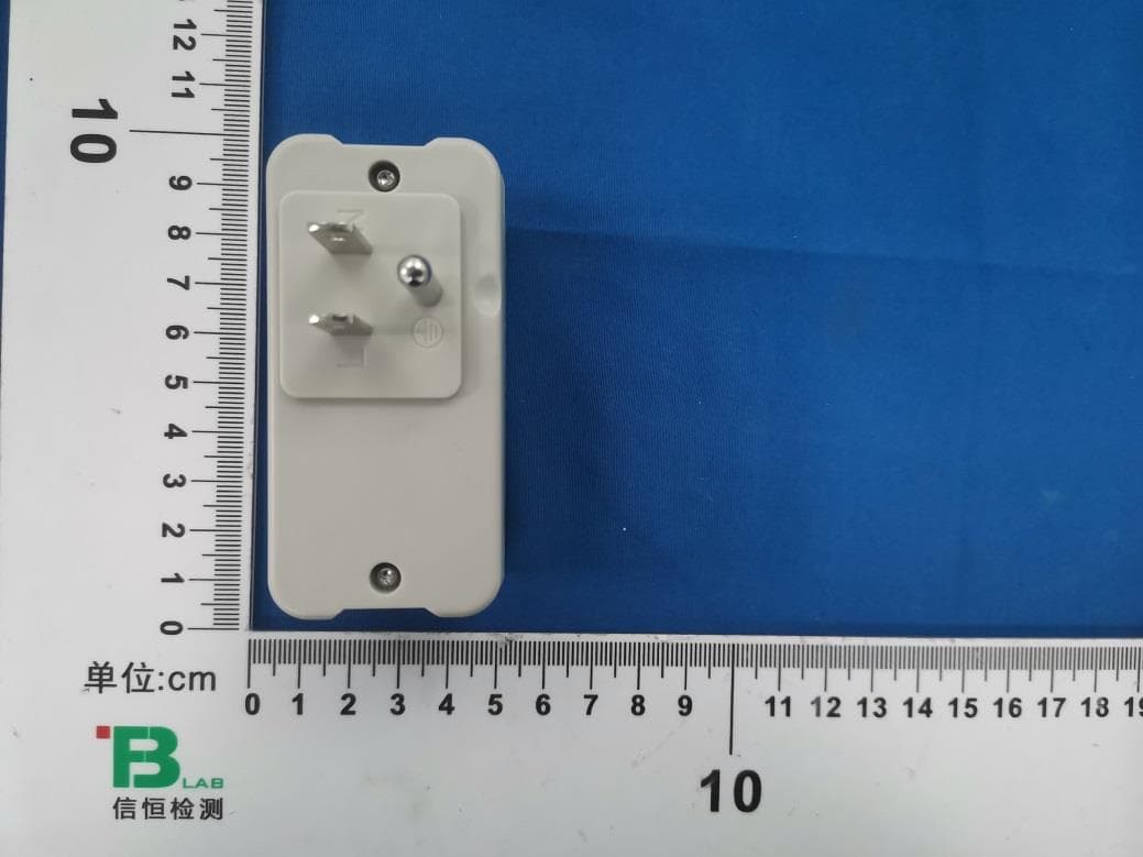
Jul 21, 2024BLE Dual band plug-in sensor
Equipment Class
NII - Unlicensed National Information Infrastructure TX
OGU722022
Oct 05, 2022Clearview BLE/IR Badge
Equipment Class
DTS - Digital Transmission System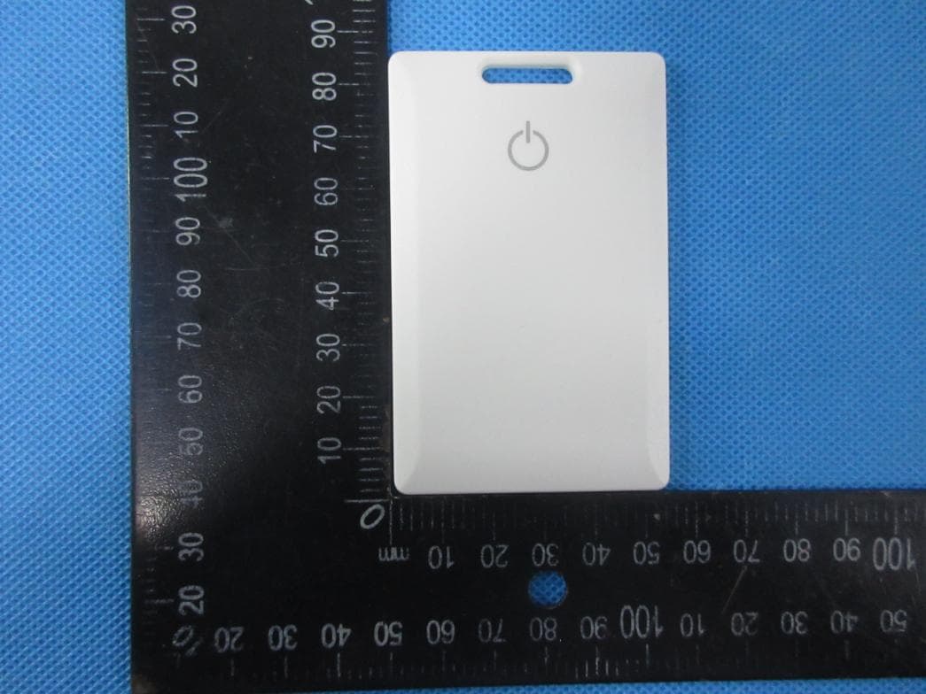
OGU702022
May 06, 2022BLE Badge
Equipment Class
DTS - Digital Transmission System
OGUVER3522
Apr 05, 2015Event Tag
Equipment Class
DSC - Part 15 Security/Remote Control Transmitter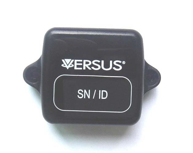
OGUVER188X
Sep 02, 2014MiniAssetTag
Equipment Class
DSC - Part 15 Security/Remote Control Transmitter