OGUVER4070CRemote Station with Jack
Midmark RTLS Solutions, Inc.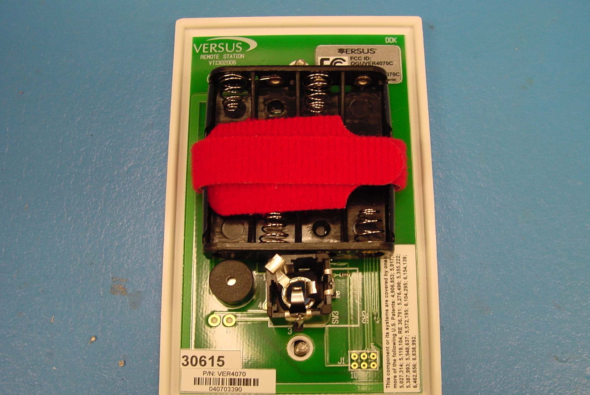
Click to zoom
Application Details
- Equipment Class
- DSC - Part 15 Security/Remote Control Transmitter
- Date of Grant
- Aug 02, 2010
- Application Purpose
- Original Equipment
- Date of Application
- Aug 02, 2010
- Equipment Note
- Remote Station with Jack
- Frequency Range
- 433.90000000 - 433.90000000
- Company
- Midmark RTLS Solutions, Inc.
- Country
- United States
Documents & Files
Document Text
Text extracted from the exhibit documents filed with the FCC. Open a document above to read the original.
Users Manual
Versus Information System User Guide V ERSUS TECHNOLOGY, INC. 2600 MILLER CREEK ROAD T RAVERSE CITY, MI 49684 (231) 946-5868 www.versustech.com i Copyright 1991 – 2006 Versus Technology, Inc., all rights reserved. This document contains user’s information on technology that is proprietary to Versus Technology, Inc. Permitted transmittal, receipt, or possession of this document does not express license or imply any rights to use, sell, design, or manufacture this information. No reproduction, publication or disclosure of this information, in whole or in part, shall be made without prior written authorization from an officer of Versus Technology, Inc. WARNING! This product is not designed, intended, authorized or warranted for use in any life support or other application where product failure could cause or contribute to personal injury, death, or severe property damage. This product or its systems are covered by one or more of the following U.S. Patents: 4,906,853; 5,017,794; 5,027,314; 5,119,104; 5,276,496; 5,548,637; 5,572,195; 5,355,222; 5,387,993; 6,104,295; 6,154,139; 6,838,992. Note: Versus Information Systems (VIS™) VIS uses patented infrared and radio frequency technology to deliver precise location-specific information. VIS is marketed directly to medical facilities and through a network of authorized distributors. Because Versus Technology, Inc. is constantly improving its products, specifications within all Versus manuals are subject to change without notice. Revision date: September 2006 Proprietary Information – Do Not Distribute FCC STATEMENT: Components complying with part 15 of the FCC Rules. Operation is subject to the following two conditions: 1) This device may not cause harmful interference, and 2) this device must accept any interference received, including interference that may cause undesired operation. Modifying or tampering with the transceiver’s or receiver’s internal components can cause a malfunction, invalidate the warranty, and will void your FCC authorization to use these products. Contents 1. Introduction ...........................................................................................................................3 1.1 Purpose of This Guide ..................................................................................................3 1.2 Computer Requirements ...............................................................................................3 1.2.1 Server Computer Requirements ......................................................................4 1.2.2 Computer Workstation Requirements Including Relay Controlled Devices ....4 1.3 Terms and Definitions ...................................................................................................5 1.4 Versus Hardware Parts List ..........................................................................................6 2. System Description ..............................................................................................................7 2.1 Infrared (IR) Tracking ....................................................................................................7 2.2 Radio Frequency (RF) Signals......................................................................................7 2.3 System Hardware Components ....................................................................................8 2.3.1 Badges .............................................................................................................8 2.3.2 Sensors ..........................................................................................................11 2.3.3 Collectors .......................................................................................................12 2.3.4 Ethernet Concentrators ..................................................................................12 2.3.5 Optional Hardware .........................................................................................12 Versus Technology, Inc. 3 1. Introduction 1.1 Purpose of This Guide This document is intended to provide information about the components of a Versus Information Systems (VIS TM ) system. Read this entire document before proceeding with the installation. A general understanding of wiring and telephone installation techniques is assumed. 1.2 Computer Requirements The VIS software runs in the Microsoft Windows 2000 or XP environments and requires a computer system with reasonable capacity and speed. Versus Technology, Inc. 4 1.2.1 Server Computer Requirements The minimum computer requirement for the server computer running the Data Server, Badge Server, and Configuration Utilities are as follows: Operating System Windows 2000 or XP, Pro or Server version recommended Processor Current shipping model or better Memory 512 MB RAM or more, depending on operating system Hard drive 40 GB or equivalent 2 nd Hard Drive 40 GB hard drive for purpose of redundancy Floppy Disk Drive 3.5 1.44 MB CD-ROM 48X CD-ROM or better, CD-RW optional Sound Card Standard sound card or better (optional) Speakers Standard Speakers (optional) Network Card Standard Ethernet Card Modem 56K Data/Fax Modem (optional) Tape Backup 10/20GB, SCSI, Travan-5 or Equivalent (recommended) UPS UPS recommended These are minimums only; additional resources may be needed depending on the size of the system. 1.2.2 Computer Workstation Requirements Including Relay Controlled Devices As part of the Versus System, relay-controlled devices (such as corridor lights) can be connected to relay boards, which are then connected to a computer that contains a relay control board. The computer that contains the relay control board will also have the Relay Control software installed for configuring the relays. The computer requires a PCI slot for the PCI-DIO96H relay controller card. One PCI-DIO96H relay controller card can have two CIO-ERB48 relay boards connected to it. One workstation can have up to five PCI-DIO96H relay controller cards in…
Text truncated - open the document above for the full version.
Cover Letter(s)
FCC ID: OGUVER4070C Request for Confidentiality In accordance with 47 C.F.R. Section 0.459, we, (Versus Technology, Inc.), hereby request confidentiality for the block diagram, schematic and product description presented for certification. In support of the Request for Confidentiality, the following is stated: Enclosed within this application is technical information which we deem to be trade secrets and proprietary. If made public, the information might be used to our disadvantage. To assist in assuring that we receive the full value of our product and protect its competitive posture, we respectfully request this grant of confidentiality. Robert Wiser Versus Technology, Inc.
Test Report
Engineering Test Report No. 1001178-03 Measurement of RF Interference from a Model VER4070(c) Remote Station TS Transmitter For : Versus Technology, Inc. 2600 Miller Creek Road Traverse City, MI 49684 P.O. No. : RLW-01391 Date Tested : April 23, 2010 through May 21, 2010 Test Personnel : Richard King Specification : FCC "Code of Federal Regulations" Title 47 Part 15, Subpart C : Industry Canada RSS-210 : Industry Canada RSS-GEN Test Report By : Richard King EMC Engineer Witnessed by : Bob Wiser Versus Technology, Inc. Approved By : Raymond J. Klouda Registered Professional Engineer of Illinois - 44894 Elite Electronic Engineering Inc. 1516 Centre Circle Downers Grove, IL 60515 Tel : (630) 495-9770 Fax: (630) 495-9785 www.elitetest.com Engineering Test Report No. 1001178-03 TABLE OF CONTENTS PARAGRAPH DESCRIPTION OF CONTENTS PAGE NO. THIS REPORT SHALL NOT BE REPRODUCED, EXCEPT IN FULL, WITHOUT THE WRITTEN APPROVAL OF ELITE ELECTRONIC ENGINEERING INCORPORATED. Page 2 of 25 1 INTRODUCTION .......................................................................................................................................... 4 1.1 Scope of Tests ..................................................................................................................................... 4 1.2 Purpose ............................................................................................................................................... 4 1.3 Deviations, Additions and Exclusions .................................................................................................. 4 1.4 EMC Laboratory Identification ............................................................................................................. 4 1.5 Laboratory Conditions.......................................................................................................................... 4 2 APPLICABLE DOCUMENTS ....................................................................................................................... 4 3 TEST ITEM SETUP AND OPERATION ....................................................................................................... 4 3.1 General Description ............................................................................................................................. 4 3.1.1 Power Input ..................................................................................................................................... 5 3.1.2 Peripheral Equipment ...................................................................................................................... 5 3.1.3 Interconnect Cables ........................................................................................................................ 5 3.1.4 Grounding ........................................................................................................................................ 5 3.2 Operational Mode ................................................................................................................................ 5 3.3 Test Item Modifications ........................................................................................................................ 5 4 TEST FACILITY AND TEST INSTRUMENTATION ..................................................................................... 5 4.1 Shielded Enclosure .............................................................................................................................. 5 4.2 Test Instrumentation ............................................................................................................................ 5 4.3 Calibration Traceability ........................................................................................................................ 5 4.4 Measurement Uncertainty ................................................................................................................... 5 5 TEST PROCEDURES .................................................................................................................................. 6 5.1 Powerline Conducted Emissions ......................................................................................................... 6 5.1.1 Requirements .................................................................................................................................. 6 5.2 Periodic Operation Measurements ...................................................................................................... 6 5.2.1 Requirements .................................................................................................................................. 6 5.2.2 Procedures ...................................................................................................................................... 6 5.2.3 Results............................................................................................................................................. 7 5.3 Duty Cycle Factor Measurements ....................................................................................................... 7 5.3.1 Procedures ...................................................................................................................................... 7 5.3.2 Results............................................................................................................................................. 7 5.4 Radiated Measurements ..................................................................................................................... 8 5.4.1 Requirements .................................................................................................................................. 8 5.4.2 Procedures ...................................................................................................................................... 8 5.4.3 Results..................................................................…
Text truncated - open the document above for the full version.
Test Setup Photos
Engineering Test Report No. 1001178-03 Page 13 of 25 Figure 2 Test Setup for Radiated Emissions – Horizontal Polarity Test Setup for Radiated Emissions – Vertical Polarity
Contact Information
Applicant
Robert Wiser(Design Engineer)
Non-Technical Contact
Versus TechnologyHenry J Tenarvitz
[email protected]2319465868
Test Firm
Elite Electronic Engineering Inc.Kevin Halpin
Technical Specifications
| # | Rule Parts | Frequency Range | Power Output |
|---|---|---|---|
| 1 | 15.231,15.231(e) | 433.9 MHz - 433.9 MHz | - |
Other Applications from Midmark RTLS Solutions, Inc.
OGUVER5810
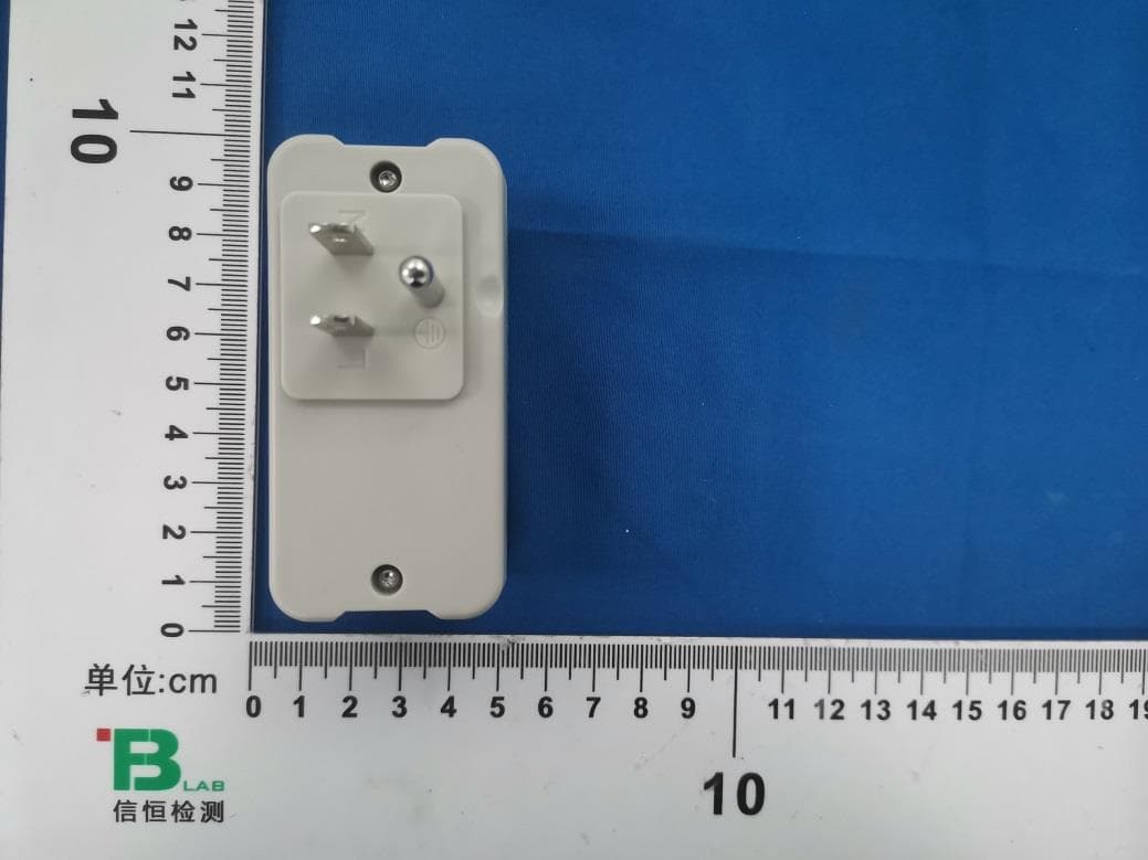
Jul 21, 2024BLE Dual band plug-in sensor
Equipment Class
NII - Unlicensed National Information Infrastructure TX
OGU722022
Oct 05, 2022Clearview BLE/IR Badge
Equipment Class
DTS - Digital Transmission System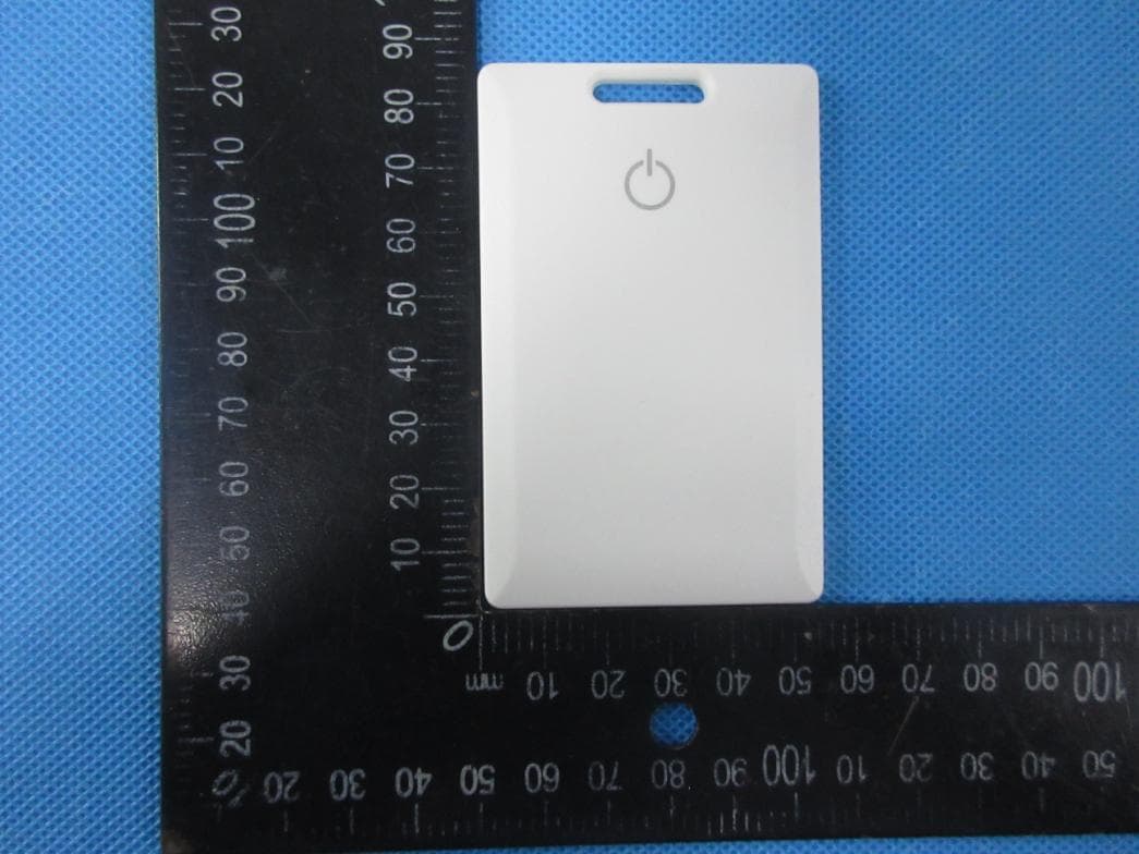
OGU702022
May 06, 2022BLE Badge
Equipment Class
DTS - Digital Transmission System
OGUVER3522
Apr 05, 2015Event Tag
Equipment Class
DSC - Part 15 Security/Remote Control Transmitter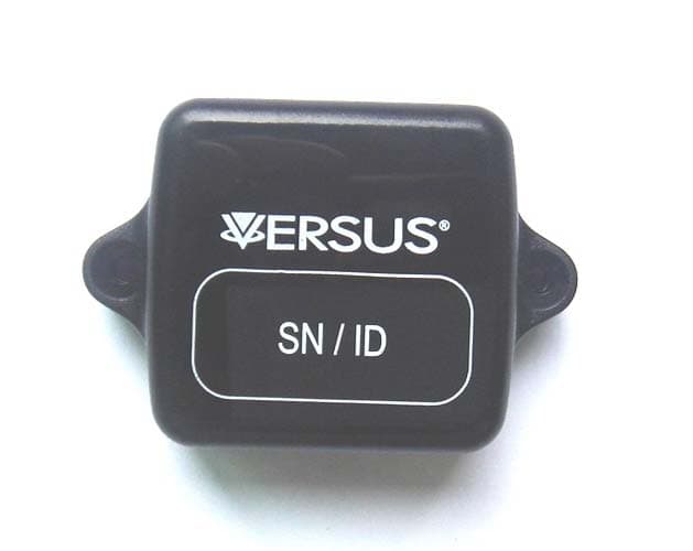
OGUVER188X
Sep 02, 2014MiniAssetTag
Equipment Class
DSC - Part 15 Security/Remote Control Transmitter