OH23160Personal Pump Communicator
Medtronic MiniMed, Inc.
Click to zoom
Application Details
- Equipment Class
- DXT - Part 15 Low Power Transceiver, Rx Verified
- Date of Grant
- Jul 29, 2004
- Application Purpose
- Original Equipment
- Date of Application
- Jul 29, 2004
- Equipment Note
- Personal Pump Communicator
- Frequency Range
- 0.13300000 - 0.13300000
- Company
- Medtronic MiniMed, Inc.
- Country
- United States
Documents & Files
Document Text
Text extracted from the exhibit documents filed with the FCC. Open a document above to read the original.
Users Manual
English ** NOTE **Please refer to the physician and patient manuals for detailed instructions for use and information regarding the Medtronic MiniMed Implantable Insulin Pump System MMT-2007DImplantable Insulin Pump MMT-3150Personal Pump Communicator MMT-4024Infusion Catheter, 10.2 cm MMT-4027Infusion Catheter, 17.8 cm MMT-4102Refill Needle MMT-4104100 μl Pipette MMT-4105Refill Kit MMT-4106Refill Template MMT-4116Holster MMT-4117Clinician Software MMT-4118Link Cable DESCRIPTION The Medtronic MiniMed Implantable Insulin Pump System ("MIP System") is a programmable medical device, designed to administer insulin for the treatment of Type 1 or insulin- requiring Type 2 diabetes mellitus. The Implantable Insulin Pump ("Pump") and Infusion Catheter are fully implanted. The Personal Pump Communicator ("PPC") is a hand-held controller, used to program the Pump and receive Pump information via RF telemetry (wireless). Accessories are also provided to diagnose, maintain and refill the MIP System. The Refill Needle and Refill Kit are used to remove unused insulin and then refill the Pump with insulin every 2-3 months, and to perform in situ Pump rinsing and catheter flushing procedures. The 100 μl Pipette is used to verify Pump stroke volume prior to implantation. The Refill Template is used to locate and align the Pump fill port and side port during a refill, Pump rinsing or catheter flushing procedures. The Holster allows the PPC to be worn on a belt. The Link Cable is used to transfer data from the PPC to the physician's computer. The Clinician Software is utilized in the physician's computer to prepare a data report. INDICATIONS AND USAGE The MIP System is indicated for the long-term, continuous, intraperitoneal administration of exogenous insulin, to maintain glycemic control in patients with Type 1 or insulin-requiring Type 2 diabetes mellitus. In order for the insulin therapy to be efficacious, patients must actively participate in their Pump treatment program. CONTRAINDICATIONS • Patients unwilling or unable to: * Test their blood glucose (BG) four or more times per day * Use their BG results to update Pump programming * Switch to subcutaneous insulin injections, if their Pump fails * Comply with the guidance of their primary care physician * Return to their physician every 2-3 months for insulin refills • Patients who reside or travel above 8,000 ft. (2,400 m.) elevation • Patients with a history of hypersensitivity reactions to titanium alloy or silicone materials that are used in the MIP System WARNINGS The Pump can only be used with the MMT-3150 PPC and either the MMT-4024 or MMT-4027 Infusion Catheter. The Pump can only be refilled or rinsed using the MMT-4102 Refill Needle and MMT-4105 Refill Kit. Use of other needles may damage the Pump valve and septum. Only Aventis U-400 insulin can be used in the MIP System. Use of other insulins could cause damage to the Pump, resulting in inaccurate insulin delivery or Pump failure. Exposure to therapeutic ultrasound may damage the MIP System. PRECAUTIONS Patients must always have supplies available for taking subcutaneous insulin injections, in the event of a MIP System malfunction. If a malfunction is suspected, patients should immediately discontinue the use of their MIP System, and contact their primary care physician for instructions and MIP System diagnosis. If insulin delivery is impaired, the Pump may need to be rinsed and/or the Infusion Catheter flushed to remove insulin precipitates. If impaired insulin delivery is suspected, patients should immediately contact their primary care physician for instructions and MIP System diagnosis. Physicians should review the Physician's Manual for a full description of pump rinsing, catheter flushing and software reset options to be considered for diagnosing and restoring a failed or impaired MIP System. Physicians must be completely familiar with the function of the MIP System prior to its implantation and use. Patients must be fully trained on how to use the MIP System, and must demonstrate proficiency in programming their PPC and responding to alarms prior to using the MIP System on their own. Individual components of the MIP System should NOT be used if damaged prior to or during the implantation procedure. The Pump should not be placed in direct contact with other metal implants. When refilling the Pump, never push on the syringe plunger. When the Refill Needle is properly seated in the Pump fill port, vacuum in the Pump reservoir will automatically draw in insulin from the syringe. When refilling the Pump, never release the syringe-locking ring while there is a vacuum. The handle of the syringe may snap back forcibly and damage the syringe. When measuring the Pump stroke volume, always check for leaks at the Pump - Pipette connection. If a leak occurs, the measurement is inaccurate and should be repeated. ADVERSE EVENTS Although the safety of the MIP System has been well demonstrated during clinical evaluations spanning more than 10 years, the following adverse events have been reported: Abdominal PainForeign Body Reaction Inflammation at Refill SiteSkin Disorder InfectionUrinary Disorder NecrosisKetoacidosis Retinal DisorderSkin Erosion Abnormal Liver FunctionKidney Disorder IleusPocket Lymph Edema HyperglycemiaCatheter Occlusion/Encapsulation HypoglycemiaAnti-Insulin Antibodies* * A small number of patients may develop elevated titers of anti- insulin antibodies in their bloodstream. Clinical evaluations have shown that elevated anti-insulin antibodies alone do not interfere with the maintenance of glycemic control provided with this treatment. STERILE DEVICE The Pump and Infusion Catheter are sterilized by ethylene oxide and provided in tamper evident packaging. Do not use if the package has been opened or damaged. The MMT-4104 100 μl Pipette and MMT-4106 Refill Template are not supplied sterile. They should be steam sterilized prior to their use. WIRELESS COMMUNICATION NOTICE This device c…
Text truncated - open the document above for the full version.
Users Manual
Medtronic MiniMed 2007D Implantable Insulin Pump System Physician’s Manual © 2003, Medtronic MiniMed. All rights reserved. Medtronic MiniMed™ is a trademark of Medtronic MiniMed Dual Wave™ is a trademark of Medtronic MiniMed Square Wave™ is a trademark of Medtronic MiniMed Steri-strip® is a registered mark from 3M Aventis® is a registered mark from Aventis Pharmaceutical Genapol® is a registered mark from Aventis Pharmaceutical Luer Lok® is a registered mark from BD and Co. This device is protected under one or more of the following U.S. Patents: U.S., international, and foreign patent applications are pending. 4,731,0515,217,4425,527,3076,427,088 4,776,8425,257,9715,559,8286,537,268 5,167,6335,460,6185,797,7336,562,001 5,176,6445,466,2185,915,9296,564,105 5,197,3225,514,1036,283,9436,571,128 6025069-011 7/04 REF MMT-3160 0976 i Table of contents CHAPTER 1Description. . . . . . . . . . . . . . . . . . . . . . . . . . . . 1 Introduction . . . . . . . . . . . . . . . . . . . . . . . . . . . . . . . . . . . . . . . . . . . . . . . . . . . 1 Implantable Insulin Pump . . . . . . . . . . . . . . . . . . . . . . . . . . . . . . . . . . . . . . . . 3 Insulin medication . . . . . . . . . . . . . . . . . . . . . . . . . . . . . . . . . . . . . . . . . . . 5 Side Port Catheter . . . . . . . . . . . . . . . . . . . . . . . . . . . . . . . . . . . . . . . . . . . 6 Personal Pump Communicator (PPC) . . . . . . . . . . . . . . . . . . . . . . . . . . . . 7 CHAPTER 2Indications and contraindications . . . . . . . . . . 9 Indications for use . . . . . . . . . . . . . . . . . . . . . . . . . . . . . . . . . . . . . . . . . . . . . . 9 Contraindications for use . . . . . . . . . . . . . . . . . . . . . . . . . . . . . . . . . . . . . . . . . 9 Possible adverse effects . . . . . . . . . . . . . . . . . . . . . . . . . . . . . . . . . . . . . . . . . 10 CHAPTER 3Personal Pump Communicator (PPC) . . . . . . 11 Introduction . . . . . . . . . . . . . . . . . . . . . . . . . . . . . . . . . . . . . . . . . . . . . . . . . . 11 PPC icons . . . . . . . . . . . . . . . . . . . . . . . . . . . . . . . . . . . . . . . . . . . . . . . . . 11 PPC buttons . . . . . . . . . . . . . . . . . . . . . . . . . . . . . . . . . . . . . . . . . . . . . . . 12 Communicating with the Pump . . . . . . . . . . . . . . . . . . . . . . . . . . . . . . . . 12 Install/Replace the main battery . . . . . . . . . . . . . . . . . . . . . . . . . . . . . . . 13 Part 1: PPC/Pump system initialization . . . . . . . . . . . . . . . . . . . . . . . . . . . . . 15 Initialize the PPC . . . . . . . . . . . . . . . . . . . . . . . . . . . . . . . . . . . . . . . . . . . 15 Set the time and date . . . . . . . . . . . . . . . . . . . . . . . . . . . . . . . . . . . . . . . . 17 Set alarms . . . . . . . . . . . . . . . . . . . . . . . . . . . . . . . . . . . . . . . . . . . . . . . . . 18 Set maximum bolus, basal rate and time display format . . . . . . . . . . 19 Lock maximum bolus/basal, enter personal ID and password, stop Pump . . . . . . . . . . . . . . . . . . . . . . . . . . . . . . . . . . 20 ii Program a basal rate . . . . . . . . . . . . . . . . . . . . . . . . . . . . . . . . . . . . . . . . . 22 Part 2: Additional PPC programming features . . . . . . . . . . . . . . . . . . . . . . . 23 Main menu . . . . . . . . . . . . . . . . . . . . . . . . . . . . . . . . . . . . . . . . . . . . . . . . . . . 23 Program a bolus . . . . . . . . . . . . . . . . . . . . . . . . . . . . . . . . . . . . . . . . . . . . 23 Set a Normal bolus with the Variable Bolus feature turned off . . . . . . . . 24 Set a Normal bolus with the Variable Bolus feature turned on . . . . . . . . 25 Set a Square Wave Bolus . . . . . . . . . . . . . . . . . . . . . . . . . . . . . . . . . . . . . 26 Set a Dual Wave Bolus . . . . . . . . . . . . . . . . . . . . . . . . . . . . . . . . . . . . . . 27 Review bolus history . . . . . . . . . . . . . . . . . . . . . . . . . . . . . . . . . . . . . 28 Suspend mode . . . . . . . . . . . . . . . . . . . . . . . . . . . . . . . . . . . . . . . . . . 29 Programming a basal rate . . . . . . . . . . . . . . . . . . . . . . . . . . . . . . . . . . . . . . . 30 Programming basal delivery pattern . . . . . . . . . . . . . . . . . . . . . . . . . . . . 30 Setting basal rate profiles in each delivery pattern . . . . . . . . . . . . . . . . . 31 Program a temporary basal rate . . . . . . . . . . . . . . . . . . . . . . . . . . . . . . . . 32 Set a temporary basal rate . . . . . . . . . . . . . . . . . . . . . . . . . . . . . . . . . . . . 32 Stop a temporary basal rate . . . . . . . . . . . . . . . . . . . . . . . . . . . . . . . . . . . 33 Personal events . . . . . . . . . . . . . . . . . . . . . . . . . . . . . . . . . . . . . . . . . . . . . . . 34 History . . . . . . . . . . . . . . . . . . . . . . . . . . . . . . . . . . . . . . . . . . . . . . . . . . . 35 Setup Pump . . . . . . . . . . . . . . . . . . . . . . . . . . . . . . . . . . . . . . . . . . . . . . . . . . 37 Time and Date . . . . . . . . . . . . . . . . . . . . . . . . . . . . . . . . . . . . . . . . . . . . . 37 Auto off . . . . . . . . . . . . . . . . . . . . . . . . . . . . . . . . . . . . . . . . . . . . . . . . . . 37 Alarms . . . . . . . . . . . . . . . . . . . . . . . . . . . . . . . . . . . . . . . . . . . . . . . . . . . 38 Self test . . . . . . . . . . . . . . . . . . . . . . . . . . . . . . . . . . . . . . . . . . . . . . . . . . 38 Basal delivery pattern . . . . . . . . . . . . . . . . . . . . . . . . . . . . . . . . . . . . . . . 39 Initialize PPC to Pump . . . . . . . . . . . . . . . . . . . . . . . . . . . . . . . . . . . . . . . 39 Setup II . . . . . . . . . . . . . . . . . . . . . . . . . . . . . . . . . . . . . . . . . . . . . . . . . . . 39 Exit Setup menu . . . . . . . . . . . . . . . . . . . . . . . . . . . . . . . . . . . . . . . . . . . . 39 Setup II . . . . . . . . . . . . . . . . . . . . . . . . . . . . . . . . . . . . . . . . . . . . . . . . . . . . . . 40…
Text truncated - open the document above for the full version.
Users Manual
Medtronic MiniMed 2007D Implantable Insulin Pump System Patient Manual © 2003, Medtronic MiniMed. All rights reserved. Medtronic MiniMed™ is a trademark of Medtronic MiniMed Dual Wave™ is a trademark of Medtronic MiniMed Square Wave™ is a trademark of Medtronic MiniMed Steri-strip® is a registered mark from 3M Aventis® is a registered mark from Aventis Pharmaceutical Genapol® is a registered mark from Aventis Pharmaceutical Luer Lok® is a registered mark from BD and Co. This device is protected under one or more of the following U.S. Patents: U.S., international, and foreign patent applications are pending. 4,731,0515,217,4425,527,3076,427,088 4,776,8425,257,9715,559,8286,537,268 5,167,6335,460,6185,797,7336,562,001 5,176,6445,466,2185,915,9296,564,105 5,197,3225,514,1036,283,9436,571,128 6025070-011 7/04 REF MMT-3160 0976 i Table of contents CHAPTER 1The Medtronic MiniMed 2007D Implantable Insulin Pump System . . . . . . . . . . . . . . . . . . . . 1 Introduction . . . . . . . . . . . . . . . . . . . . . . . . . . . . . . . . . . . . . . . . . . . . . . . . . . . 1 Medtronic MiniMed help line . . . . . . . . . . . . . . . . . . . . . . . . . . . . . . . . . . . . . 1 Description of the system . . . . . . . . . . . . . . . . . . . . . . . . . . . . . . . . . . . . . . . . 2 Medication reservoir . . . . . . . . . . . . . . . . . . . . . . . . . . . . . . . . . . . . . . 3 Pumping mechanism . . . . . . . . . . . . . . . . . . . . . . . . . . . . . . . . . . . . . . 3 Antenna . . . . . . . . . . . . . . . . . . . . . . . . . . . . . . . . . . . . . . . . . . . . . . . . 3 Microelectronics . . . . . . . . . . . . . . . . . . . . . . . . . . . . . . . . . . . . . . . . . 3 Battery . . . . . . . . . . . . . . . . . . . . . . . . . . . . . . . . . . . . . . . . . . . . . . . . . 4 Tone transducer . . . . . . . . . . . . . . . . . . . . . . . . . . . . . . . . . . . . . . . . . . 4 Side Port Catheter . . . . . . . . . . . . . . . . . . . . . . . . . . . . . . . . . . . . . . . . . . . 4 Personal Pump Communicator (PPC) . . . . . . . . . . . . . . . . . . . . . . . . . . . . 5 Special insulin . . . . . . . . . . . . . . . . . . . . . . . . . . . . . . . . . . . . . . . . . . . . . . 6 CHAPTER 2Safety features . . . . . . . . . . . . . . . . . . . . . . . . . 7 Pump safety features . . . . . . . . . . . . . . . . . . . . . . . . . . . . . . . . . . . . . . . . . . . . 7 Safe telemetry . . . . . . . . . . . . . . . . . . . . . . . . . . . . . . . . . . . . . . . . . . . . . . 7 Alarms . . . . . . . . . . . . . . . . . . . . . . . . . . . . . . . . . . . . . . . . . . . . . . . . . . . . 7 Negative pressure reservoir . . . . . . . . . . . . . . . . . . . . . . . . . . . . . . . . . . . . 7 PPC safety features . . . . . . . . . . . . . . . . . . . . . . . . . . . . . . . . . . . . . . . . . . . . . 8 Programming sequence . . . . . . . . . . . . . . . . . . . . . . . . . . . . . . . . . . . . . . . 8 Maximum dosage limits . . . . . . . . . . . . . . . . . . . . . . . . . . . . . . . . . . . . . . . 8 Table of contents ii Alarms and messages . . . . . . . . . . . . . . . . . . . . . . . . . . . . . . . . . . . . . . . . . 8 CHAPTER 3Implanting the Medtronic MiniMed 2007D Pump System. . . . . . . . . . . . . . . . . . . . . 9 Hospitalization . . . . . . . . . . . . . . . . . . . . . . . . . . . . . . . . . . . . . . . . . . . . . . . . . 9 Pre-operative procedures . . . . . . . . . . . . . . . . . . . . . . . . . . . . . . . . . . . . . . 9 Implantation procedures . . . . . . . . . . . . . . . . . . . . . . . . . . . . . . . . . . . . . 10 Post-operative procedures . . . . . . . . . . . . . . . . . . . . . . . . . . . . . . . . . . . . 10 Follow-up . . . . . . . . . . . . . . . . . . . . . . . . . . . . . . . . . . . . . . . . . . . . . . 11 Pump refills . . . . . . . . . . . . . . . . . . . . . . . . . . . . . . . . . . . . . . . . . . . . . . . . . . 11 Insulin used with the Implantable Pump . . . . . . . . . . . . . . . . . . . . . . . . . 11 Pump refill procedure . . . . . . . . . . . . . . . . . . . . . . . . . . . . . . . . . . . . . . . 11 CHAPTER 4Programming your Pump . . . . . . . . . . . . . . . . 13 Introduction . . . . . . . . . . . . . . . . . . . . . . . . . . . . . . . . . . . . . . . . . . . . . . . . . . 13 PPC screen icons . . . . . . . . . . . . . . . . . . . . . . . . . . . . . . . . . . . . . . . . . . . . . . 14 PPC buttons . . . . . . . . . . . . . . . . . . . . . . . . . . . . . . . . . . . . . . . . . . . . . . . . . . 15 Communicating PPC . . . . . . . . . . . . . . . . . . . . . . . . . . . . . . . . . . . . . . . . . . . 15 Main programming screen . . . . . . . . . . . . . . . . . . . . . . . . . . . . . . . . . . . . . . . 16 Programming a bolus . . . . . . . . . . . . . . . . . . . . . . . . . . . . . . . . . . . . . . . . 16 Set an immediate bolus (Variable Bolus option is “off”) . . . . . . . . . . . . . 17 Set an immediate bolus (Variable Bolus option is “on”) . . . . . . . . . . . . . 18 Set a Square Wave bolus . . . . . . . . . . . . . . . . . . . . . . . . . . . . . . . . . . . . . 19 Set a Dual Wave bolus . . . . . . . . . . . . . . . . . . . . . . . . . . . . . . . . . . . . . . . 21 Review the bolus history . . . . . . . . . . . . . . . . . . . . . . . . . . . . . . . . . . . . . 22 Suspend mode . . . . . . . . . . . . . . . . . . . . . . . . . . . . . . . . . . . . . . . . . . . . . 23 Program basal rates . . . . . . . . . . . . . . . . . . . . . . . . . . . . . . . . . . . . . . . . . 23 Set one basal rate . . . . . . . . . . . . . . . . . . . . . . . . . . . . . . . . . . . . . . . . 23 Set multiple basal rates . . . . . . . . . . . . . . . . . . . . . . . . . . . . . . . . . . . 25 Set a temporary basal rate . . . . . . . . . . . . . . . . . . . . . . . . . . . . . . . . . 26 Table of contents iii Stop a temporary basal rate . . . . . . . . . . . . . . . . . . . . . . . . . . . . . . . . 27 Personal events . . . . . . . . . . . . . . . . . . . . . . . . . . . …
Text truncated - open the document above for the full version.
Cover Letter(s)
81943 The EUT meets the requirements for FCC Part 15.203 because it has an integral antenna.
External Photos
Front Back Top Bottom Side
ID Label/Location Info
FCC Label
Internal Photos
Inside Case PCB Front PCB Back LCD Front LCD Back
Operational Description
This document contains information, which is the property of Medtronic MiniMed. This document may not, in whole or in part, be duplicated, disclosed, or used for design or manufacturing purposes without the prior written permission of Medtronic MiniMed. Save Date Type Document Sheet Ver. June 23, 2004 Z20 ES9313 1 of 43 B SPECIFICATION Doc Desc: MMT-3160 PPC Hardware Design Description Ver. E.C.O. No. Description of Change Prepared By Released By Valid Date A 5-8087 Production Release LT B See ECO LT Approved By: Date Approved By: Varaz Shahmirian Date Reviewed By: David Choy Date Prepared By: Lou Tondino Date Save Date Type Document Sheet Ver. June 23, 2004 Z20 ES9313 2 of 43 B TABLE OF CONTENTS 1.0 PURPOSE............................................................................................................4 2.0 SCOPE................................................................................................................4 3.0 ASSOCIATED DOCUMENTS................................................................................4 4.0 DEFINITIONS AND ABBREVIATIONS...................................................................4 5.0 OVERVIEW..........................................................................................................4 6.0 DETAILED DESIGN DESCRIPTION......................................................................6 6.1 Power..............................................................................................................6 6.2 Power Management.........................................................................................7 6.3 Up-converter....................................................................................................16 6.4 Processor........................................................................................................17 6.5 PLD.................................................................................................................17 6.6 Clock...............................................................................................................18 6.7 Reset..............................................................................................................18 6.8 External Interrupts............................................................................................18 6.9 External RAM...................................................................................................19 6.10 Serial ROM......................................................................................................20 6.11 RF...................................................................................................................21 6.12 External I/O Ports.............................................................................................21 6.13 Keypad............................................................................................................23 6.14 Buzzer.............................................................................................................24 6.15 Vibration Motor.................................................................................................25 6.16 AA Battery Measurement Dummy Load.............................................................25 6.17 LCD Module and Support Circuit.......................................................................25 6.18 EL Backlight.....................................................................................................27 6.19 IrDA Port..........................................................................................................28 6.20 Battery Life......................................................................................................28 6.21 Test Connector.................................................................................................30 6.22 PLD Programming............................................................................................31 7.0 XILINX COOLRUNNER PLD PROGRAMMING......................................................31 8.0 HARDWARE CHANGES AS COMPARED TO MMT315X PPC................................34 9.0 HARDWARE CHANGES INDUCED SOFTWARE CHANGES AS COMPARED TO MMT-315X PPC..........................................................................41 10.0 PC BOARD LAYOUT............................................................................................42 Figure 1: PPC Block Diagram.......................................................................................5 Figure 2: MMT3160 PPC Bottom View..........................................................................42 Figure 3: MMT3160 PPC Top Side View........................................................................43 Save Date Type Document Sheet Ver. June 23, 2004 Z20 ES9313 3 of 43 B Table 1: Powers...........................................................................................................7 Table 2: Depleted Battery State.....................................................................................9 Table 3: Other Battery Detector Parameters...................................................................10 Table 4: Hardware VCC Voltage Detector And System Power-Down State.......................11 Table 5 : Power Backup Calculations.............................................................................12 Table 6: Circuit Power Backup Time Calculation.............................................................14 Table 7: Backup Capacitor, SRAM Backup and Circuit Power Backup..............................15 Table 8: Up-Converter..................................................................................................17 Table 9: External Interrupts (IRQs).................................................................................19 Table 10: External SRAM.............................................................................................20 Table 11: Serial EEPROM.......…
Text truncated - open the document above for the full version.
Test Report
Page 1 of 30 Report No.: FC04-027 MEDTRONIC MINIMED TEST REPORT FOR THE PERSONAL PUMP COMMUNICATOR, MMT-3160 FCC PART 15 SUBPART C SECTION 15.209 COMPLIANCE DATE OF ISSUE: APRIL 1, 2004 PREPARED FOR: Medtronic MiniMed 18000 Devonshire Street Northridge, CA 91325-1219 PREPARED BY: Mary Ellen Clayton CKC Laboratories, Inc. 5473A Clouds Rest Mariposa, CA 95338 P.O. No.: 4700000378 W.O. No.: 81943 Date of test: March 22-25, 2004 Report No.: FC04-027 This report contains a total of 30 pages and may be reproduced in full only. Partial reproduction may only be done with the written consent of CKC Laboratories, Inc. The results in this report apply only to the items tested, as identified herein. Page 2 of 30 Report No.: FC04-027 TABLE OF CONTENTS Administrative Information .............................................................................................3 Summary of Results .........................................................................................................4 Conditions for Compliance ..............................................................................................4 Approvals .........................................................................................................................4 FCC 15.31(e) Voltage Variation......................................................................................5 FCC 15.33(a) Frequency Ranges Tested .........................................................................5 Eut Operating Frequency .................................................................................................5 Equipment Under Test (EUT) Description ......................................................................5 Equipment Under Test .....................................................................................................5 Peripheral Devices ...........................................................................................................5 Report of Measurements ..................................................................................................6 Table 1: FCC 15.209 Fundamental ......................................................................6 Table 2: FCC 15.209 Six Highest Radiated Emission Levels: 9kHz - 30MHz ...7 Table 3: FCC 15.209 Six Highest Radiated Emission Levels: >1 GHz ..............8 Measurement Uncertainty ................................................................................................9 EUT Setup........................................................................................................................9 Correction Factors............................................................................................................9 Table A: Sample Calculations .............................................................................9 Test Instrumentation and Analyzer Settings ....................................................................10 Spectrum Analyzer Detector Functions ...............................................................10 Peak..........................................................................................................10 Quasi-Peak ...............................................................................................10 Average ....................................................................................................10 EUT Testing.....................................................................................................................11 Radiated Emissions ..............................................................................................11 Appendix A: Test Setup Photograph ...............................................................................12 Photograph Showing Radiated Emissions ...........................................................13 Appendix B: Test Equipment List ...................................................................................14 Appendix C: Measurement Data Sheets ..........................................................................15 Page 3 of 30 Report No.: FC04-027 ADMINISTRATIVE INFORMATION DATE OF TEST: March 22-25, 2004 DATE OF RECEIPT: March 22, 2004 PURPOSE OF TEST: To demonstrate the compliance of the Personal Pump Communicator, MMT-3160 with the requirements for FCC Part 15 Subpart C Section 15.209 devices. TEST METHOD: ANSI C63.4 (1992) MANUFACTURER: Medtronic MiniMed 18000 Devonshire Street Northridge, CA 91325-1219 REPRESENTATIVE: Varaz Shahmirian TEST LOCATION: CKC Laboratories, Inc. 5473A Clouds Rest Mariposa, CA 95338 Page 4 of 30 Report No.: FC04-027 SUMMARY OF RESULTS As received, the Medtronic MiniMed Personal Pump Communicator, MMT-3160 was found to be fully compliant with the following standards and specifications: United States ¾ FCC Part 15 Subpart C Section 15.209 ¾ ANSI C63.4 (1992) method FCC Site No. 90477 CONDITIONS FOR COMPLIANCE No modifications to the EUT were necessary to comply. APPROVALS Steve Behm, Director of Engineering Services QUALITY ASSURANCE:TEST PERSONNEL: Joyce Walker, Quality Assurance Administrative Manager Mike Wilkinson, Lab Manager Randy Clark, EMC Engineer Page 5 of 30 Report No.: FC04-027 FCC 15.31(e) Voltage Variations Not applicable to this device because it is battery powered. FCC 15.33(a) Frequency Ranges Tested 15.209 Radiated: 9 kHz – 1000 MHz Eut Operating Frequency The EUT was operating at 133 kHz. EQUIPMENT UNDER TEST (EUT) DESCRIPTION The EUT tested by CKC Laboratories was a production unit. The EUT is a Personal Pump Communicator which operates in conjunction with an implantable insulin pump. EUT is battery operated - tests performed with a fresh battery. EQUIPMENT UNDER TEST Implantable Insulin Pump Manuf: Medtronic MiniMed Model: MMT-2007D Serial: 300067 FCC ID: OH22007C Person…
Text truncated - open the document above for the full version.
Contact Information
Applicant
Jonathan Tabalujan(Sr. Electrical Engineer)
Technical Contact
CKC Laboratories, Inc.Mary Ellen Clayton
[email protected]209-966-5240
5473A Clouds Rest · Mariposa, California · United States
Non-Technical Contact
CKC Laboratories, Inc.Mary Ellen Clayton
[email protected]209-966-5240
Test Firm
CKC Laboratories, Inc.Steve Behm
Technical Specifications
| # | Rule Parts | Frequency Range | Power Output |
|---|---|---|---|
| 1 | 15C | 0.133 MHz - 0.133 MHz | - |
Other Applications from Medtronic MiniMed, Inc.
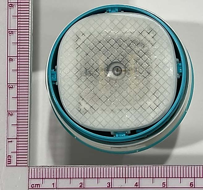
OH2BLEGST2
Jul 08, 2024Disposable glucose sensor transmitter
Equipment Class
DTS - Digital Transmission System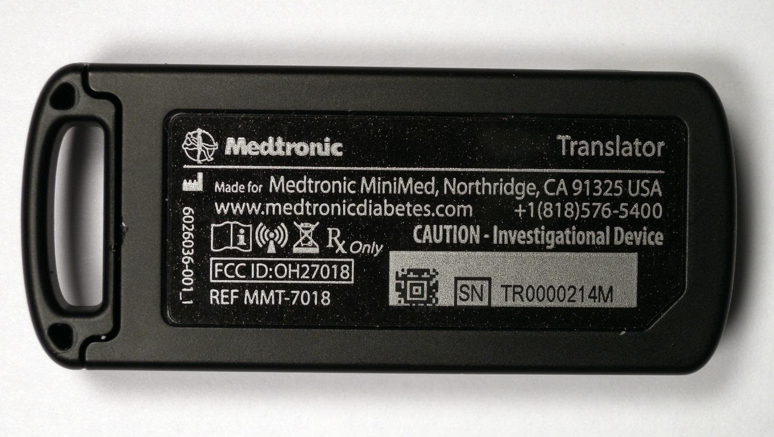
OH27018
Jul 09, 2015The Paradigm Translator allows RF intercommunication between Medtronic Minimed Paradigm series insulin pumps and commercially available smartphones running Medtronic application software.
Equipment Class
DXT - Part 15 Low Power Transceiver, Rx Verified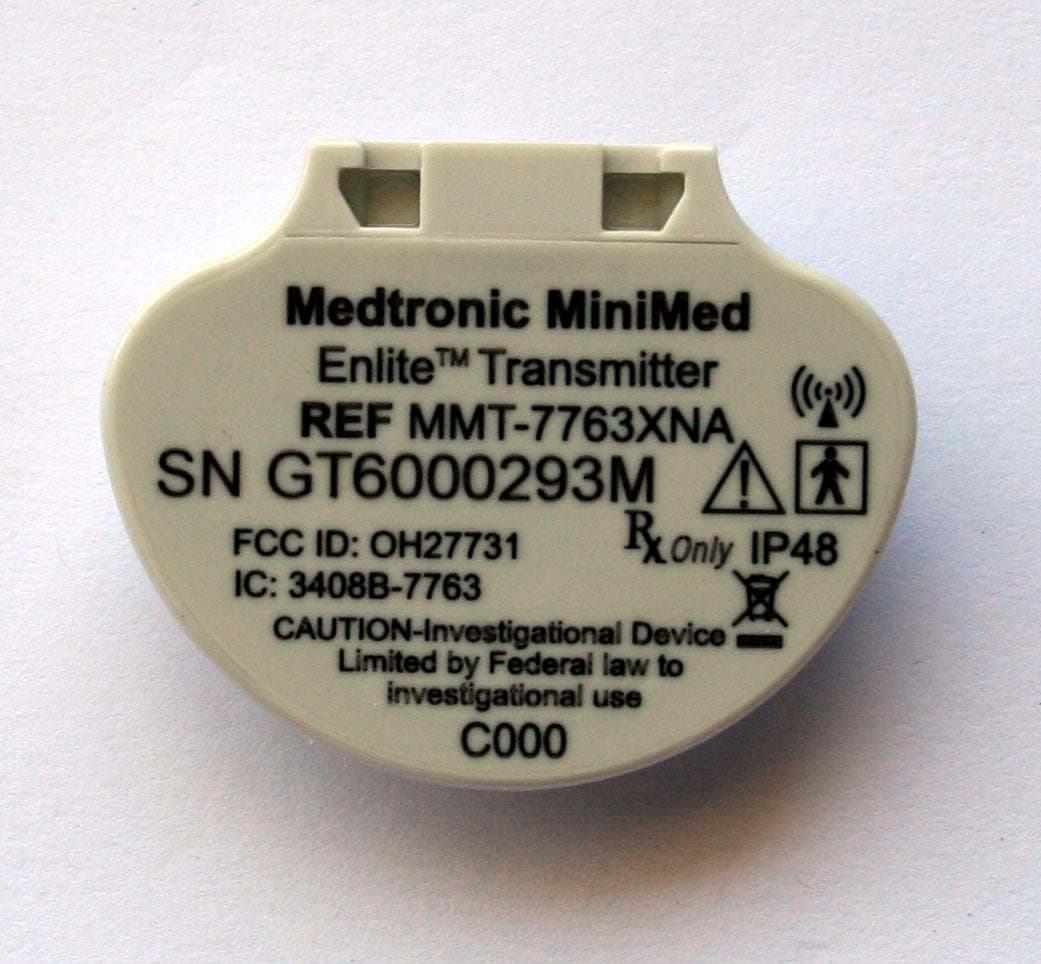
OH27731
Mar 10, 2015The Guardian Link transmitter is a component of the continuous glucose monitoring system for the MiniMed 600 series insulin pumps. The transmitter collects data from the glucose sensor and then wirelessly sends the data to the insulin pump.
Equipment Class
DTS - Digital Transmission System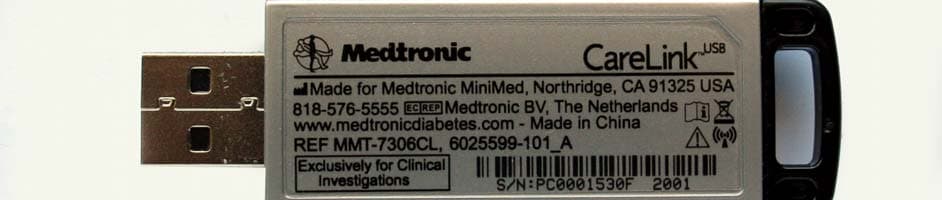
OH27306
Feb 08, 2015CareLINK USB
Equipment Class
DTS - Digital Transmission System
OH21510
Sep 24, 2014620G/630G/640G/670G Insulin Delivery Pump
Equipment Class
DTS - Digital Transmission System