OH2503MiniMed Model 503 Remote Transmitter
Medtronic MiniMed, Inc.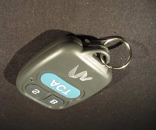
Click to zoom
Application Details
- Equipment Class
- DXX - Part 15 Low Power Communication Device Transmitter
- Date of Grant
- May 01, 2001
- Application Purpose
- Original Equipment
- Date of Application
- May 01, 2001
- Equipment Note
- MiniMed Model 503 Remote Transmitter
- Frequency Range
- 916.50000000 - 916.50000000
- Company
- Medtronic MiniMed, Inc.
- Country
- United States
Documents & Files
Document Text
Text extracted from the exhibit documents filed with the FCC. Open a document above to read the original.
Users Manual
Remote transmitter ACT S B TT hh ee R R FF o o pp tt ii oo nn ss f f ee aa tt uu rr ee i i ss n n oo tt e e ss ss ee nn tt ii aa ll f f oo rr p p uu mm pp u u ss ee rr ss .. You may want to explore this option after you have beencompletely familiar with the basic functions of yourpump. It is important that you consult with your health-care professional before using this feature. Need to Know To use the remote transmitter,this feature must be turnedON, and the Easy Bolus fea-ture must be ON. You willneed to program a radio fre-quency code (RF ID) into yourpump to link your pump withyour remote transmitter. The MiniMed Model 503 Remote Transmitter is an accessory item foryour MiniMed Paradigm Insulin Pump that allows you to program abolus or suspend and resume your pump without pressing any of thepump’s buttons!The remote transmitter sends signals to a receiver in your pump. This is designed to add more freedom and flexibility to your daily activi-ties. Of course, you can still program your pump by using the fivebuttons on the pump keypad. 11 TT hh ee r r ee mm oo tt ee t t rr aa nn ss mm ii tt tt ee rr m m aa yy n n oo tt b b ee u u ss ee dd a a bb oo aa rr dd a a nn a a ii rr cc rr aa ff tt .. Operate your pump using its integral display and keyboardwhile the aircraft’s doors are closed. Need to Know 33 Using the Remote Transmitter to Deliver a Bolus 1. Turn ON Easy Bolus. 2. Press and hold AA CC TT on the remote transmitter for at least three seconds to ‘wake up’ the pump. When the pump is awake, it will beep or vibrate. You will now be able to program an easy bolus. 3. Press the BB button as many times as you want to select the bolus amount. Each press willresult in a beep or a vibra-tion. The beeps will changein pitch to assist yourcounting. Review Easy Bolus in man-ual for more info on this feature 4. Press AA CC TT . The pump will beep or vibrate b ack the amount you just selected. Count the beeps/vibrations. If this amount is correct, press AA CC TT to deliver. If the amount is incorrect, let the pump “time out”. (Do not press any buttons for 30 seconds.) To restart programming, youwill need to wake up the pump again. ACT S B W HY : Allows you to deliver an Easy Bolus using the remotetransmitter H OW : 22 The remote transmitter is designed to operate withinapproximately 2 feet of your pump. Need to Know When the remote transmitter is in “sleep mode”, thegreen LED light will be off.After you have awakened your pump by pressing andholding the AA CC TT button, the green LED light will glow and flash rapidly.When the battery is low, the LED will blink in a series ofthree quick flashes until the battery is replaced. Whenthis happens, replace the battery in the remote transmit-ter as soon as possible. If the LED blinks in a series of more than three quickflashes, call MiniMed. Need to Know 55 1. Place the remote face down on a secure, flat surface.2. Unsnap the rear panel by twisting a coin or screwdriver between the plastic key ring loops. Removethe used battery and discard properly. 3. Insert a new A23 battery accord- ing to the diagram on the remotetransmitter case. When insertingthe new battery, do not touch anyof the exposed electronics. 4. Replace the rear panel and snap the panels together to assemblethe remote transmitter. Your remote transmitter should beable to transmit to the pump as soonas the battery is inserted. If this does not happen: a. Check to see if the battery is inserted properly.b. If the battery is inserted properly and the remote transmitter green LED light does not flash, install a new battery. Remote transmitter Care and Maintenance installing a new battery 44 1. Press and hold AA CC TT on the remote transmitter for at least three seconds to ‘wake up’ the pump. When the pump is awake, it willbeep or vibrate. 2. To suspend pump delivery, press the SS button, then press AA CC TT . Three audible beeps/vibrations will confirmthat the pump is in suspendmode. 3. To resume basal delivery, press and hold AA CC TT on the remote transmitter for three seconds.This will “wake-up” the pump.Next, press the SS button, then press AA CC TT . The pump will beep/vibrate once and then will resume basal delivery. ACT S B Using the Remote Transmitter to Suspend/Restart the Pump Your pump “looks” for a signal from the remote transmitter every two to three seconds. This is why you need to pressand hold the AA CC TT button on the remote transmitter before you can program.Continuing to hold the AA CC TT button after the pump wakes up may result in the pump returning to sleep mode.If the wrong button is pressed, simply wait 30 seconds forthe command to time out. Need to Know 77 66 If the Remote transmitter is Dropped 1. Check that the remote transmitter panels (front and rear) are still attached. 2. Press and hold the ACT button on the remote transmitter to check communication with the pump. If the Remote transmitter is Submerged 1. Pat the outside of the panels until dry.2. Following the battery installation procedure on page 9, unsnap the rear panel, and allow the two sections to dry out. Do not use hot air to dry your remote transmitter as this maydamage internal electronics. 3. If you need assistance, call MiniMed. Exposure to Extreme Temperatures 1. Avoid operating your remote transmitter in temperatures above 113 °F (45°C) or below 33°F (0.5°C). 2. Do not steam sterilize or autoclave your remote transmitter. Cleaning the Remote transmitter 1. Use a damp cloth and mild soap to clean the outside of your remote transmitter. 2. Never use organic solvents, such as nail polish remover or paint thinner to clean your remote transmitter. If the remote transmitter does not “wake up” the pump: c. Make sure the easy bolus and the remote transmitter on the pump are turned ON. d. Make sure the RF ID is correctly entered.e. If this does not correct the problem, call MiniMed. The battery in the remote transmitterusually needs to be changed every twomonths, depending on how often youuse the remote.…
Text truncated - open the document above for the full version.
Attestation Statements
Page 1 ATTESTATION STATEMENT GENERAL REMARKS: SUMMARY: All tests per FCC Part 15, Paragraphs 15.205; 15.209; 15.231(a); 15.231(b); and 15.231(c) were n - Performed The Equipment Under Test n - Fulfills the requirements of FCC Part 15, Paragraphs 15.205; 15.209; 15.231(a); 15.231(b); and 15.231(c). - TÜV PRODUCT SERVICE, INC. - Responsible Engineer: Jim Owen (EMC Engineer)
Block Diagram
12V BATTERY ANY OF 3 PUSHBUTTONS (S, B, ACT) VOLTAGE SENSE VOLTAGE REGULATOR 3.3V REGULATOR 12V MICRO- CONTROLLER 1.8432MHz CRYSTAL 3.3V VOLTAGE SENSE KEY INPUT 12V TRANSMITTER (See Note 2) CONTROL ANTENNA 916.50MHz (See Note 1) MMT-503 REMOTE PROGRAMMER Note 1: U.S.A. frequency is 916.50MHz, International frequency is 868.35MHz. Note 2: U.S.A. version uses RFM TR1000 transceiver or TX6000 transmitter. International version uses RFM TR1001 transceiver or TX6001 transmitter.
External Photos
BACK BACK FRONT SIDE
Internal Photos
INSIDE AND BACK COVER FRONT INSIDE WITH BOARD AND BATTERY KEYPAD INSIDE WITHOUT BATTERY TRANSMITTER BOARD BACK TRANSMITTER BOARD
RF Exposure Info
RF EXPOSURE STATEMENT: The EUT is categorically excluded from routine evaluation because it is a low power device.
Test Report
Report No. 101793-08 (FCC ID: OH2503) Page 1 MEASUREMENT AND TECHNICAL REPORT MINIMED TECHNOLOGIES 18000 Devonshire Street Northridge, CA 91325 DATE: 01 May 2001 This Report Concerns:Original Grant: XClass II Change: Equipment Type:MMT-503 Transmitter Deferred grant requested per 47 CFR 0.457(d)(1)(ii)?Yes: Defer until: No: X Company Name agrees to notify the Commission by:N/A of the intended date of announcement of the product so that the grant can be issued on that date. Transition Rules Request per 15.37?Yes:*No: X (*) FCC Part 15, Paragraphs 15.205; 15.209; 15.231(a); 15.231(b); and 15.231(c) Report Prepared by: TÜV PRODUCT SERVICE 10040 Mesa Rim Road San Diego, CA 92121-2912 Phone: 858 546 3999 Fax: 858 546 0364 TÜV PRODUCT SERVICE 10040 Mesa Rim Road San Diego, CA 92121-2912 Phone 858 546 3999 FAX 858 546 0364 Report No. 101793-08 (FCC ID: OH2503) Page 2 TABLE OF CONTENTS Pages 1 GENERAL INFORMATION3 1.1Product Description3 1.2Related Submittal Grant4 1.3Tested System Details4 1.4Test Methodology4 1.5Test Facility4 2 SYSTEM TEST CONFIGURATION5 2.1Justification5 2.2EUT Exercise Software5 2.3Special Accessories5 2.4Equipment Modifications5 2.5Configuration of Tested System5 3CONDUCTED EMISSION EQUIPMENT/DATA6 4RADIATED EMISSION EQUIPMENT/DATA7 Field Strength Calculation14 5Attestation Statement15 TÜV PRODUCT SERVICE 10040 Mesa Rim Road San Diego, CA 92121-2912 Phone 858 546 3999 FAX 858 546 0364 Report No. 101793-08 (FCC ID: OH2503) Page 3 1 GENERAL INFORMATION 1.1Product Description NAME, MODEL, SERIAL # OF EUT:MMT-503 Transmitter DESCRIPTION OF EUT:Hand-held battery operated RF remote control OPERATING MODE(S):Continuous transmission POWER CORDS UNIT:UNIT: MANUFACTURER:MANUFACTURER: SHIELDED:SHIELDED: LENGTH:LENGTH: POWER INTERFACE FREQUENCY/AC/DC VOLTAGE:12.0 Vdc PHASES/CURRENT:25 mA max; 11 mA nominal OSCILLATOR FREQUENCIES FREQUENCYEUT LOCATIONDESCRIPTION OF USE 1.8432 MHzCrystalMicrocontroller POWER SUPPLY DESCRIPTIONMANUFACTURERMODEL #SERIAL #SWITCHING/LINEAR FREQ. N/A POWER LINE FILTERS MANUFACTURERMODEL NO.QTY.LOCATION ON EUT N/A TÜV PRODUCT SERVICE 10040 Mesa Rim Road San Diego, CA 92121-2912 Phone 858 546 3999 FAX 858 546 0364 Report No. 101793-08 (FCC ID: OH2503) Page 4 1 GENERAL INFORMATION (continued) 1.2Related Submittal/Grant None 1.3Tested System Details The FCC IDs for all equipment, plus descriptions of all cables used in the tested system are: None 1.4Test Methodology Purpose of Test:To demonstrate compliance with the ANSI C63.4 setup. Test Performed:1. Conducted Emissions, FCC Part 2, Paragraphs 2.989, 2.991 and Part 22, Paragraph 22,816 2. Radiated Emissions EN55022: 1992 Class B limit, 30 - 1,000 MHz, 10 meters X3. Radiated Emission per FCC Part 15, Paragraph 15.109(a), 15.205, 15.209, & 15.231(a); 15.231(b); 15.231(c) 4. Frequency Stability, Part 2, Paragraph 2.995, and Part 87, Paragraph 87.133 RF Output Power, Part 2, Paragraph 2.985, Part 22, Paragraph 22.917 Both Conducted and radiated testing were performed according to the procedures in FCC/ANSI C63.4 and CSA 108.8 - M1983. Radiated testing was performed at an antenna-to-EUT distance of 3 meters (1 - 25 GHz). 1.5Test Facility The open area test site and conducted measurement data were tested by: TÜV PRODUCT SERVICE 10040 Mesa Rim Road San Diego, CA 92121-2912 Phone: 619 546 3999 Fax: 619 546 0364 The Test Site Data and performance comply with ANSI 63.4 and are registered with the FCC, 7435 Oakland Mills Rd, Columbia Maryland 21046. All Measurement Data is acquired according to the content of FCC Measurement Procedure and ANSI C63.4, unless supplemented with additional requirements as noted in the test report. TÜV PRODUCT SERVICE 10040 Mesa Rim Road San Diego, CA 92121-2912 Phone 858 546 3999 FAX 858 546 0364 Report No. 101793-08 (FCC ID: OH2503) Page 5 2.SYSTEM TEST CONFIGURATION 2.1Justification The EUT was initially tested for FCC emission in the following configuration: See Block Diagram. 2.2EUT Exercise Software None 2.3Special Accessories None 2.4Modification None 2.5Configuration of Tested System See Block Diagram. TÜV PRODUCT SERVICE 10040 Mesa Rim Road San Diego, CA 92121-2912 Phone 858 546 3999 FAX 858 546 0364 Report No. 101793-08 (FCC ID: OH2503) Page 6 3CONDUCTED EMISSION EQUIPMENT/DATA The following data lists the significant emission frequencies, measured levels, correction factor (which includes cable and antenna corrections), the corrected reading, and the limit. VDC unit. TÜV PRODUCT SERVICE 10040 Mesa Rim Road San Diego, CA 92121-2912 Phone 858 546 3999 FAX 858 546 0364 Report No. 101793-08 (FCC ID: OH2503) Page 7 4RADIATED EMISSION EQUIPMENT/DATA The following data lists the significant emission frequencies, measured levels, correction factor (which includes cable and antenna corrections), the corrected reading, and the limit. See following page(s). TÜV PRODUCT SERVICE 10040 Mesa Rim Road San Diego, CA 92121-2912 Phone 858 546 3999 FAX 858 546 0364 Report No. 101793-08 (FCC ID: OH2503) Page 13 Emissions Test Conditions: FCC Part 15, Paragraph 15.109(a); 15.205; 15.209; 15.231(b) and 15.231(a); 15.231(b); 15.231(c) The measurements were performed at the following test location : o - Test not applicable Canyon #3, Carroll Canyon, San Diego SR-3, Shielded Room, 12’ x 20’ x 8’, Metal Chamber Radiated Emissions Testing was performed at a test distance of: 3 meters Test Equipment Used : Model No.Prop. No.DescriptionManufacturerSerial No.Cal Date 3115251/453Antenna, Double Ridge Guide EMCO9412-436310/01 3146244Antenna, Log Periodic Dipole EMCO10630202 85660B407Spectrum AnalyzerHewlett Packard2311A0220911/01 AA-190-06.00.0729Frequency CablesUnited Microwave Pro--* AA-190-30.00.0732Frequency CablesUnited Microwave Pro--* CBL6111460Antenna, BilogChase--Verified 8566B744Spectrum AnalyzerHewlett Packard--09/01 ESVS30427ReceiverRhode & Schwarz--11/01 LPB 2520 / A738LPBAntenna Research--05/01 HP 8568B187/188Spectrum AnalyzerHewlett Packard--11/01 Remarks: TÜV PRODUCT SERVICE 10040 Mesa Rim Road San …
Text truncated - open the document above for the full version.
Contact Information
Applicant
Jonathan Tabalujan(Sr. Electrical Engineer)
Test Firm
TUV AmericaJames Owen
Technical Specifications
| # | Rule Parts | Frequency Range | Power Output |
|---|---|---|---|
| 1 | 15C | 916.5 MHz - 916.5 MHz | - |
Other Applications from Medtronic MiniMed, Inc.
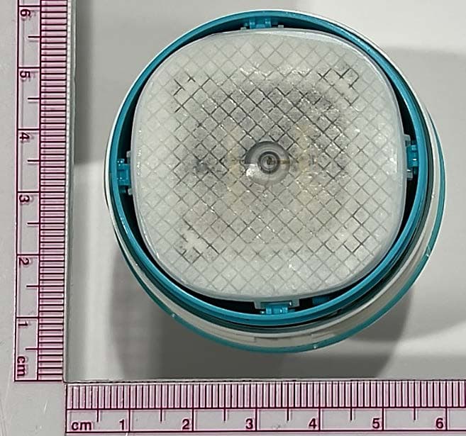
OH2BLEGST2
Jul 08, 2024Disposable glucose sensor transmitter
Equipment Class
DTS - Digital Transmission System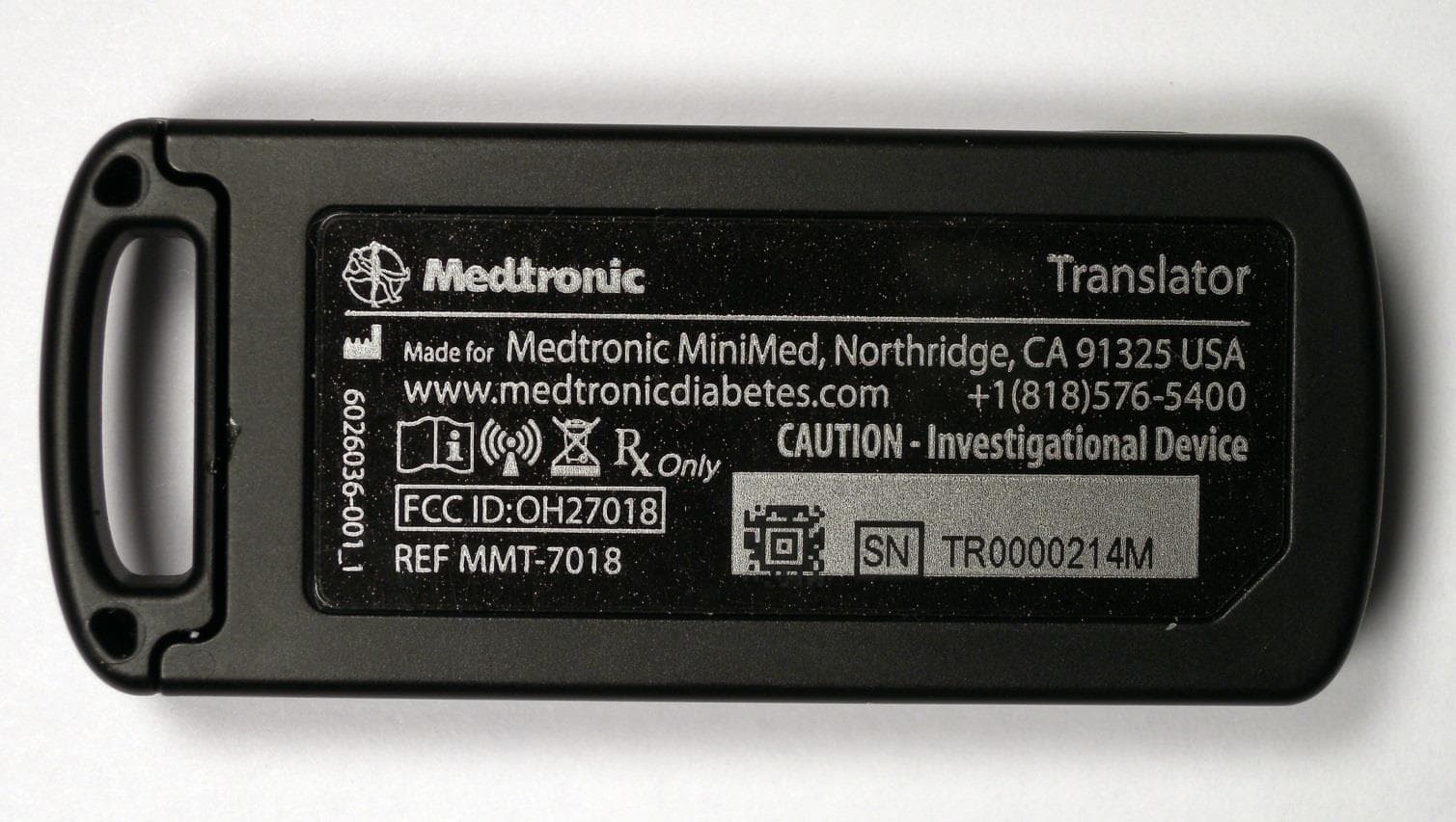
OH27018
Jul 09, 2015The Paradigm Translator allows RF intercommunication between Medtronic Minimed Paradigm series insulin pumps and commercially available smartphones running Medtronic application software.
Equipment Class
DXT - Part 15 Low Power Transceiver, Rx Verified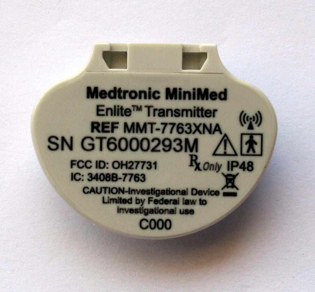
OH27731
Mar 10, 2015The Guardian Link transmitter is a component of the continuous glucose monitoring system for the MiniMed 600 series insulin pumps. The transmitter collects data from the glucose sensor and then wirelessly sends the data to the insulin pump.
Equipment Class
DTS - Digital Transmission System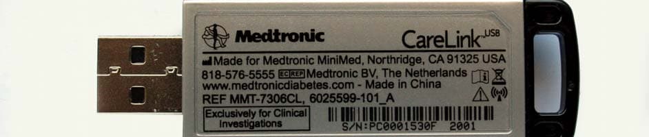
OH27306
Feb 08, 2015CareLINK USB
Equipment Class
DTS - Digital Transmission System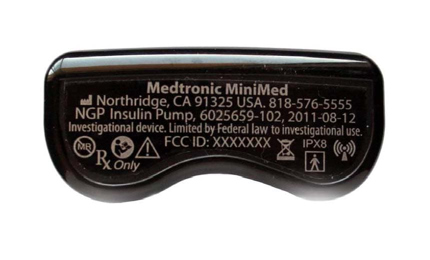
OH21510
Sep 24, 2014620G/630G/640G/670G Insulin Delivery Pump
Equipment Class
DTS - Digital Transmission System