OH2511Paradigm Infusion Pump, Model MMT-511
Medtronic MiniMed, Inc.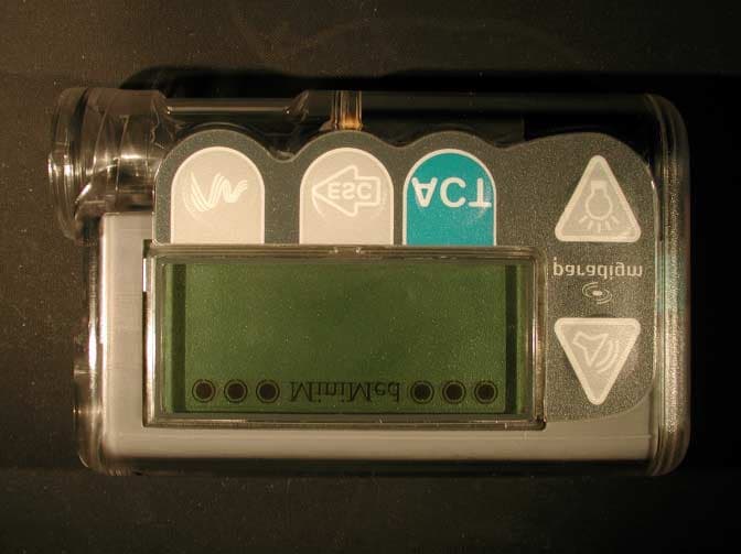
Click to zoom
Application Details
- Equipment Class
- DSR - Part 15 Remote Control/Security Device Transceiver
- Date of Grant
- May 16, 2001
- Application Purpose
- Original Equipment
- Date of Application
- May 14, 2001
- Equipment Note
- Paradigm Infusion Pump, Model MMT-511
- Frequency Range
- 916.00000000 - 916.00000000
- Company
- Medtronic MiniMed, Inc.
- Country
- United States
Documents & Files
Document Text
Text extracted from the exhibit documents filed with the FCC. Open a document above to read the original.
Attestation Statements
Page 1 ATTESTATION STATEMENT: MMT511 INSULIN PUMP SUMMARY: All tests per FCC Part 15, Paragraphs 15.205; 15.209; 15.231(b); and 15.231(c) were n - Performed The Equipment Under Test n - Fulfills the requirements of FCC Part 15, Paragraphs 15.205; 15.209; 15.231(b); and 15.231(c). - TÜV PRODUCT SERVICE, INC. - Responsible Engineer: Jim Owen (EMC Engineer) FIGURE 1 -SINGLE COMMAND Test Equipment: AGILENT 54622D Mixed Signal Oscilloscope MID # 11134 CAL: 11/20/00, NEXT CAL: 5/19/01 Test Date: 5/3/01 Description: Figure 1 illustrates a single command from the perspective of a Paradigm Pump AF Board. AX (Pin 21 U3) receives the transmitted data from an AF Cradle. Following is a transmission from the AF board at TX (Pin 5 U3). The final reception is the Acknowledge to end AF communications. Six seconds is shown to illustrate that there is at least five seconds whereby no AF occurs after AF communication ends. Tester: .Q*~g? A~' Engineer III, Electronic Minimed Inc. Witness: ~\ .s.. lO .6 \ Name Date ~~-ovr V l ~ ~ ~ ~G~...~- """""\~,~ \\I~ .
External Photos
CASE CASE CASE CASE CASE
ID Label/Location Info
gU A --. NOTE-THE FOLLOWING FOR MINIMED -RECEIVING INSPECTION USE. FOR SUPPLIER REFERENCE -ONLY. - 1 .O REFERENCE DOCUMENTS: 1.1 DIM1002 1.1 DIM1013 1.2 DIM1500 2.0 INSPECTION NOTES: 2.1 FOUIPMENT &xl \A3. T3. El b--------- 2.46O+i.O10 2.2 SAMPLING <xx) s4- 1 .O 2.3 INSPECT ARTWORK AND COLOR PER NOTES 9 > 2.4 VISUAL INSPECTION PER NOTE A 3.0 CERTIFICATION REQUIREMENTS: 3.1 CERTIFICATION OF MATERIALS REQUIRED. 6 P - Northridge, Co, USA 300-646-4633. 818-362-5958 Ifwww.minimed.com _............. _-.-~ I I * - \4X R.073 2099 * 818-576-555 (24- hour Help Line) LAYER 4 L4YER 1 LAYER 3 LAYER 2 - 4X R.073 -312 ,-313A LAYERING FOR BOTH LABELS EC0 NO. DATE REV COUNTRY SECONDARY PRIMARY PRIMARY COPY COLOR ICON COLOR BORDER COLOR ARTWORK PN SECONDARY BACKGROUND COLOR A PRIMARY COPY COLOR PRIMARY BACKGROUND COLOR A NELSON NAME PLATE s-221 (PMS 432C) NELSON NAME PLATE S-6A (PMS 429) NELS6N NAME PLATE S-221 (PMS 432C) NELSON NAME PLATE S-6A (PMS 429) NELSON NAME NELSON NAME PLATE S-6A PLATE S-221 (PMS 429) (PMS 432C) NELSON NAME PLATE S-6A (PMS 429) NELSON NAME PLATE S-221 (PMS 432C) NELkQN NAME PLATE s-221 (PMS 432C) NELSON NAME PLATE S-6A (PMS 429) ARTWORK REV )ART NUMBER PART REV D6024600-312 D6024600-313 -. D6024600-314 D6024609~3 15 D6024600-3El A L USA/ CANADA EH868 WHITE NELSON NAME PLATE S-221 (PMS 432C) UW CANADA WHITE Eli868 NELSON NAME PLATE S-221 (PMS 432C) WHITE A 12 AREA TO INCLUDE ADHESIVE.- A 11 BACKGROUND COLOR TO BE WHITE. El243 NELSON NAME PLATE S-221 (PMS 432C) USA/ CANADA NELSON NAME PLATE S-221 (PMS 432C) WHITE DMP6024600-314 NELSON NAME PLATE s-221 (PMS 432C) WHITE DMP6024600-315 WHITE WHITE DMP6024600-3El A 10 BORDER COLOR TO BE WHITE. A 9 COPY COLOR: PMS432 3/01 USA/ CANADA EI: gyz NELSON NAME PLATE S-221 (PMS 4326) WHITE A 8 COPY COLOR TO BE WHITE. BACKGROUND COLOR: PMS429 LA 6 BACKGROUND COLOR: PMS432. 6/00 WHITE EUROPEAN UNION EH868 NELSON NAME PLATE S-221 (PMS 432C) A 5 AREA TO BE TRANSPARENT WITH NO TEXTURE. 4. TOTAL THICKNESS (LAYER ‘l-3) NOT TO EXCEED .OlO. @?i%@i+ 3. MATERIAL: LAYER 1. AUTOTEX 2V6, .006 THK. POLYESTER. 2. INK 3. 3M 467 ADHESIVE (.002 THK) 4. PAPER BACKINk. /\ 2 VENDOR: USE PART NUMBER AND PART REVISION SHOWN IN TABLE 1 TO CERTIFY PARTS. REVISION SHOWN IN TITLE BLTCK IS FOR MINIMED USE ONLY. A 1 DRAWING SHOWN FOR EXAMPLE ONLY. FOR SPECIFIC ARTWORK, SEE DMP PART NO. IN TABLE 1. NOTES: UNLESS OTHERWISE SPECIFIED
Internal Photos
INTERFACE BACK INTERFACE FRONT LCD BACK LCD FRONT MOTHER BOARD BACK MOTHER FRONT MOTHER OBLIQUE RF ANTENNA RF BACK 1 RF BACK 2 RF FRONT BOARDS STACKED SIDE BOARDS STACKED SIDE 1 BOARDS STACKED 3
RF Exposure Info
RF EXPOSURE STATEMENT: The EUT is categorically excluded from routine evaluation because it is a low power device.
Test Report
Report No. 101793 (pump)-08 (FCC ID: OH2511) Page 1 TÜV PRODUCT SERVICE 10040 Mesa Rim Road San Diego, CA 92121-2912 Phone 858 546 3999 FAX 858 546 0364 MEASUREMENT AND TECHNICAL REPORT MINIMED TECHNOLOGIES 18000 Devonshire Street Northridge, CA 91325 DATE: 15 May 2001 This Report Concerns:Original Grant: XClass II Change: Equipment Type:MMT511 Infusion Pump Deferred grant requested per 47 CFR 0.457(d)(1)(ii)?Yes: Defer until: No: X Company Name agrees to notify the Commission by:N/A of the intended date of announcement of the product so that the grant can be issued on that date. Transition Rules Request per 15.37?Yes:*No: X (*) FCC Part 15, Paragraphs 15.205; 15.209; 15.231(b); and 15.231(c) Report Prepared by: TÜV PRODUCT SERVICE 10040 Mesa Rim Road San Diego, CA 92121-2912 Phone: 858 546 3999 Fax: 858 546 0364 Report No. 101793 (pump)-08 (FCC ID: OH2511) Page 2 TÜV PRODUCT SERVICE 10040 Mesa Rim Road San Diego, CA 92121-2912 Phone 858 546 3999 FAX 858 546 0364 TABLE OF CONTENTS Pages 1 GENERAL INFORMATION3 1.1Product Description3 1.2Related Submittal Grant4 1.3Tested System Details4 1.4Test Methodology4 1.5Test Facility4 2 SYSTEM TEST CONFIGURATION5 2.1Justification5 2.2EUT Exercise Software5 2.3Special Accessories5 2.4Equipment Modifications5 2.5Configuration of Tested System5 3CONDUCTED EMISSION EQUIPMENT/DATA6 4RADIATED EMISSION EQUIPMENT/DATA7 Field Strength Calculation13 5Attestation Statement14 Report No. 101793 (pump)-08 (FCC ID: OH2511) Page 3 TÜV PRODUCT SERVICE 10040 Mesa Rim Road San Diego, CA 92121-2912 Phone 858 546 3999 FAX 858 546 0364 1 GENERAL INFORMATION 1.1Product Description EUT Description:Battery Powered Portable Drug Infusion Pump EUT Name:Paradigm Model No.:MMT-511 Serial No.:N/A Power Requirements Voltage:1.5VDC (AAA Battery) Typical Installation and/or Operating Environment Worn on belt or pocket by user EUT Operating Modes to be Tested -- 1.25U/Hr Basal Rate EUT System Components -- DescriptionModel #Serial #FCC ID # N/A Support Equipment -- DescriptionModel #Serial #FCC ID # Keyfob Remote MMT-503N/AOH2503 Oscillator Frequencies FrequencyDerived FrequencyComponent # / LocationDescription of Use 2MHz ìProcessor 32.763kHzASIC 44HzASIC Power Supply ManufacturerModel #Serial #Type N/A Power Line Filters ManufacturerModel #Location in EUT N/A Critical EMI Components (Capacitors, ferrites, etc.) DescriptionManufacturerPart # or ValueQtyComponent # / Location N/A EMC Critical Detail -- Describe other EMC Design details used to reduce high frequency noise. N/A Report No. 101793 (pump)-08 (FCC ID: OH2511) Page 4 TÜV PRODUCT SERVICE 10040 Mesa Rim Road San Diego, CA 92121-2912 Phone 858 546 3999 FAX 858 546 0364 1 GENERAL INFORMATION (continued) 1.2Related Submittal/Grant None 1.3Tested System Details The FCC IDs for all equipment, plus descriptions of all cables used in the tested system are: None 1.4Test Methodology Purpose of Test:To demonstrate compliance with the ANSI C63.4 setup. Test Performed:1. Conducted Emissions, FCC Part 2, Paragraphs 2.989, 2.991 and Part 22, Paragraph 22,816 2. Radiated Emissions EN55022: 1992 Class B limit, 30 - 1,000 MHz, 10 meters X3. Radiated Emission per FCC Part 15, Paragraph 15.109(a), 15.205, 15.209, & 15.231(b); 15.231(c) 4. Frequency Stability, Part 2, Paragraph 2.995, and Part 87, Paragraph 87.133 RF Output Power, Part 2, Paragraph 2.985, Part 22, Paragraph 22.917 Both Conducted and radiated testing were performed according to the procedures in FCC/ANSI C63.4 and CSA 108.8 - M1983. Radiated testing was performed at an antenna-to-EUT distance of 3 meters (1 - 25 GHz). 1.5Test Facility The open area test site and conducted measurement data were tested by: TÜV PRODUCT SERVICE 10040 Mesa Rim Road San Diego, CA 92121-2912 Phone: 619 546 3999 Fax: 619 546 0364 The Test Site Data and performance comply with ANSI 63.4 and are registered with the FCC, 7435 Oakland Mills Rd, Columbia Maryland 21046. All Measurement Data is acquired according to the content of FCC Measurement Procedure and ANSI C63.4, unless supplemented with additional requirements as noted in the test report. Report No. 101793 (pump)-08 (FCC ID: OH2511) Page 5 TÜV PRODUCT SERVICE 10040 Mesa Rim Road San Diego, CA 92121-2912 Phone 858 546 3999 FAX 858 546 0364 2.SYSTEM TEST CONFIGURATION 2.1Justification The EUT was initially tested for FCC emission in the following configuration: See Block Diagram. 2.2EUT Exercise Software None 2.3Special Accessories None 2.4Modification None 2.5Configuration of Tested System See Block Diagram. Report No. 101793 (pump)-08 (FCC ID: OH2511) Page 6 TÜV PRODUCT SERVICE 10040 Mesa Rim Road San Diego, CA 92121-2912 Phone 858 546 3999 FAX 858 546 0364 3CONDUCTED EMISSION EQUIPMENT/DATA The following data lists the significant emission frequencies, measured levels, correction factor (which includes cable and antenna corrections), the corrected reading, and the limit. VDC unit. Report No. 101793 (pump)-08 (FCC ID: OH2511) Page 7 TÜV PRODUCT SERVICE 10040 Mesa Rim Road San Diego, CA 92121-2912 Phone 858 546 3999 FAX 858 546 0364 4RADIATED EMISSION EQUIPMENT/DATA The following data lists the significant emission frequencies, measured levels, correction factor (which includes cable and antenna corrections), the corrected reading, and the limit. See following page(s). Report No. 101793 (pump)-08 (FCC ID: OH2511) Page 13 TÜV PRODUCT SERVICE 10040 Mesa Rim Road San Diego, CA 92121-2912 Phone 858 546 3999 FAX 858 546 0364 Emissions Test Conditions: FCC Part 15, Paragraph 15.109(a); 15.205; 15.209; and 15.231(b); 15.231(c) The measurements were performed at the following test location : o - Test not applicable Canyon #3, Carroll Canyon, San Diego SR-3, Shielded Room, 12’ x 20’ x 8’, Metal Chamber Radiated Emissions Testing was performed at a test distance of: 3 meters Test Equipment Used : Model No.Prop. No.DescriptionManufacturerSerial No.Cal Date 3115251/453Antenna, Double Ridge Guide EMCO9412-436310/01 3146244Antenna, Log Periodic Dipole EMCO1063020…
Text truncated - open the document above for the full version.
Contact Information
Applicant
Jonathan Tabalujan(Sr. Electrical Engineer)
Test Firm
TUV AmericaJames Owen
Technical Specifications
| # | Rule Parts | Frequency Range | Power Output |
|---|---|---|---|
| 1 | 15C | 916 MHz - 916 MHz | 750.00 µW |
Other Applications from Medtronic MiniMed, Inc.
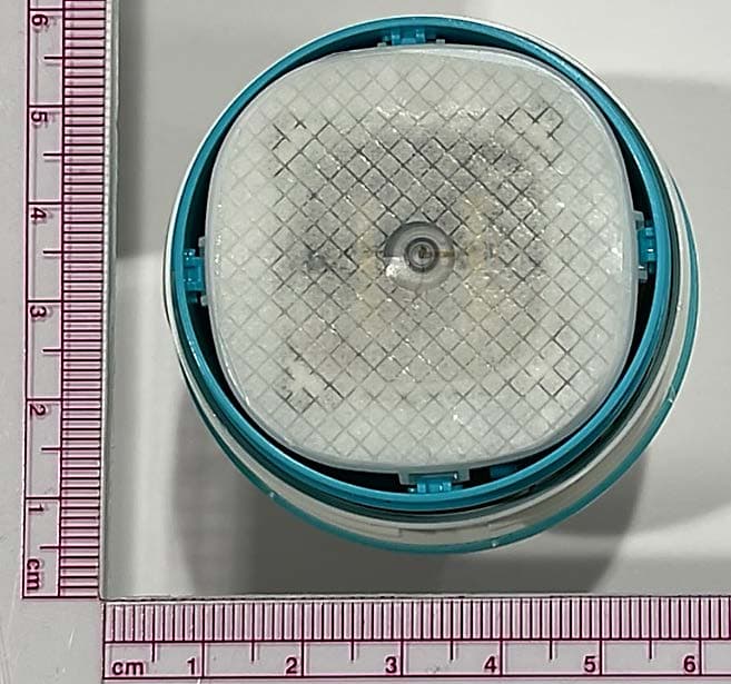
OH2BLEGST2
Jul 08, 2024Disposable glucose sensor transmitter
Equipment Class
DTS - Digital Transmission System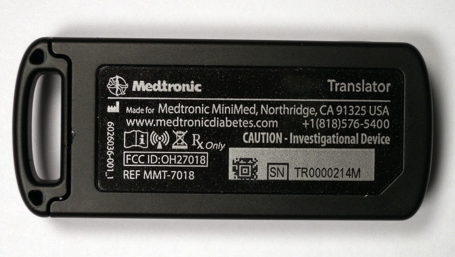
OH27018
Jul 09, 2015The Paradigm Translator allows RF intercommunication between Medtronic Minimed Paradigm series insulin pumps and commercially available smartphones running Medtronic application software.
Equipment Class
DXT - Part 15 Low Power Transceiver, Rx Verified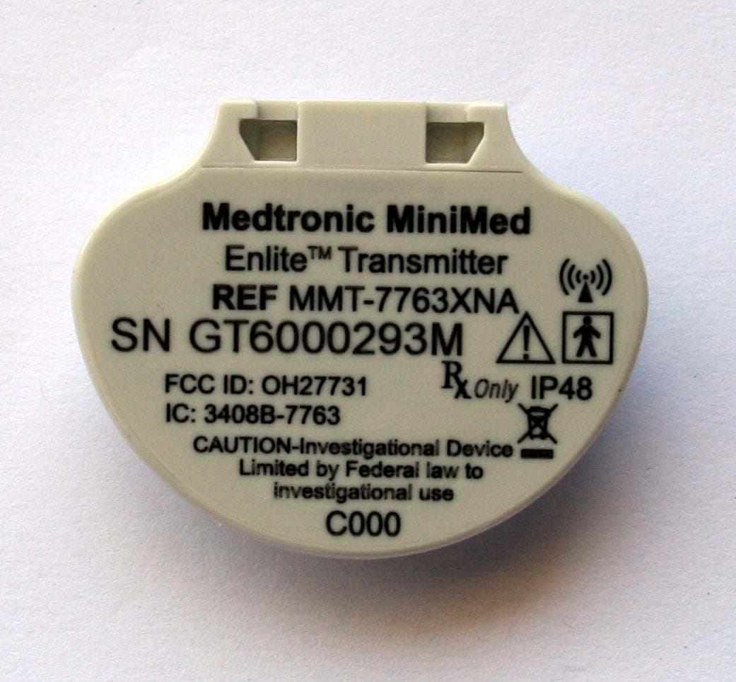
OH27731
Mar 10, 2015The Guardian Link transmitter is a component of the continuous glucose monitoring system for the MiniMed 600 series insulin pumps. The transmitter collects data from the glucose sensor and then wirelessly sends the data to the insulin pump.
Equipment Class
DTS - Digital Transmission System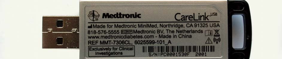
OH27306
Feb 08, 2015CareLINK USB
Equipment Class
DTS - Digital Transmission System
OH21510
Sep 24, 2014620G/630G/640G/670G Insulin Delivery Pump
Equipment Class
DTS - Digital Transmission System