OH27700NBlook Glucose Transmitter
Medtronic MiniMed, Inc.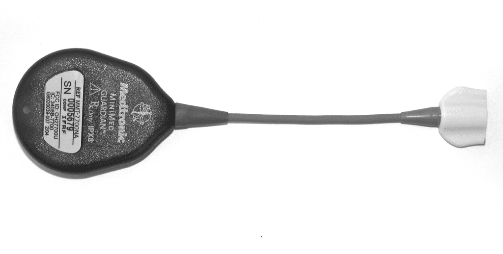
Click to zoom
Application Details
- Equipment Class
- DXX - Part 15 Low Power Communication Device Transmitter
- Date of Grant
- Feb 16, 2006
- Application Purpose
- Original Equipment
- Date of Application
- Feb 16, 2006
- Equipment Note
- Blook Glucose Transmitter
- Frequency Range
- 418.00000000 - 418.00000000
- Company
- Medtronic MiniMed, Inc.
- Country
- United States
Documents & Files
Document Text
Text extracted from the exhibit documents filed with the FCC. Open a document above to read the original.
Users Manual
Guardian ® RT Continuous Glucose Monitoring System REF MMT-7900 User Guide © 2005, Medtronic MiniMed. All rights reserved. Guardian ® , MiniMed ® and Sen-serter ® are registered trademarks of Medtronic MiniMed. Com-Station™, Shower-Pak™, Solutions™ Software are trademarks of Medtronic MiniMed. BD Logic™ is a trademark of Becton, Dickinson and Company Detachol ® is a registered trademark of Ferndale Laboratories, Inc. Polyskin ® is a registered trademark of the Kendall Healthcare Products Company. CaviCide ® is a registered trademark of the Metrex Research Corporation. IV3000 ® is a registered trademark of Smith & Nephew, Inc. YSI 2300 STAT Plus™ is a trademark of YSI Incorporated. The Guardian RT System is covered by the following Patent Nos: 5,390,671; 5,391,250; 5,568,806; 5,586,533; 5,586,553; 5,777,060; 5,779,665; 5,786,439; 5,851,197; 5,882,494; 5,954,643; 6,093,172; 6,248,067; 6,293,925; 6,368,141; 6,418,332; 6,424,847; 6,462,162; 6,520,326; 6,607,509; DES 433,755. The Guardian RT System is covered by other/pending patents. 6024979-012 072505 0459/0976 Table of Contentsi Table of Contents Chapter 1: Introduction ......................... 1 System Function....................................................... 2 System Components .................................................. 2 Glucose Sensor.................................................................... 2 Transmitter....................................................................... 2 Monitor............................................................................. 3 Monitor Buttons.................................................................. 3 Monitor Button Functions....................................................... 4 Monitor User Guide Terms...................................................... 4 Test Plug.......................................................................... 5 Sen-serter........................................................................ 5 Availability............................................................. 5 Help..................................................................... 6 Record Keeping........................................................ 6 Warranty............................................................... 6 User Safety............................................................. 7 Indications for Use............................................................... 7 Contraindications................................................................ 7 Warnings........................................................................... 8 Precautions........................................................................ 9 Adverse Reactions.............................................................. 11 Symptoms of Hypoglycemia.................................................. 11 Symptoms of Hyperglycemia................................................. 12 Blood Glucose Meter........................................................... 12 iiTable of Contents Chapter 2: Getting Started .....................13 Quick-Reference Guide ............................................. 13 Start-Up Process ..................................................... 17 Installing the Batteries....................................................... 17 Turning On the Monitor........................................................ 19 Turning Off the Monitor....................................................... 19 Home Screen.................................................................... 19 The Main Screens.................................................... 20 Programming the Monitor..................................................... 21 Setting the Language......................................................... 22 Setting the Time Display Format........................................... 23 Setting the Time and Date ................................................... 24 Clearing the Glucose History ................................................ 26 Setting the Glucose Unit ..................................................... 29 Setting the Low Glucose Alert............................................... 30 Setting the High Glucose Alert .............................................. 33 Setting the Alert Type........................................................ 36 Entering the Transmitter ID ................................................. 37 Inserting the Sensor ................................................ 39 Sensor Storage and Handling ................................................ 44 Sen-serter Maintenance ...................................................... 44 Affixing the Transmitter............................................ 45 Searching for the Transmitter............................................... 46 Connecting the Sensor to the Transmitter ................................ 47 Sensor Initialization........................................................... 48 Sensor Calibration............................................................. 48 Calibration Pending ........................................................... 50 No Sync ......................................................................... 50 Replacing the Glucose Sensor ..................................... 51 Removing the Sensor.......................................................... 51 Table of Contentsiii Chapter 3: Routine Operation.................. 53 Glucose History...................................................... 53 Entering Meter BG for Calibration ................................ 55 BG Due................................................................ 56 Enter BG ......................................................................... 57 Calibration Pending ............................................................ 57 No Sync .......................................................................... 58 Replacing the Glucose Sensor ..................................…
Text truncated - open the document above for the full version.
External Photos
TGMS EXTERNAL BACK TGMS EXTERNAL FRONT
ID Label/Location Info
TGMS EXTERNAL FRONT
Internal Photos
PCB BOTTOM 1 PCB BOTTOM 2 PCB TOP 1 PCB TOP 2
Test Report
Report No. SC506393-08 Page 1 of 11 Rev.No 1.0 TÜV AMERICA INC 10040 Mesa Rim Road San Diego, CA 92121-2912 Phone 858 678 1400 FAX 858 546 0364 MEASUREMENT AND TECHNICAL REPORT MEDTRONIC MINIMED 18000 Devonshire Street Northridge, CA 91325 DATE: 06 January 2006 This Report Concerns: Original Grant: X Class II Change: Equipment Type: TGMS II Deferred grant requested per 47 CFR 0.457(d)(1)(ii)? Yes: Defer until: No: X Company Name agrees to notify the Commission by: N/A of the intended date of announcement of the product so that the grant can be issued on that date. Transition Rules Request per 15.37? Yes: No: X* (*) FCC Part 15, Paragraph(s) 15.231(a), 15.231(c), and 15.231(e) Report Prepared by: TÜV AMERICA, INC 10040 Mesa Rim Road San Diego, CA 92121-2912 Phone: 858 678 1400 Fax: 858 546 0364 Report No. SC506393-08 Page 2 of 11 Rev.No 1.0 TÜV AMERICA INC 10040 Mesa Rim Road San Diego, CA 92121-2912 Phone 858 678 1400 FAX 858 546 0364 TABLE OF CONTENTS Pages 1.0 GENERAL INFORMATION 3 - 4 1.1 Product Description 3 1.2 Related Submittal Grant 3 1.3 Tested System Details 3 1.4 Test Methodology 3 1.5 Test Facility 4 2.0 SYSTEM TEST CONFIGURATION 5 2.1 Justification 5 2.2 EUT Exercise Software 5 2.3 Special Accessories 5 2.4 Equipment Modifications 5 2.5 Configuration of Test System 5 3.0 DEACTIVATION EQUIPMENT/DATA EMISSION BANDWIDTH EQUIPMENT/DATA FIELD STRENGTH OF EMISSIONS EQUIPMENT/DATA 6 - 10 4.0 ATTESTATION STATEMENT 11 Report No. SC506393-08 Page 3 of 11 Rev.No 1.0 TÜV AMERICA INC 10040 Mesa Rim Road San Diego, CA 92121-2912 Phone 858 678 1400 FAX 858 546 0364 1.0 GENERAL INFORMATION 1.1 Product Description None 1.2 Related Submittal Grant None 1.3 Tested System Details The FCC ID’s for all equipment, plus descriptions of all cables used in the tested system are: None 1.4 Test Methodology Purpose of Test: To demonstrate compliance with the following tests. Test Summary Summary of Results Test Description Paragraph Number Low Channel Mid Channel High Channel Pass/Fail Deactivation 15.231(a) -- 50 mS -- Pass Emissions Bandwidth 15.231(c) -- 60.2 kHz -- Pass Field Strength of Emissions 15.231(e) -- 68.8 dBμV/m @ 418 MHz -- Pass Testing was performed according to the procedures in FCC/ANSI C63.4 and CSA 108.8-M1983. Report No. SC506393-08 Page 4 of 11 Rev.No 1.0 TÜV AMERICA INC 10040 Mesa Rim Road San Diego, CA 92121-2912 Phone 858 678 1400 FAX 858 546 0364 1.5 Test Facility The open area test site and conducted measurement data were tested by: TÜV AMERICA, INC 10040 Mesa Rim Road San Diego, CA 92121-2912 Phone: 858 678 1400 Fax: 858 546 0364 The Test Site Data and performance comply with ANSI C63.4 and are registered with the FCC, 7435 Oakland Mills Road, Columbia Maryland 21046. All Measurement Data is acquired according to the content of FCC Measurement Procedure and ANSI C63.4, unless supplemented with additional requirements as noted in the test report. Report No. SC506393-08 Page 5 of 11 Rev.No 1.0 TÜV AMERICA INC 10040 Mesa Rim Road San Diego, CA 92121-2912 Phone 858 678 1400 FAX 858 546 0364 2.0 SYSTEM TEST CONFIGURATION 2.1 Justification The EUT was initially tested for FCC emissions in the following configuration: See Test Setup Photos Exhibit 2.2 EUT Exercise Software None 2.3 Special Accessories None 2.4 Equipment Modifications None 2.5 Configuration of Test System See Test Setup Photos Exhibit Report No. SC506393-08 Page 6 of 11 Rev.No 1.0 TÜV AMERICA INC 10040 Mesa Rim Road San Diego, CA 92121-2912 Phone 858 678 1400 FAX 858 546 0364 3.0 DEACTIVATION EQUIPMENT/DATA EMISSION BANDWIDTH EQUIPMENT/DATA FIELD STRENGTH OF EMISSIONS EQUIPMENT/DATA Test Conditions: DEACTIVATION: FCC Part 15.231(a) EMISSION BANDWIDTH: FCC Part 15.231(c) FIELD STRENGTH OF EMISSIONS: FCC Part 15.231(e) The following measurements were performed at the San Diego Testing Facility: - Test not applicable - Roof (Small Open Area Test Site) Test Equipment Used: Model No. Prop. No. Description Manufacturer Serial No./Version No. Date Cal’ed 3146 243 Log Periodic Dipole Antenna EMCO 106X 06/05 3146 418 Log Periodic Antenna EMCO 9402-3775 03/05 3115 453 Double Ridge Antenna EMCO 9412-4364 08/05 E4440A 6814 Spectrum Analyzer Hewlett Packard MY42510441 12/04 HFOATS -- Test Software TUV America Beta231 N/A Remarks: One year calibration cycle for all test equipment and sites. Report No. SC506393-08 Page 7 of 11 Rev.No 1.0 TÜV AMERICA INC 10040 Mesa Rim Road San Diego, CA 92121-2912 Phone 858 678 1400 FAX 858 546 0364 Report No. SC506393-08 5-second interval cycle. "No transmit activity occurs prior to triggered graph" for the deactivation graph. Page 8 of 11 Rev.No 1.0 TÜV AMERICA INC 10040 Mesa Rim Road San Diego, CA 92121-2912 Phone 858 678 1400 FAX 858 546 0364 Report No. SC506393-08 Page 9 of 11 Rev.No 1.0 TÜV AMERICA INC 10040 Mesa Rim Road San Diego, CA 92121-2912 Phone 858 678 1400 FAX 858 546 0364 Report No. SC506393-08 Page 10 of 11 Rev.No 1.0 TÜV AMERICA INC 10040 Mesa Rim Road San Diego, CA 92121-2912 Phone 858 678 1400 FAX 858 546 0364 Report No. SC506393-08 4.0 ATTESTATION STATEMENT GENERAL REMARKS: SUMMARY: All tests were performed per CFR 47, Part(s) 15.231(a), 15.231(c), and 15.231(e) - Performed The Equipment Under Test - Fulfills the requirements of CFR 47, Part(s) 15.231(a), 15.231(c), and 15.231(e) Testing Start Date: 12 December 2005 Testing End Date: 12 December 2005 - TÜV AMERICA, INC. - Reviewing Engineer: Test Engineer: David Gray Ralph Cole (EMC Engineer In Charge) (EMC Engineer) Page 11 of 11 Rev.No 1.0 TÜV AMERICA INC 10040 Mesa Rim Road San Diego, CA 92121-2912 Phone 858 678 1400 FAX 858 546 0364
Contact Information
Applicant
Jonathan Tabalujan(Sr. Electrical Engineer)
Test Firm
TUV America Inc.Jim Owen
Technical Specifications
| # | Rule Parts | Frequency Range | Power Output |
|---|---|---|---|
| 1 | 15C | 418 MHz - 418 MHz | - |
Other Applications from Medtronic MiniMed, Inc.
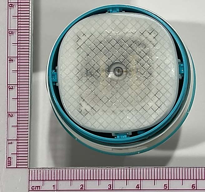
OH2BLEGST2
Jul 08, 2024Disposable glucose sensor transmitter
Equipment Class
DTS - Digital Transmission System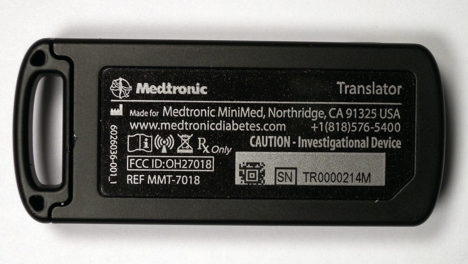
OH27018
Jul 09, 2015The Paradigm Translator allows RF intercommunication between Medtronic Minimed Paradigm series insulin pumps and commercially available smartphones running Medtronic application software.
Equipment Class
DXT - Part 15 Low Power Transceiver, Rx Verified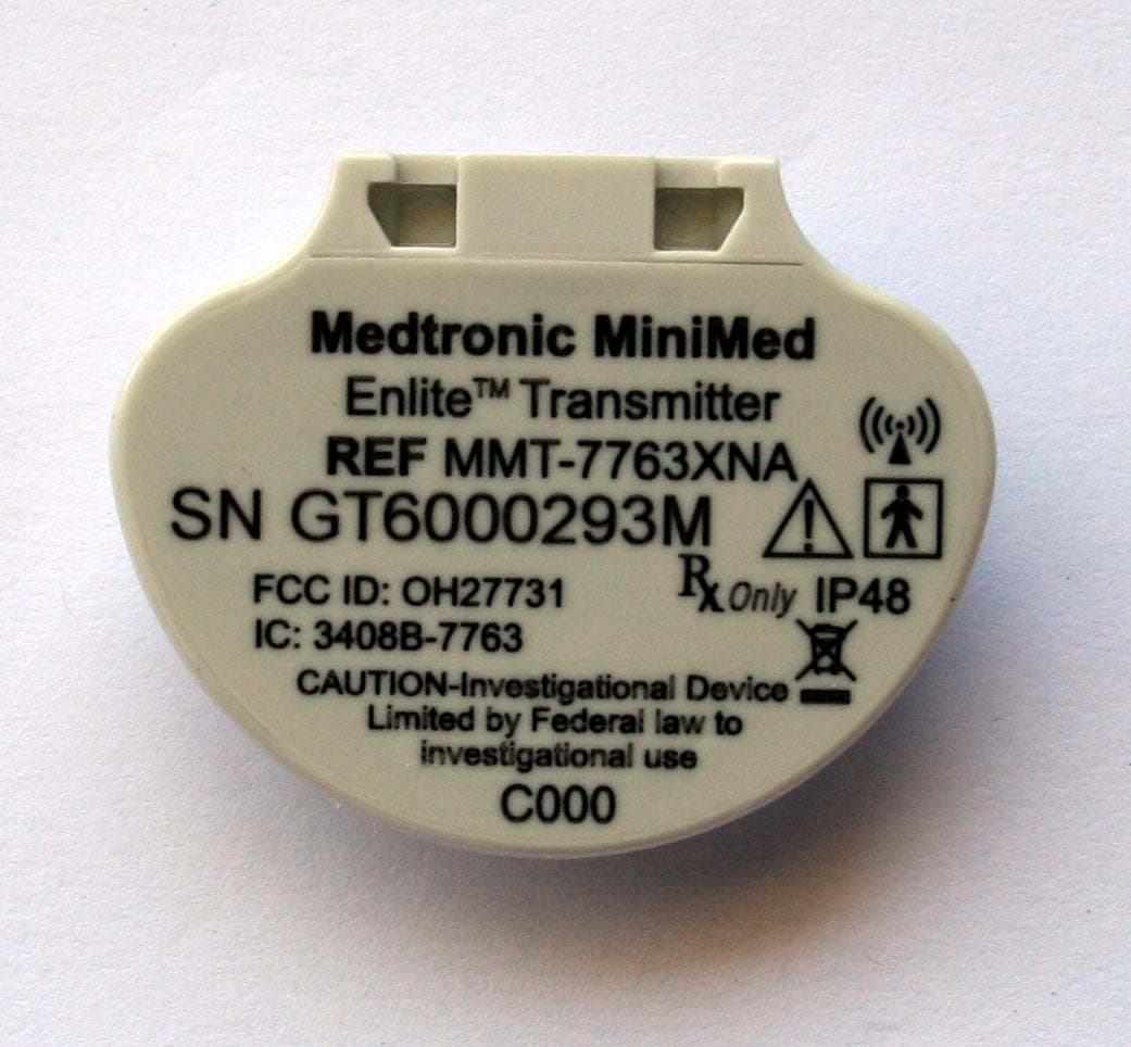
OH27731
Mar 10, 2015The Guardian Link transmitter is a component of the continuous glucose monitoring system for the MiniMed 600 series insulin pumps. The transmitter collects data from the glucose sensor and then wirelessly sends the data to the insulin pump.
Equipment Class
DTS - Digital Transmission System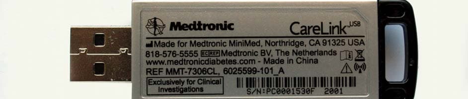
OH27306
Feb 08, 2015CareLINK USB
Equipment Class
DTS - Digital Transmission System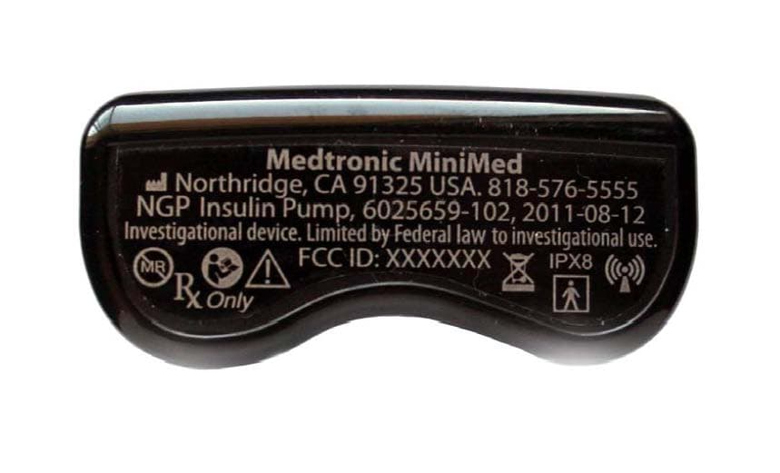
OH21510
Sep 24, 2014620G/630G/640G/670G Insulin Delivery Pump
Equipment Class
DTS - Digital Transmission System