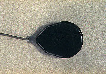
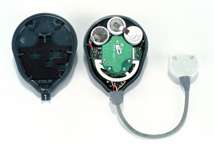
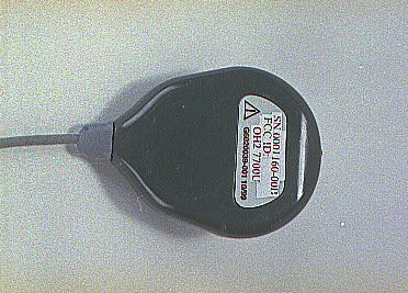
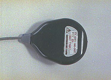
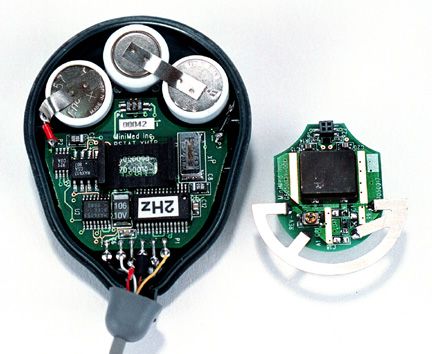
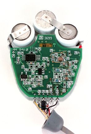
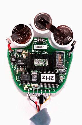
OH27700UTGMS Potentiostat Transmitter Device, MMT-7700
Medtronic MiniMed, Inc.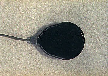
Click to zoom
Application Details
- Equipment Class
- DXX - Part 15 Low Power Communication Device Transmitter
- Date of Grant
- Jul 27, 2000
- Application Purpose
- Original Equipment
- Date of Application
- Jul 27, 2000
- Equipment Note
- TGMS Potentiostat Transmitter Device, MMT-7700
- Frequency Range
- 418.00000000 - 418.00000000
- Company
- Medtronic MiniMed, Inc.
- Country
- United States
Documents & Files
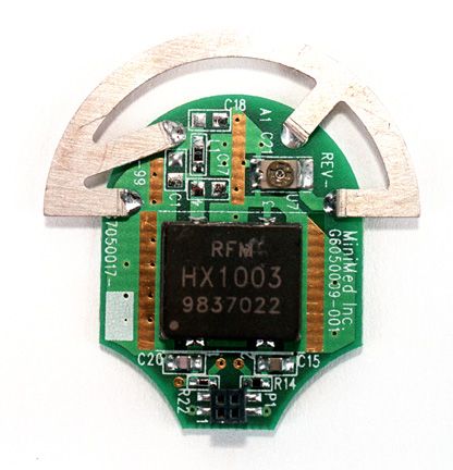
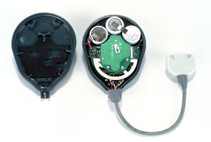
Document Text
Text extracted from the exhibit documents filed with the FCC. Open a document above to read the original.
Attestation Statements
Report No. 0273-08 (FCC ID: OH2 7700U) Page 1 of 13 Rev.No 1.0 ATTESTATION STATEMENT: All tests according to Part 15, Paragraph 15.231(c) and (e) were n - Performed The Equipment Under Test n - Fulfills the general approval requirements of Part 15, Paragraph 15.231(c)(e). _______________________ - TÜV PRODUCT SERVICE, INC. - Responsible Engineer: Mary Washington (EMC Engineer)
Test Report
Report No. 0273-08 (FCC ID: OH2 7700U) Page 1 of 15 Rev.No 1.0 MEASUREMENT AND TECHNICAL REPORT MINIMED, INC. 12744 San Fernando Road Sylmar, CA 91342 DATE: 26 July 2000 This Report Concerns:Original Grant: XClass II Change: Equipment Type:TGMS Potentiostat Transmitter Device, Model MMT-7700 Deferred grant requested per 47 CFR 0.457(d)(1)(ii)?Yes: Defer until: No: X Company Name agrees to notify the Commission by:N/A of the intended date of announcement of the product so that the grant can be issued on that date. Transition Rules Request per 15.37?Yes:*No: (*) FCC Part 15, Paragraph 15.231(c)(e) Report Prepared by: TÜV PRODUCT SERVICE 10040 Mesa Rim Road San Diego, CA 92121-2912 Phone: 619 546 3999 Fax: 619 546 0364 Report No. 0273-08 (FCC ID: OH2 7700U) Page 2 of 15 Rev.No 1.0 TABLE OF CONTENTS Pages 1 GENERAL INFORMATION3 1.1Product Description3 1.2Related Submittal Grant4 1.3Tested System Details4 1.4Test Methodology4 1.5Test Facility4 2 SYSTEM TEST CONFIGURATION5 2.1Justification5 2.2EUT Exercise Software5 2.3Special Accessories5 2.4Equipment Modifications5 2.5Configuration of Tested System5 3 CONDUCTED EMISSION EQUIPMENT LIST/DATA 6 4RADIATED EMISSION EQUIPMENT LIST/DATA7 4.1Field Strength Calculation13 5Duty Cycle14 6Signature Page15 Report No. 0273-08 (FCC ID: OH2 7700U) Page 3 of 15 Rev.No 1.0 1 GENERAL INFORMATION 1.1Product Description TGMS Potentiostat Transmitter Device, Model MMT-7700 DESCRIPTION OF EUT:Glucose Transmitter Components of EUT DescriptionModel NumberSerial NumberFCC ID Number Glucose TransmitterMMT-7700--OH27700U OPERATING MODE(S):On-off keyed 418 MHz I/O CABLES CONNECTIONGlucose sensor cable/connector SHIELDYes CONNECTORSCustom glucose sensor connector TERMINATION TYPECrimp and solder LENGTH3 and ½ inches REMOVABLENo POWER CORDSN/A POWER INTERFACE FREQUENCY/AC/DC VOLTAGE:N/A OSCILLATOR FREQUENCIES FREQUENCYEUT LOCATIONDESCRIPTION OF USE 418 MHz, 940 kHz, 32768 Hz RF Xmtr PCBA, PSAT PCBA, PSTAT Transmitter carrier, microcontroller clk., RTC POWER SUPPLYN/A POWER LINE FILTERSN/A CRITICAL EMI COMPONENTSN/A INTERFACING AND/OR SIMULATORS PERIPHERAL EQUIPMENT: DESCRIPTIONMANUFACTURERMODEL #SERIAL #FCC ID Glucose sensor assemblyMiniMedMMT-7002---- Report No. 0273-08 (FCC ID: OH2 7700U) Page 4 of 15 Rev.No 1.0 1 GENERAL INFORMATION (continued) 1.2Related Submittal/Grant None 1.3Tested System Details The FCC IDs for all equipment, plus descriptions of all cables used in the tested system are: None 1.4Test Methodology Purpose of Test:To demonstrate compliance with the ANSI C63.4 setup. Test Performed:*1. Conducted Emissions 2. Radiated Emissions, EN55022: 1992 Class B limit, 30 - 1,000 MHz, 10 meters X3. Radiated Emission per FCC Part 15, Paragraph 15.231(c)(e) 4. Engineering evaluations X5. 20 dB Bandwidth (*) EUT battery operated. 1.5Test Facility The open area test site and conducted measurement data were tested by: TÜV PRODUCT SERVICE 10040 Mesa Rim Road San Diego, CA 92121-2912 Phone: 619 546 3999 Fax: 619 546 0364 The Test Site Data and performance comply with ANSI 63.4 and are registered with the FCC, 7435 Oakland Mills Rd, Columbia Maryland 21046. All Measurement Data is acquired according to the content of FCC Measurement Procedure and ANSI C63.4, unless supplemented with additional requirements as noted in the test report. Report No. 0273-08 (FCC ID: OH2 7700U) Page 5 of 15 Rev.No 1.0 2.SYSTEM TEST CONFIGURATION 2.1Justification The TGMS Potentiostat Transmitter Device, Model MMt-7700 was initially tested for FCC emission in the following configuration: See Block Diagram. 2.2EUT Exercise Software None 2.3Special Accessories None 2.4Modification None 2.5Configuration of Tested System See Block Diagram. Report No. 0273-08 (FCC ID: OH2 7700U) Page 6 of 15 Rev.No 1.0 3CONDUCTED EMISSION EQUIPMENT LIST/DATA Not performed - EUT battery operated. See following page(s). Report No. 0273-08 (FCC ID: OH2 7700U) Page 7 of 15 Rev.No 1.0 4RADIATED EMISSION EQUIPMENT LIST/DATA The following data lists the significant emission frequencies, measured levels, correction factor (which includes cable and antenna corrections), the corrected reading, and the limit. See following page(s). Report No. 0273-08 (FCC ID: OH2 7700U) Page 8 of 15 Rev.No 1.0 Emissions Test Conditions: RADIATED EMISSIONS (Electric Field) The RADIATED EMISSIONS measurements were performed at the following test location : o - Test not applicable n - Roof (Small Open Area Test Site) Testing was performed at a test distance of: n - 3 meters Test Equipment Used : Model No.ManufacturerDescriptionSerial No.Prop. No.Cal Due Date n -8566BHewlett PackardSpectrum Analyzer2115A0084272003/01 n -85662BHewlett PackardSpectrum Analyzer Display2112A0218572103/01 n -3115EMCOAntenna, Double Ridge Guide249525110/00 n -AFD3-0208-40-STMiteq, Inc.Pre-Amplifier (30 dB gain), 2 to 8 GHz 155382367* n -3146EMCOAntenna, LPA--24410/00 Remarks:(*) Verified internally. Report No. 0273-08 (FCC ID: OH2 7700U) Page 10 of 15 Rev.No 1.0 Emissions Test Conditions: 20 dB Bandwidth The 20 DB BANDWIDTH measurements were performed at the following test location : o - Test not applicable n - SR3 - Shielded Room, 12’ x 20’ x 8’, Metal Chamber Test Equipment Used : Model No.ManufacturerDescriptionSerial No.Prop. No.Cal Due Date n -8568BHewlett PackardSpectrum Analyzer3303A003654300501 n -CBL6111ChaseAntenna Bilog1013460* Remarks:(*) Verified internally. Report No. 0273-08 (FCC ID: OH2 7700U) Page 13 of 15 Rev.No 1.0 4.1Field Strength Calculation If a preamplifier was used during the Radiated Emission Testing, it is required that the amplifier gain must be subtracted from the Spectrum Analyzer (Meter) Reading. In addition, a correction factor for the antenna , cable used and a distance factor, if any, must be applied to the Meter Reading before a true field strength reading can be obtained. In the automatic measurement, these considerations are automatically presented as a part of the print out. In the case of manual measurements and for greater efficie…
Text truncated - open the document above for the full version.
Test Setup Photos
Radiated Emissions Test Setup Table EUT Turntable 3 meters Bulkhead Test Control Room Spectrum Analyzer RF Input
Contact Information
Applicant
Jonathan Tabalujan(Sr. Electrical Engineer)
Technical Contact
TUV Product ServiceJudy F Evans
[email protected]858 546 3999
10040 Mesa Rim Road · SAn Diego, California · United States
Test Firm
TUV AmericaJames Owen
Technical Specifications
| # | Rule Parts | Frequency Range | Power Output |
|---|---|---|---|
| 1 | 15C | 418 MHz - 418 MHz | - |
Other Applications from Medtronic MiniMed, Inc.
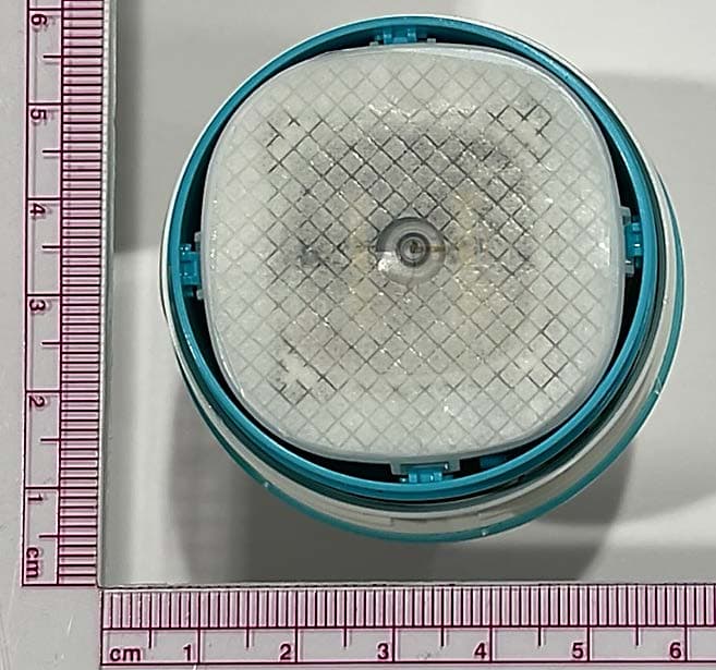
OH2BLEGST2
Jul 08, 2024Disposable glucose sensor transmitter
Equipment Class
DTS - Digital Transmission System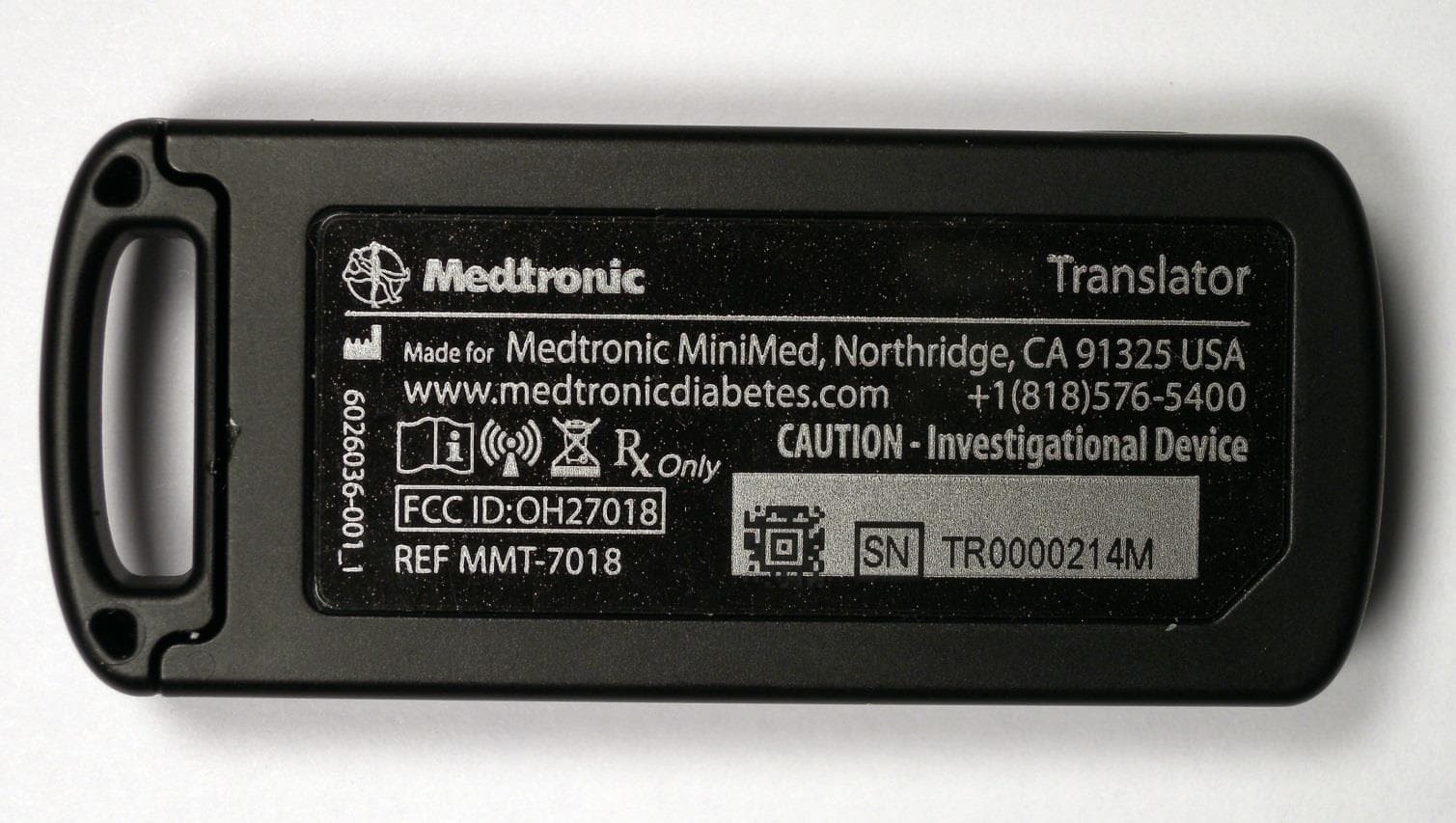
OH27018
Jul 09, 2015The Paradigm Translator allows RF intercommunication between Medtronic Minimed Paradigm series insulin pumps and commercially available smartphones running Medtronic application software.
Equipment Class
DXT - Part 15 Low Power Transceiver, Rx Verified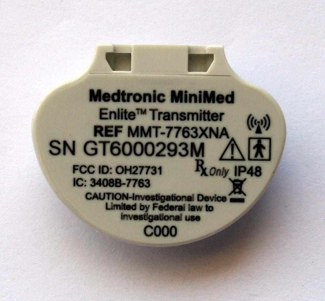
OH27731
Mar 10, 2015The Guardian Link transmitter is a component of the continuous glucose monitoring system for the MiniMed 600 series insulin pumps. The transmitter collects data from the glucose sensor and then wirelessly sends the data to the insulin pump.
Equipment Class
DTS - Digital Transmission System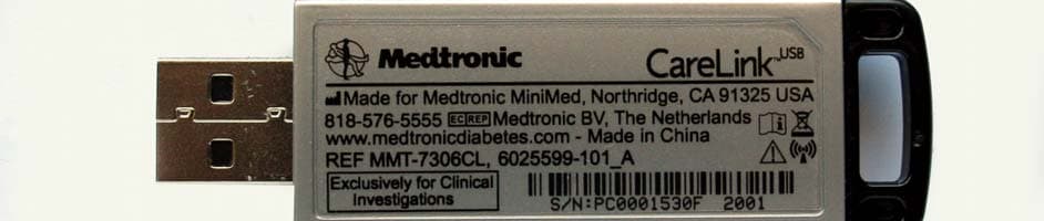
OH27306
Feb 08, 2015CareLINK USB
Equipment Class
DTS - Digital Transmission System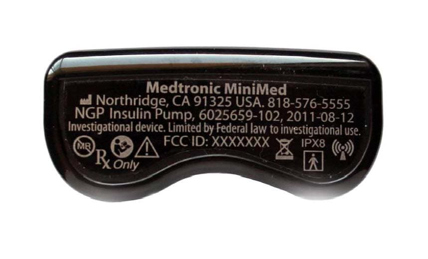
OH21510
Sep 24, 2014620G/630G/640G/670G Insulin Delivery Pump
Equipment Class
DTS - Digital Transmission System