OIWCBDAESMR1W60Bi-directional amplifier
Dekolink Wireless Ltd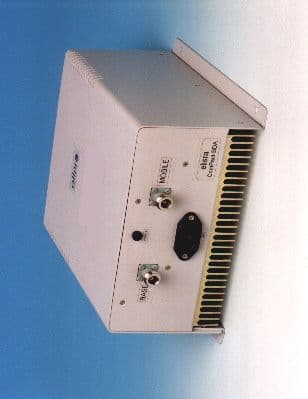
Click to zoom
Application Details
- Equipment Class
- AMP - Amplifier
- Date of Grant
- Jul 13, 1999
- Application Purpose
- Original Equipment
- Date of Application
- Apr 13, 1999
- Equipment Note
- Bi-directional amplifier
- Frequency Range
- 851.00000000 - 866.00000000
- Company
- Dekolink Wireless Ltd
- Country
- Israel
Documents & Files
Document Text
Text extracted from the exhibit documents filed with the FCC. Open a document above to read the original.
Attestation Statements
FCC ID: OIW CBDAESMR1W60 Exhibit 1 - Page 1 of 3 Application for FCC Certification and Technical Report. Form 731 Confirmation Number: EA93872 FCC ID: OIWCBDAESMR1W60 Date of Submission: 14 April, 1999 Applicant Name: Elisra Electronic Systems Ltd. Mailing Address: 48 Mivtza Kadesh St. Bene Beraq 51203, Israel Equipment Name: MW-CBDA-ESMR-1W60 Cellular Bi-Directional Amplifier/Booster FCC ID: OIW CBDAESMR1W60 Exhibit 1 - Page 2 of 3 CONTENTS EXHIBIT 1: STATEMENT OF CERTIFICATION ----- 47CFR 2.1033(a) EXHIBIT 2: IDENTIFICATION LABEL ----- 47CFR 2.983(f) EXHIBIT 3: EXTERNAL VIEW PHOTOGRAPHS EXHIBIT 4: INTERNAL VIEW PHOTOGRAPHS EXHIBIT 5: INSTALLATION AND OPERATING INSTRUCTIONS ----- 47CFR 2.1033(3). EXHIBIT 6: PARTS LIST EXHIBIT 7: ELECTRICAL SCHEMATICS EXHIBIT 8: DESCRIPTION OF THE CIRCUIT FUNCTIONS AND BLOCK DIAGRAM ----- 47CFR 2.1033(4). EXHIBIT 9: MEASURED DATA ON CONDUCTED AND RADIATED EMISSIONS ----- 47CFR 2.1033(6) EXHIBIT 10: MEASURED DATA ON OCCUPIED BANDWIDTH ----- 47 CFR 2.989, 90.210(b), 90.210(g) and 90.691(a). EXHIBIT 11: MEASURED DATA ON CONDUCTED SPURIOUS EMISSIONS ----- 47 CFR 2.991 EXHIBIT 12: MEASURED DATA ON RADIATED HARMONICS AND SPURIOUS EMISSIONS ----- 47 CFR 2.993 . FCC ID: OIW CBDAESMR1W60 Exhibit 1 - Page 3 of 3 EXHIBIT 1. STATEMENT OF CERTIFICATION -----47CFR 2.1033(a). The MW-CBDA-ESMR-1W60 Cellular Bi-Directional Amplifier/Booster is an equipment subject to FCC authorization by certification procedure pursuant 47CFR Sections 2.1031 through 2.1043. Electronically submitted FCC Form 731 was sent under Confirmation No. EA93872 on 04/14/1999.
Attestation Statements
FCC ID: OIW CBDAESMR1W60 Exhibit 1 - Page 1 of 3 Application for FCC Certification and Technical Report. Form 731 Confirmation Number: EA93872 FCC ID: OIWCBDAESMR1W60 Date of Submission: 14 April, 1999 Applicant Name: Elisra Electronic Systems Ltd. Mailing Address: 48 Mivtza Kadesh St. Bene Beraq 51203, Israel Equipment Name: MW-CBDA-ESMR-1W60 Cellular Bi-Directional Amplifier/Booster FCC ID: OIW CBDAESMR1W60 Exhibit 1 - Page 2 of 3 CONTENTS EXHIBIT 1: STATEMENT OF CERTIFICATION ----- 47CFR 2.1033(a) EXHIBIT 2: IDENTIFICATION LABEL ----- 47CFR 2.983(f) EXHIBIT 3: EXTERNAL VIEW PHOTOGRAPHS EXHIBIT 4: INTERNAL VIEW PHOTOGRAPHS EXHIBIT 5: INSTALLATION AND OPERATING INSTRUCTIONS ----- 47CFR 2.1033(3). EXHIBIT 6: PARTS LIST EXHIBIT 7: ELECTRICAL SCHEMATICS EXHIBIT 8: DESCRIPTION OF THE CIRCUIT FUNCTIONS AND BLOCK DIAGRAM ----- 47CFR 2.1033(4). EXHIBIT 9: MEASURED DATA ON CONDUCTED AND RADIATED EMISSIONS ----- 47CFR 2.1033(6) EXHIBIT 10: MEASURED DATA ON OCCUPIED BANDWIDTH ----- 47 CFR 2.989, 90.210(b), 90.210(g) and 90.691(a). EXHIBIT 11: MEASURED DATA ON CONDUCTED SPURIOUS EMISSIONS ----- 47 CFR 2.991 EXHIBIT 12: MEASURED DATA ON RADIATED HARMONICS AND SPURIOUS EMISSIONS ----- 47 CFR 2.993 . FCC ID: OIW CBDAESMR1W60 Exhibit 1 - Page 3 of 3 EXHIBIT 1. STATEMENT OF CERTIFICATION -----47CFR 2.1033(a). The MW-CBDA-ESMR-1W60 Cellular Bi-Directional Amplifier/Booster is an equipment subject to FCC authorization by certification procedure pursuant 47CFR Sections 2.1031 through 2.1043. Electronically submitted FCC Form 731 was sent under Confirmation No. EA93872 on 04/14/1999.
Cover Letter(s)
Hi Mr. Auster -- Please enter this information under the "cover letters" exhibit via "Add Attachments." Thank you, Bette Taube >>> "Shmuel Auster" <[email protected]> 04/15/99 02:50am >>> Dear Ms. Taube, Yesterday (04.14.99) I entered form 731 application (FCC ID: OIWCBDAESMR1W60 , Form 731 Confirmation Number: EA93872). Please correct this application by adding, in Item 10: "Equipment will be operated under FCC Rule Part(s): 90, 22. " (The numbers 90, 22 were deleted automatically during the process of writing this application, when I made an error and returned back to fix it). Thank you, Shmuel Auster - Chief Scientist Microwave Division Elisra Electronic Systems Ltd. Tel: +972 3 6175452 Fax: +972 3 6175299 E-mail: [email protected]
Cover Letter(s)
FCC ID: OIW CBDAESMR1W60 Page 1 of 1 EXHIBIT 13: Request for Confidentiality. We hereby request for application of confidentiality procedure while handling the following parts of our FCC certification application: One) EXHIBIT 6: Parts List; Two) EXHIBIT 7: Electrical Schematics.
Cover Letter(s)
FCC ID: OIW CBDAESMR1W60 Page 1 of 1 EXHIBIT 14: Operation of Elisra Bi-Directional Amplifier under 47CFR Part 22. We hereby confirm that Elisra Bi-Directional Amplifier Model MW-CBDA-ESMR-1W60 will be operated under Subpart F of Part 22, Rural Radiotelephone Service. This equipment shall not be operated under Cellular portion of FCC Rules Part 22.
ID Label/Location Info
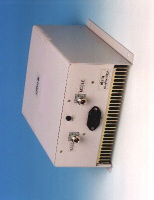
FCC ID: OIW CBDAESMR1W60 Exhibit 2 - Page 1 of 2 EXHIBIT 2: IDENTIFICATION LABEL ----- 47CFR 2.983(f). Pursuant 47CFR Section 2.983(f) see the Identification Label and Location Info. of the MW-CBDA-ESMR-1W60 Cellular Bi-Directional Amplifier/Booster. FCC ID: OIW CBDAESMR1W60 Exhibit 2 - Page 2 of 2 ComPact BDA
Operational Description
FCC ID: OIW CBDAESMR1W60 Exhibit 5 - Page 1 of 10 EXHIBIT 5: INSTALLATION AND OPERATING INSTRUCTIONS ----- 47CFR 2.1033(3). The following is a copy of Installation and Operating Instructions of the MW- CBDA-ESMR-1W60 Cellular Bi-Directional Amplifier/Booster. FCC ID: OIW CBDAESMR1W60 Exhibit 5 - Page 2 of 10 INSTALLATION AND OPERATING INSTRUCTIONS FOR MW-CBDA-ESMR-1W60 BI-DIRECTIONAL AMPLIFIER (COMPACT BDA) FCC ID: OIW CBDAESMR1W60 Exhibit 5 - Page 3 of 10 TABLE OF CONTENTS PARAGRAPHPAGE NO BDA OVERVIEW4 BDA BLOCK DIAGRAM DESCRIPTION4 BDA BLOCK DIAGRAM DRAWING5 ELECTRICAL SPECIFICATIONS6 MECHANICAL SPECIFICATIONS7 ENVIRONMENTAL CONDITIONS7 BDA CONNECTIONS8 PERIODIC MAINTENANCE8 DIAGNOSTIC GUIDE9 MECHANICAL OUTLINE10 FCC ID: OIW CBDAESMR1W60 Exhibit 5 - Page 4 of 10 BDA OVERVIEW: The BDA assembly provides an exceptional repeater/booster performances to extend the coverage area of radio communications in buildings and RF shielded environments. Features such as high linearity power amplifiers are contributing for the overall improved system linearity performances. The unit is based on a duplexed path configuration, having sharp out of band attenuation for improved isolation between the receiving and transmitting paths. BDA BLOCK DIAGRAM DESCRIPTION: The BDA Downlink path receives the RF signals from base station amplifies and transmits them to the subscriber. The BDA Uplink path receives the RF signals from the subscriber amplifies and transmits them to the base station. Two duplexers frequency separate the signals to the proper amplifying path and isolate the two signals. BDA with AGC (Option A) The amplifiers in this BDA have an AGC feedback loop. The AGC circuit senses the output power and when it exceeds the preset level of +20 dBm it introduces more attenuation. In this manner the gain of the amplifier is reduced, its output power is limited to +20 dBm and the Intermodulation products are kept low. The AGC Dynamic range is 30 dB. FCC ID: OIW CBDAESMR1W60 Exhibit 5 - Page 5 of 10 BDA BLOCK DIAGRAM MW-CBDA-ESMR-1W60 Downlink Duplexer Uplink TO BASE STATION ANTENNA TO AREA ANTENNA (851-866 MHz) (806-821 MHz) (N-TYPE)(N-TYPE) RF AMPLIFIER AGC CIRCUIT (OPTION) DETECTER DETECTER RF AMPLIFIER COUPLER COUPLER Duplexer AGC CIRCUIT (OPTION) FCC ID: OIW CBDAESMR1W60 Exhibit 5 - Page 6 of 10 ELECTRICAL SPECIFICATIONS: Frequency Range: Up Link : 806 – 821 MHz : Down Link : 851 – 866 MHz Passband Gain @ min attenuation: 60 dB minimum Passband Ripple: ±1.5 dB typical Noise Figure @+25 ° C at max gain : 6.0 dB max 3rd Order Intercept point: +45 dBm typical IMD @2 tone @+20 dBm/carrier: 50 dBc typical Isolation between Up/Down Link: 70 dB min Impedance Level: 50 Ohms VSWR In: 1.5 : 1 max Power Supply: 80 to 240 VAC; 50 to 60 Hz; @500 mA FCC ID: OIW CBDAESMR1W60 Exhibit 5 - Page 7 of 10 MECHANICAL SPECIFICATIONS: Size: 9.84 x 9.61 x 4.53 inch (250 x 244 x 115 mm) RF Connectors : N-type Female Weight: 10 Lbs. (5kg.) approx. ENVIRONMENTAL CONDITIONS: The unit is designed for indoor applications: Operating temperature: - 30 ° C to + 50 ° C Storage temperature: - 50 ° C to + 90 ° C FCC ID: OIW CBDAESMR1W60 Exhibit 5 - Page 8 of 10 BDA CONNECTIONS The BDA AC power is supplied through a standard 3-wire male plug with phase, neutral and safety ground wires. The AC power is only used to supply a high efficiency DC switching power supply. The two amplifiers (Uplink and Downlink) and the Power On lamp use only DC power. The RF connection is made via two type “N” female connectors. The RF connector labeled “Base” must be connected to the antenna pointing to the base station. The RF connection labeled “Mobile” must be connected to the antenna pointing into the area to be covered by the BDA. The connections must be made through 50 ohms impedance cables. The isolation between the base station antenna and the mobile antenna should be at least 12 dB higher than the BDA gain. If the isolation were less than the BDA gain, oscillation would start and would saturate the amplifier. Isolation few dB higher than the BDA gain cannot start oscillations but would causes gain ripple in the band. PERIODIC MAINTENANCE The BDA should provide long term, care free operation with no need of any periodic maintenance. The BDA has no user adjustments or alignments. The front panel lamp indicates power supply turn on. FCC ID: OIW CBDAESMR1W60 Exhibit 5 - Page 9 of 10 DIAGNOSTICS GUIDE As mentioned before the BDA should provide long term, care free operation with no need of any periodic maintenance. This section will cover possible problems that may show up after installation. a. Gain Reduction Possible causes: Bad RF cables and RF connections to antennas, Damaged antennas. b. Excessive Intermodulation or Spurious Possible causes: Amplifier oscillation caused by insufficient isolation. The isolation between two antennas is given by the equation: Isolation = 92.5 + 20 Log ( F x D ) – Gt – Gr F is frequency in GHz D is separation in Km Gt is the transmit antenna gain (at the direction of the receive antenna). Gr is the receive antenna gain (at the direction of the transmit antenna). For example at the ESMR frequency the antenna isolation at 100 m separation is about 71 dB for omni antennas (0 dB gain). To increase isolation the antennas should have higher directivity and must be pointed away from each other. c. Occasional Drop-out of some Channels Possible causes: One channel with very strong power dominating the RF output of the amplifier. FCC ID: OIW CBDAESMR1W60 Exhibit 5 - Page 10 of 10 MECHANICAL OUTLINE
Operational Description
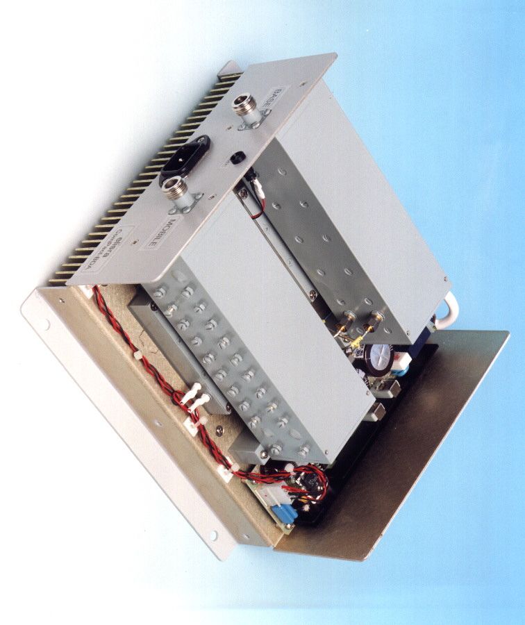
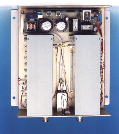
FCC ID: OIW CBDAESMR1W60 Exhibit 8 - Page 1 of 9 EXHIBIT 8: DESCRIPTION OF THE CIRCUIT FUNCTIONS AND BLOCK DIAGRAM ------ 47CFR 2.1033(4). The following is a brief description of the circuit functions and block diagram of the MW-CBDA-ESMR-1W60 Cellular Bi-Directional Amplifier/Booster. FCC ID: OIW CBDAESMR1W60 Exhibit 8 - Page 2 of 9 MW-CBDA-ESMR-1W60 BI-DIRECTIONAL AMPLIFIERS (COMPACT BDA) CIRCUIT FUNCTIONS DESCRIPTION FCC ID: OIW CBDAESMR1W60 Exhibit 8 - Page 3 of 9 TABLE OF CONTENTS PARAGRAPHPAGE No. BDA OVERVIEW4 BDA BLOCK DIAGRAM DESCRIPTION4 BDA RF BLOCK DIAGRAM DRAWING5 BDA DC CIRCUIT SCHEMATIC DIAGRAM5 BDA INSTALLATION6 POWER SUPPLY DESCRIPTION7 RF AMPLIFIER DESCRIPTION7 AGC FUNCTION DESCRIPTION8 MECHANICAL OUTLINE9 FCC ID: OIW CBDAESMR1W60 Exhibit 8 - Page 4 of 9 BDA OVERVIEW: The BDA assembly provides an exceptional repeater/booster performances to extend the coverage area of radio communications in buildings and RF shielded environments. Features such as high linearity power amplifiers are contributing for the overall improved system linearity performances. The unit is based on a duplexed path configuration, having sharp out of band attenuation for improved isolation between the receiving and transmitting paths. BDA BLOCK DIAGRAM DESCRIPTION: The BDA Downlink path receives the RF signals from base station amplifies and transmits them to the subscriber. The BDA Uplink path receives the RF signals from the subscriber amplifies and transmits them to the base station. Two duplexers frequency separate the signals to the proper amplifying path and isolate the two signals. BDA with AGC (Option A) The amplifiers in this BDA have an AGC feedback loop. The AGC circuit senses the output power and when it exceeds the preset level of +20 dBm it introduces more attenuation. In this manner the gain of the amplifier is reduced, its output power is limited to +20 dBm and the Intermodulation products are kept low. The AGC Dynamic range is 30 dB. FCC ID: OIW CBDAESMR1W60 Exhibit 8 - Page 5 of 9 BDA RF BLOCK DIAGRAM DOWN LINK RF AMPLIFIER BDA DC CIRCUIT SCHEMATIC DIAGRAM POWER SUPPLY UP LINK RF AMPLIFIER INPUT CONNECTOR ON / OFF LED DC AC AC (3 WIRE) Downlink Duplexer Uplink TO BASE STATION ANTENNA TO AREA ANTENNA (851-866 MHz) (806-821 MHz) (N-TYPE)(N-TYPE) RF AMPLIFIER AGC CIRCUIT (OPTION) DETECTER DETECTER RF AMPLIFIER COUPLER COUPLER Duplexer AGC CIRCUIT (OPTION) FCC ID: OIW CBDAESMR1W60 Exhibit 8 - Page 6 of 9 BDA INSTALLATION The BDA comes with a standard 3-wire male plug with phase, neutral and safety ground wires. The safety ground is connected to the BDA body. The AC power is only used to supply a high efficiency DC switching power supply. The power supply is CE and UL approved. The two amplifiers (Uplink and Downlink) and the Power On lamp use only DC power. DC power is fed to the amplifiers through feed-through connectors. The RF amplifiers have de-coupling capacitors in their circuits. These RF circuits (amplifiers and duplexers) use the BDA body as DC ground. The RF connection is made via two type “N” female connectors. The RF connector labeled “Base” must be connected to the antenna pointing to the base station. The RF connection labeled “Mobile” must be connected to the antenna pointing into the area to be covered by the repeater. The connections must be made through 50 ohms impedance cables. The isolation between the base station antenna and the mobile antenna should be at least 12 dB higher than the BDA gain. If the isolation were less than the BDA gain oscillation would start and would saturate the amplifier. Isolation few dB higher than the BDA gain cannot start oscillations but would causes gain ripple in the band. FCC ID: OIW CBDAESMR1W60 Exhibit 8 - Page 7 of 9 POWER SUPPLY DESCRIPTION Power Supply Type: Nemic-Lambda AC/DC switching power supply. Input Voltage Range: 85 to 265 VAC Output Voltage: +24 VDC Safety: Built to meet UL1950, CSA950, EN60950, DENTORI Conducted Noise: Built to meet EN55022, FCC Class B, VCCI-II RF AMPLIFIER DESCRIPTION The RF amplifier is made up of three amplifier modules housed in one package. The first two amplifier modules have 20 dB RF gain each. These amplifiers use Heterojunction Bipolar Transistor (HBT) technology. The DC to these amplifiers is provided using DC regulator housed in the package. The RF power amplifier at the output is LDMOS type; Lateral MOSFET Class A amplifier. It has a gain of 30 dB and power output of about 2 Watt. DC to the RF amplifier package is fed through RFI feedthrough solder pins FCC ID: OIW CBDAESMR1W60 Exhibit 8 - Page 8 of 9 AGC FUNCTION DESCRIPTION (AGC Option A only) The BDA with option A have AGC function. Their amplifier has a directional coupler and a detector at the output of the high power amplifier to monitor the output power. When a high signal is received the automatic level control detects the amplitude and sends a feedback signal to a voltage variable attenuator at the amplifier input which attenuates the signal level so that the output power of the amplifier does not exceed the preset limit. The AGC dynamic range is over 30 dB limited only by the dynamic range of the voltage variable attenuator own dynamic range. All these circuits are integral part of the amplifier and need no maintenance. FCC ID: OIW CBDAESMR1W60 Exhibit 8 - Page 9 of 9 BDA MECHANICAL OUTLINE
Test Report
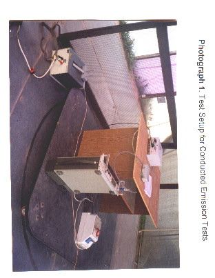
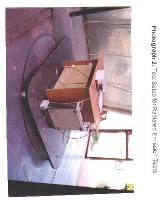
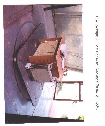
EMI TEST REPORT 9ELS029F FCC ID: OIW CBDAESMR1W60 Exhibit 9 - Page 1 of 19 EXHIBIT 9: MEASURED DATA ON CONDUCTED AND RADIATED EMISSIONS ------ 47CFR 2.1033(6). 1. POWER LINE CONDUCTED EMISSIONS ------ Pursuant 47 CFR 15.107. Measured data on conducted emissions per 47CFR 15.107 on AC power lines is the subject of attached Technical Report No.9ELS029F. 2. RADIATED EMISSIONS ------ Pursuant 47 CFR 15.109. Measured data on radiated emissions per 47CFR 15.109 is the subject of attached Technical Report No.9ELS029F. EMI TEST REPORT 9ELS029F FCC ID: OIW CBDAESMR1W60 Exhibit 9 - Page 2 of 19 ELECTROMAGNETIC COMPATIBILITY TEST REPORT Company Name: Elisra Electronic Systems Ltd. Equipment Under Test: Series MW-CBDA-ESMR-1W60 BDA Report I.D.Number: 9ELS029F.DOC Total number of pages (including this page):19 Date:11 March, 1999 EMI TEST Ltd. EMC Test Laboratory Moshav Hanniel P.O.B.65, D.N.Lev Hasharon, Israel, 42865 Phone:(972) 9-8987382 Fax:(972) 9-8987383 _________________________________________________________ This report must not be reproduced, except in full, without the written permission of EMI Test Ltd. This report relates only to the items tested. EMI TEST REPORT 9ELS029F FCC ID: OIW CBDAESMR1W60 Exhibit 9 - Page 3 of 19 Table of Contents: Description Page 1. General Information................................................................................. 4 2. Tests Summary. ...................................................................................... 5 3. Applicable Documents............................................................................. 6 4. Detailed Applicable EMC Requirements and Limits. ............................... 7 5. Procedures for Measuring RF Emissions from EUT................................ 8 5.1 AC Power line Conducted Emissions Measurements. ........................... 8 5.2 Radiated Emissions Measurements. ...................................................... 9 6. System Test Configuration. ..................................................................... 10 6.1 Product Description. ............................................................................... 10 6.2 The Tested Configuration. ...................................................................... 10 6.3 Clock frequencies................................................................................... 12 6.4 Cables Used During the Tests:............................................................... 12 6.5 Modifications Required for Compliance. ................................................. 12 7. Description of the Test Site. .................................................................... 13 8. List of Test Equipment Used. .................................................................. 14 9. Conducted Emission Data. ...................................................................... 15 10. Radiated Emission Data. ........................................................................ 15 11. Results of Conducted Emissions Tests. ................................................. 16 12. Results of Radiated Emission Tests....................................................... 16 13. Signatures. ............................................................................................. 17 14. Setup Photographs................................................................................. 18 List of Photographs Photo 1. Test setup, Conducted Emission Test........18 Photo 2. Test setup, Radiated Emission Test........19 EMI TEST REPORT 9ELS029F FCC ID: OIW CBDAESMR1W60 Exhibit 9 - Page 4 of 19 1. General Information. Applicant: Elisra Electm ronic Systems Ltd. Applicant Address: 48 Mivtza Kadesh St., Bene Beraq 51203, Israel Telephone: 972-3-6175639 FAX: 972-3-6175299 The testing was observed by the following applicant's personnel: Mr.Shmuel Auster Date of reception for testing: February 12, 1999 Dates of testing: February 12, 1999 February 17, 1999 Test Laboratory Location: EMI TEST Ltd, Moshav Hanniel, P.O.Box 65, D.N.Lev Hasharon, Israel 42865 Equipment Under Test: Series MW-CBDA-ESMR-1W60 Bi-Directional Amplifier Serial Numbers: 99021001 Mode of Operation: Up-Link and Down-Link Receiving and Transmitting modes Year of Manufacture: 1999 Applicable EMC Specification: Federal Communication Commission (FCC), Code of Federal Regulations 47, Ch. 1 (10-1-97 Edition) Part 15: Radio Frequency Devices, Sections 15.107 & 15.109, Class B EMI TEST REPORT 9ELS029F FCC ID: OIW CBDAESMR1W60 Exhibit 9 - Page 5 of 19 2. Tests Summary. EMI Test Laboratory has completed testing of Series MW-CBDA-ESMR-1W60 Bi- Directional Amplifier in accordance with the requirements of the FCC Part 15 Regulations for Class B equipment. The EUT has been found to comply with the conducted and radiated emission requirements of the FCC Part 15 Regulations for Class B equipment: Section 15.107:Limits of Mains Terminal Interference Voltage (Conducted Emission) in the 0.45MHz to 30MHz frequency range. Section 15.109:Limits of Radiated Interference Field Strength in the 30MHz to 9000MHz frequency range. EMI TEST REPORT 9ELS029F FCC ID: OIW CBDAESMR1W60 Exhibit 9 - Page 6 of 19 3. Applicable Documents. 3.1Federal Communication Commission (FCC), Code of Federal Regulations 47, Ch.1 (10-1-97 Edition), Part 15: Radio Frequency Devices, Sections 15.107 & 15.109. 3.2FCC/OET, Laboratory Measurement Procedures MP-4, July 1987, "FCC Procedures for Measuring RF Emissions from Computing Devices". 3.3FCC/Office of Science and Technology OST-55, August 1982, "Characteristics of Open Field Test Sites". 3.4FCC/OET, "FCC Procedure for Measuring Electromagnetic Emissions from Digital Devices", TP-5, March 1989. 3.5FCC/OET, "Understanding the FCC Regulations Concerning Computing Devices", OST-62, May 1984 3.6International Special Committee On Radio Interference (CISPR) Publication 16, First Edition 1993, Part 1. "Radio disturbance and immunity measuring apparatus". 3.7International Special Committee On Radio Interferen…
Text truncated - open the document above for the full version.
Test Report
FCC ID: OIW CBDA-ESMR-1W60 Exhibit 10 - Page 1 of 32 EXHIBIT 10: OCCUPIED BANDWIDTH DATA ------ Pursuant 47 CFR 2.989, 90.210(b), 90.210(g) and 90.691(a). Measured data on occupied bandwidth per 47CFR 2.989, 90.210(b), 90.210(g) and 90.691(a).is the subject of attached Technical Report No.9ELS029S. FCC ID: OIW CBDA-ESMR-1W60 Exhibit 10 - Page 2 of 32 ELECTROMAGNETIC COMPATIBILITY TEST REPORT Compliance with Occupied Bandwidth and Conducted Harmonics and Spurious Emissions Requirements of 47CFR Parts 2 and 90 Company Name:Elisra Electronic Systems Ltd. Equipment Under Test:Series MW-CBDA-ESMR-1W60 BDA Report I.D.Number:9ELS029S.DOC Total number of pages (including this page): 32 Date:29 March, 1999 EMI TEST Ltd. EMC Test Laboratory Moshav Hanniel, D.N.Lev Hasharon, Israel, 42865 Phone:(972) 9-8987382 Fax:(972) 9-8987383 _____________________________________________________________ This report must not be reproduced, except in full, without the written permission of EMI Test Ltd. This report relates only to the items tested. FCC ID: OIW CBDA-ESMR-1W60 Exhibit 10 - Page 3 of 32 Table of Content: Description Page 1. General Information.......................................................................... 5 2. Applicable Documents...................................................................... 6 3. Detailed Applicable Technical Requirements and Limits.................. 7 3.1 Occupied Bandwidth Requirements. ................................................ 7 3.1.1 Emission Mask B.............................................................................. 7 3.1.2 Emission Mask G. ............................................................................ 8 3.1.3 Emission Mask pursuant to 47CFR Section 90.691 ......................... 8 3.2 Conducted Spurious Emissions Requirements. ............................... 9 4. Test Setups and Test Procedures. ................................................... 10 4.1 Occupied Bandwidth Measurements................................................ 10 4.2 Measurements of Conducted Spurious Emissions at Antenna Ports. ..................................................................................................................... 12 4.2.1 Out-of-Band Harmonics and Spurious Emissions. ........................... 12 4.2 2 Measurement of In-Band Intermodulation Products. ........................ 13 5. Description of Equipment Under Test............................................... 15 5.1 Description of the Tested Equipment. .............................................. 15 5.2 Cables Used During the Tests: ........................................................ 16 5.3 Modifications Required for Compliance............................................ 16 6. List of Test Equipment Used. .......................................................... 17 7. Summary of Test Results. ................................................................ 18 7.1 Occupied Bandwidth Test. ............................................................... 18 7.2 Conducted Spurious and Harmonics Emissions in Antenna Ports Out-Of-Band Products...................................................................... 18 7.3 Conducted Spurious Emissions in Antenna Ports: In-Band Two-Tone Intermodulation Products................................... 18 8. Details of Test Results. .................................................................... 18 8.1 Occupied Bandwidth Test. ............................................................... 18 8.1.1 Up-Link (Mobile-to-Base) Transmit Mode......................................... 18 8.1.2 Down-Link (Base-to-Mobile) Transmit Mode. ................................... 19 FCC ID: OIW CBDA-ESMR-1W60 Exhibit 10 - Page 4 of 32 8.2 Conducted Spurious and Harmonics Emissions in Antenna Ports: Out-Of-Band Products...................................................................... 19 8.2.1 Up-Link (Mobile-to-Base) Transmit Mode......................................... 19 8.2.2 Down-Link (Base-to-Mobile) Transmit Mode. ................................... 19 8.3 Conducted Spurious Emissions in Antenna Ports: In-Band Two-Tone Intermodulation Products................................... 19 9. Signatures. ....................................................................................... 21 List of Figures. Figure A-1 Occupied Bandwidth Test in Up-Link Transmission Mode. F=813MHz, Pout = 100mWatt+20% = 120mWatt Performance relative to B-Mask per 47 CFR 90.210(b) 23 Figure A-2 Occupied Bandwidth Test in Up-Link Transmission Mode. F=813MHz, Pout = 100mWatt+20% = 120mWatt Performance relative to G-Mask per 47 CFR 90.210(g) 23 Figure A-3 Occupied Bandwidth Test in Up-Link Transmission Mode. F=813MHz, Pout = 100mWatt+20% = 120mWatt Performance relative to Mask per 47 CFR 90.691(a) 24 Figure A-4 Occupied Bandwidth Test in Down-Link Transmission Mode. F=858MHz, Pout = 100mWatt+20% = 120mWatt Performance relative to B-Mask per 47 CFR 90.210(b) 25 Figure A-5 Occupied Bandwidth Test in Down-Link Transmission Mode. F=858MHz, Pout = 100mWatt+20% = 120mWatt Performance relative to G-Mask per 47 CFR 90.210(g) 25 Figure A-6 Occupied Bandwidth Test in Down-Link Transmission Mode. F=858MHz, Pout = 100mWatt+20% = 120mWatt Performance relative to Mask per 47 CFR 90.691(a) 26 Figure B-1 Conducted Emissions at Antenna Port in Up-Link Transmission Mode. F=816MHz, Pout = 100mWatt+20% = 120mWatt 28 Figure B-2 Conducted Emissions at Antenna Port in Up-Link Transmission Mode. F=860MHz, Pout = 100mWatt+20% = 120mWatt 29 Figure C-1 Conducted Emissions at Antenna Port in Up-Link Transmission Mode. Two-Tone Intermodulation. Pout = 100mWatt 31 Figure C-2 Conducted Emissions at Antenna Port in Down-Link Transmission Mode. Two-Tone Intermodulation. Pout = 100mWatt 32 List of Tables: Table 1. Summary of Two-Tone Intermodulation Test Results.20 FCC ID: OIW CBDA-ESMR-1W60 Exhibit 10 - Page 5 of 32 1. General Information. Applicant: Elisra Electronic Systems Ltd. Applicant A…
Text truncated - open the document above for the full version.
Test Report
EMI Test Report 8ELS029T FCC ID: OIW CBDAESMR1W60 Exhibit 11 Page 1 of 26 EXHIBIT 11: RADIATED HARMONICS AND SPURIOUS EMISSIONS DATA ------ Pursuant 47 CFR 2.993. Measured data on occupied bandwidth per 47CFR 2.993.is the subject of attached Technical Report No.9ELS029T. EMI Test Report 8ELS029T FCC ID: OIW CBDAESMR1W60 Exhibit 11 Page 2 of 26 ELECTROMAGNETIC COMPATIBILITY TEST REPORT Compliance with Radiated Harmonics and Spurious Emissions Requirements of 47CFR Parts 2 and 90 Company Name:Elisra Electronic Systems Ltd. Equipment Under Test:Series MW-CBDA-ESMR-1W60 BDA Report I.D.Number:9ELS029T.DOC Total number of pages (including this page): 26 Date:19 March, 1999 EMI TEST Ltd. EMC Test Laboratory Moshav Hanniel, D.N.Lev Hasharon, Israel, 42865 Phone:(972) 9-8987382 Fax:(972) 9-8987383 ____________________________________________________ This report must not be reproduced, except in full, without the written permission of EMI Test Ltd. This report relates only to the items tested. EMI Test Report 8ELS029T FCC ID: OIW CBDAESMR1W60 Exhibit 11 Page 3 of 26 Table of Content: Description Page 1. General Information. ................... 5 2. Applicable Documents. ................... 6 3. Detailed Applicable EMC Requirements and Limits . ................ 7 4. Test Procedure for Measurement of RF Emissions from Equipment Under Test (EUT). ..................8 5. Description of Equipment Under Test and Support .................. 11 Equipment. .................. 11 6. Description of the Test Site. .................. 14 7. List of Test Equipment Used. .................. 15 8. Summary of Test Results. .................. 16 9. Details of Test Results. .................. 17 10. Signatures. .................. 20 Appendix A. Derivation of Standard Limit for FCC, Part 90 in the Frequency Range 0.8 to 9.0 GHz. ................. 21 EMI Test Report 8ELS029T FCC ID: OIW CBDAESMR1W60 Exhibit 11 Page 4 of 26 List of Figures. FIG. 1Test setup for the measurements of radiated emissions at frequencies up to the tenth harmonic of the carrier frequency 9 FIG.2Test setup for the test site calibration for FCC, Part 90 measurements 10 FIG.3The BDA block diagram11 FIG.4The tested configuration12 FIG.A-1Setup for the…
Text truncated - open the document above for the full version.
Contact Information
Applicant
Yaron Moas
Test Firm
Ordos/EMI Test LabYossi Ben-David
Technical Specifications
| # | Rule Parts | Frequency Range | Power Output | Emission |
|---|---|---|---|---|
| 2 | 22,9 | 851 MHz - 866 MHz | 100.00 mW | D7W |
Other Applications from Dekolink Wireless Ltd
OIWDCSA45047012CH
Mar 17, 2008Digital Channel Selective Amplifier-UHF (DCSA-UHF)
Equipment Class
TNB - Licensed Non-Broadcast Station Transmitter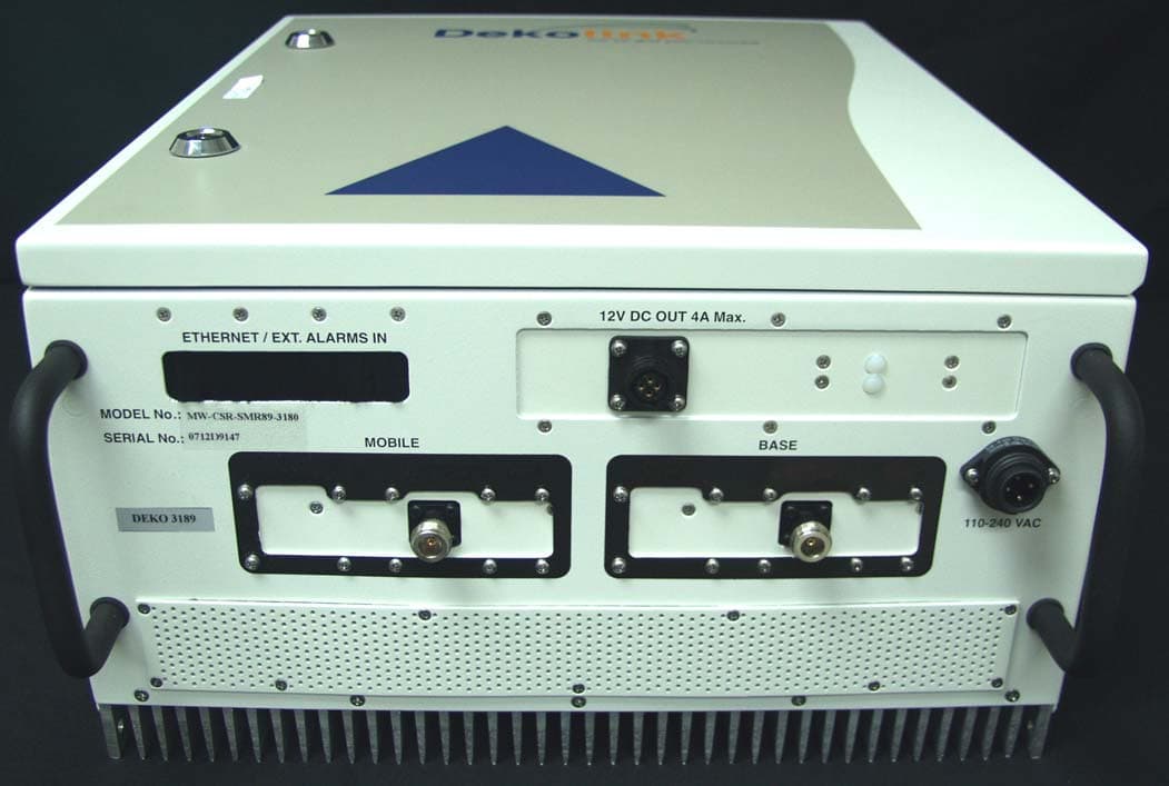
OIWCSRSMR893180
Mar 06, 2008DUAL BAND IDEN REPEATER
Equipment Class
TNB - Licensed Non-Broadcast Station Transmitter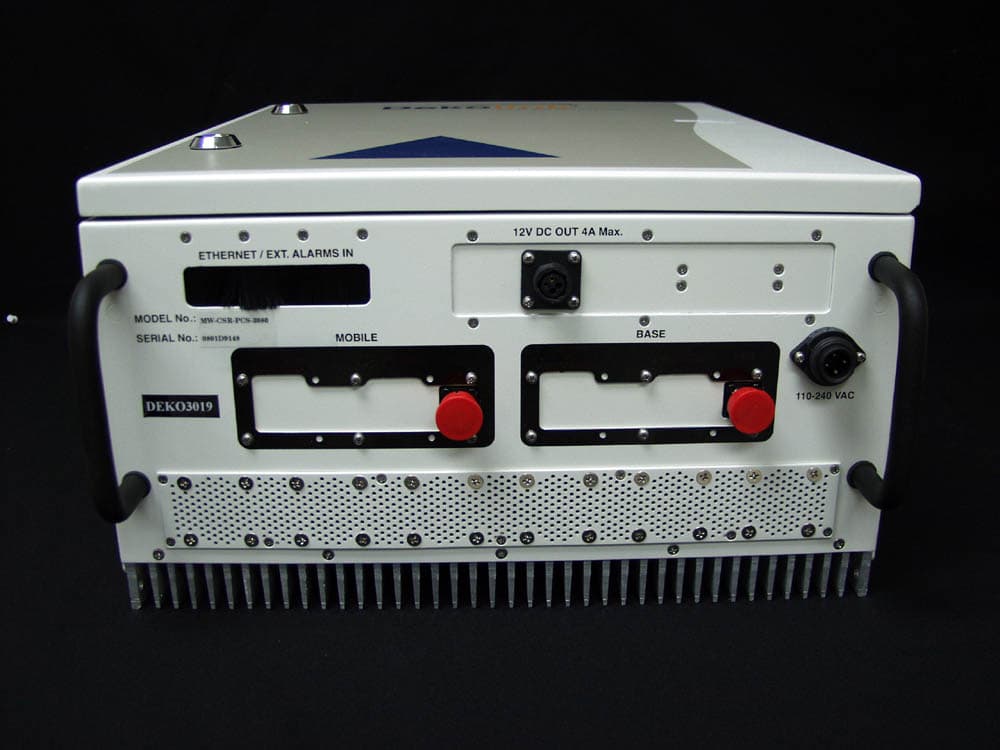
OIWCSRPCS3080
Mar 05, 2008CDMA MIDI REPEATER UNIT 80DB/30DBM WITH CCD
Equipment Class
PCB - PCS Licensed Transmitter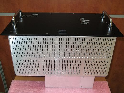
OIWDCSAU47020W90
Mar 03, 2008Digital Channel Selective Amplifier � UHF
Equipment Class
TNB - Licensed Non-Broadcast Station Transmitter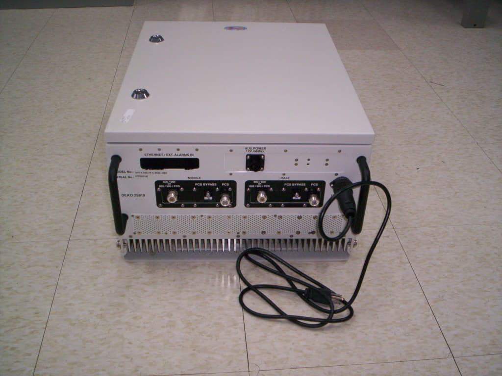
OIWCMRPCSSMR2580
Oct 31, 2007Multi-Band iDEN and WPCS Booster
Equipment Class
PCB - PCS Licensed Transmitter