OIWCBDAPCSAC1W65MW-CBDA-PCS-X-1W65-A Cellular Bi-Directional Ampli
Dekolink Wireless Ltd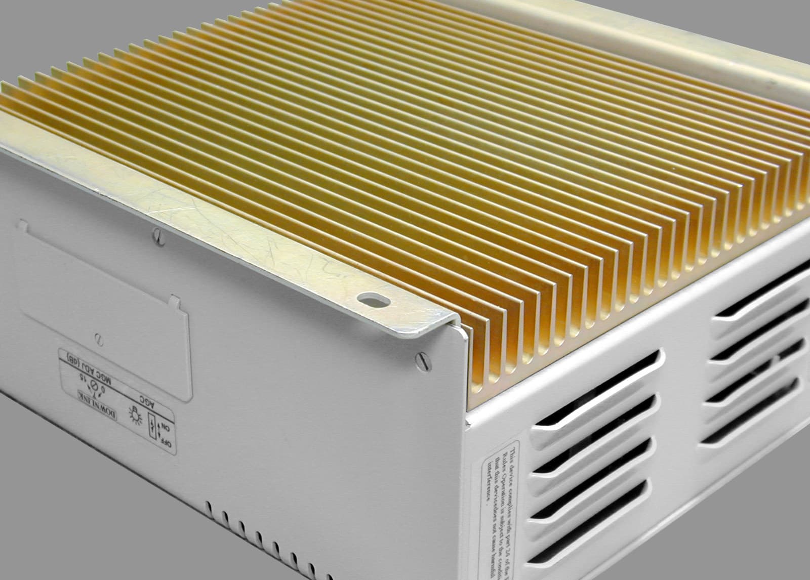
Click to zoom
Application Details
- Equipment Class
- AMP - Amplifier
- Date of Grant
- Jul 21, 2002
- Application Purpose
- Original Equipment
- Date of Application
- Jun 03, 2002
- Equipment Note
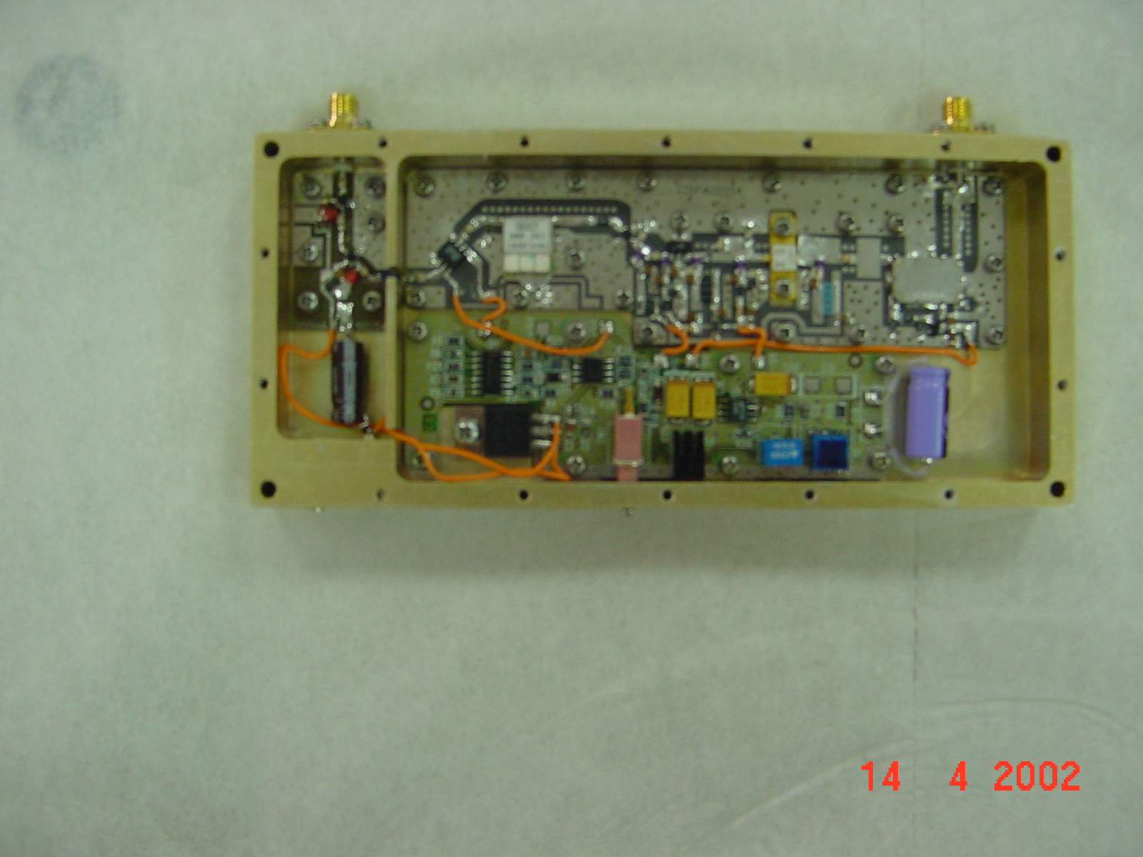
- MW-CBDA-PCS-X-1W65-A Cellular Bi-Directional Ampli
- Frequency Range
- 1930.00000000 - 1990.00000000
- Company
- Dekolink Wireless Ltd
- Country
- Israel
Documents & Files
Document Text
Text extracted from the exhibit documents filed with the FCC. Open a document above to read the original.
Users Manual
Dekolink WIRELESS Ltd. 16 Bazel St. Qiryat-Arieh Petah-Tikva, Israel, 49510 Tel- 972-3-9180-180 Fax-972-3-190-9180 e-mail: [email protected] web www.decolink.com INSTALLATION AND OPERATING INSTRUCTIONS FOR MW-CBDA-PCS-X-1W65-A CELLULAR BI-DIRECTIONAL AMPLIFIER Page 1 of 9 CBDA PCSX 1W65 Install.doc TABLE OF CONTENTS Dekolink WIRELESS Ltd. 16 Bazel St. Qiryat-Arieh Petah-Tikva, Israel, 49510 Tel- 972-3-9180-180 Fax-972-3-190-9180 e-mail: [email protected] web www.decolink.com PARAGRAPH PAGE No BDA OVERVIEW 3 BLOCK DAIGRAM DESCRIPTION 3 BDA OPERATION 4 AGC & MGC FUNCTION 5 RF EXPOSURE WARNING 6 ELECTRICAL SPECIFICATIONS 7 MECHANICAL SPECIFICATIONS 7 ENVIRONMENTAL CONDITIONS 7 LIST OF DRAWINGS DRAWING PAGE No BDA (WITH AGC) RF BLOCK DIAGRAM DRAWING 4 AGC & MGC CONTROL 5 MECHANICAL OUTLINE 8 Page 2 of 9 CBDA PCSX 1W65 Install.doc Dekolink WIRELESS Ltd. 16 Bazel St. Qiryat-Arieh Petah-Tikva, Israel, 49510 Tel- 972-3-9180-180 Fax-972-3-190-9180 e-mail: [email protected] web www.decolink.com BDA OVERVIEW: The Bi-Directional Amplifier (BDA) assembly provides an exceptional repeater/booster performances to extend the coverage area of radio communications in buildings and RF shielded environments. Features such as high linearity power amplifiers are contributing for the overall improved system linearity performances. The unit is based on a duplexed path configuration, having sharp out of band attenuation for improved isolation between the receiving and transmitting paths. BLOCK DIAGRAM DESCRIPTION: The CBDA Downlink path receives the RF signals from base station amplifies them and transmits them to the subscriber. The BDA Uplink path receives the RF signals from the subscriber amplifies them and transmits them to the base station. Two duplexers frequency separate the signals to the proper amplifying path and isolate the two signals. For each path there is an AGC amplifier. The amplifier has an AGC option switch. When switched on, the AGC circuit limits the amplifier output power. The AGC circuit senses the output power and introduces more attenuation, when the output power exceeds the preset level. This way the gain of the amplifier is reduced, its output power is limited and the intermodulations products are kept below the desired level. In this manner the output power cannot exceed the preset power and the IMD levels are always kept below –13 dBm. The AGC amplifier has a Power LED lamp that illuminates when the output power has reached the preset power limit. In addition the BDA has a trimmer that enables continuos reduction of the gain by over 15 dB. Page 3 of 9 CBDA PCSX 1W65 Install.doc Dekolink WIRELESS Ltd. 16 Bazel St. Qiryat-Arieh Petah-Tikva, Israel, 49510 Tel- 972-3-9180-180 Fax-972-3-190-9180 e-mail: [email protected] web www.decolink.com Duplexer Downlink Duplexer Uplink TO BASE STATION ANTENNA TO AREA ANTENNA (N-TYPE) (N-TYPE) AGC RF AMPLIFIER AGC CIRCUIT DETECTER AGC CIRCUIT DETECTER AGC RF AMPLIFIER COUPLER COUPLER MGC MGC BDA with AGC & MGC RF BLOCK DIAGRAM BDA OPERATION The RF connection is made via two type “N” female connectors. The RF connector labeled “Base” must be connected to the antenna pointing to the base station. The RF connection labeled “Mobile” must be connected to the antenna pointing into the area to be covered by the BDA. The isolation between the base station antenna and the mobile antenna should be at least 12 dB higher than the BDA gain. If the isolation were less than the BDA gain, oscillation would start and would saturate the amplifier. Isolation few dB higher than the BDA gain cannot start oscillations but would causes gain ripple in the band. Page 4 of 9 CBDA PCSX 1W65 Install.doc Dekolink WIRELESS Ltd. 16 Bazel St. Qiryat-Arieh Petah-Tikva, Israel, 49510 Tel- 972-3-9180-180 Fax-972-3-190-9180 e-mail: [email protected] web www.decolink.com AGC & MGC FUNCTION The BDA has AGC function. Their amplifier has a directional coupler and a detector at the output of the high power amplifier to monitor the output power. When a high signal is received the automatic level control detects the amplitude and sends a feedback signal to a voltage variable attenuator which attenuates the signal level so that the output power of the amplifier does not exceed the preset limit. The LED on the amplifier illuminates when the power out the amplifier is within the set limit (both when the AGC is On and when the AGC is OFF). The switch on the RF amplifier enables the AGC function. If the AGC is disabled then the amplifier gives maximum gain. MGC: The RF gain of the BDA can be reduced by about 15 dB using the continuos trimmer on the amplifier. The RF gain is at maximum when the trimmer is at anti-clockwise direction. To reduce the gain, turn the trimmer clockwise using a screwdriver. Turning it halfway would reduce the gain by 7.5 dB. The AGC and MGC functions for the uplink path are reached by opening a small cover located on the DBA side adjacent to the Mobile antenna port. For the downlink path the window is located on the side near the Base antenna port. Note: The BDA is shipped with the AGC switch in the OFF position and maximum RF gain. AGC & MGC CONTROL (Control Window Located at BDA sides) Gain Control Trimmer (MGC) Power Out LED AGC Enable Switch Page 5 of 9 CBDA PCSX 1W65 Install.doc Dekolink WIRELESS Ltd. 16 Bazel St. Qiryat-Arieh Petah-Tikva, Israel, 49510 Tel- 972-3-9180-180 Fax-972-3-190-9180 e-mail: [email protected] web www.decolink.com RF EXPOSURE WARNING In order to satisfy the FCC RF exposure requirements, you must ensure that the installation complies with the following: One antenna is connected via cable that has typical 1~10 dB attenuation (depends on the length of the cable) to the BDA BASE port. This antenna is installed outdoor and has very sharp beam (Yagi type or similar) pointed to the donor (BTS). This type of antenna has about 16 dBi gain. Typical specifications: gain: 8 dBd (=10.1 dBi), VSWR: better than 1.5:1 , Impedance…
Text truncated - open the document above for the full version.
Block Diagram
Dekolink WIRELESS Ltd. 16 Bazel St. Qiryat-Arieh Petah-Tikva, Israel, 49510 Tel- 972-3-9180-180 Fax-972-3-190-9180 e-mail: [email protected] web www.decolink.com Duplexer Downlink Duplexer Uplink TO BASE STATION ANTENNA TO AREA ANTENNA (N-TYPE) (N-TYPE) AGC RF AMPLIFIER AGC CIRCUIT DETECTER AGC CIRCUIT DETECTER AGC RF AMPLIFIER COUPLER COUPLER MGC MGC BDA with AGC & MGC RF BLOCK DIAGRAM BDA OPERATION The RF connection is made via two type “N” female connectors. The RF connector labeled “Base” must be connected to the antenna pointing to the base station. The RF connection labeled “Mobile” must be connected to the antenna pointing into the area to be covered by the BDA. The isolation between the base station antenna and the mobile antenna should be at least 12 dB higher than the BDA gain. If the isolation were less than the BDA gain, oscillation would start and would saturate the amplifier. Isolation few dB higher than the BDA gain cannot start oscillations but would causes gain ripple in the band. Page 4 of 9 CBDA PCSX 1W65 Install.doc
ID Label/Location Info
Dekolink WIRELESS Ltd. 16 Bazel St. Qiryat-Arieh Petah-Tikva, Israel, 49510 Tel- 972-3-9180-180 Fax-972-3-190-9180 e-mail: [email protected] web www.decolink.com FCC ID: OIW CBDAPCSAC1W65 LABLES Page 1 of 1 FCC ID CBDAPCS1W65 LABLES.doc
Operational Description
Dekolink WIRELESS Ltd. 16 Bazel St. Qiryat-Arieh Petah-Tikva, Israel, 49510 Tel- 972-3-9180-180 Fax-972-3-190-9180 e-mail: [email protected] web www.decolink.com ELECTRICAL SPECIFICATIONS: Uplink Downlink Frequency Range (MHz) See Table See Table CDMA Total Output Power +24 dBm typ +27 dBm typ AGC Factory Power Preset +24± 1dBm +27±1 dBm 3rd Order Output Intercept point +45 dBm typical +48 dBm typical 3rd Order IMD (dBc typ) 50 dBc @ two tones +20 dBm each 50 dBc @ two tones +23 dBm each Passband Gain @Min attenuation 65 dB min Passband Ripple ± 1.5 dB max Manual Attenuation Range (Continuous) 15 dB min Noise Figure 5.0 dB max Impedance level 50 ohms V.S.W.R In/Out 1.8 : 1 max AGC Selection By ON/OFF Switch AGC Attenuation Range 30 dB typical AGC LED Indication LED turn ON when power reaches AGC Set Power Level. (both at On and Off positions). Power Supply : 110/220V AC, 50-60 Hz /1A SYSTEM FREQUENCY RANGE: BLOCK Model No. Up Link Down Link A MW-CBDA-PCS-A-1W65-A 1850-1865 1930-1945 B MW-CBDA-PCS-B-1W65-A 1870-1885 1950-1965 C MW-CBDA-PCS-C-1W65-A 1895-1910 1975-1990 D MW-CBDA-PCS-D-1W65-A 1865-1870 1945-1950 E MW-CBDA-PCS-E-1W65-A 1885-1890 1965-1970 F MW-CBDA-PCS-F-1W65-A 1890-1895 1970-1975 Page 7 of 9 CBDA PCSX 1W65 Install.doc
Parts List/Tune Up Info
Dekolink WIRELESS Ltd. 16 Bazel St. Qiryat-Arieh Petah-Tikva, Israel, 49510 Tel- 972-3-9180-180 Fax-972-3-190-9180 e-mail: [email protected] web www.decolink.com 18 may 2002 FCC ID:OIWCBDAPCSAC1W65 PARTS LIST Part No Description Quantity PS001A0620/2800 CON.PWR-FILTER AC 6A 250V 50-400HZ 1 ZWS-50-15 PWR SUP. AC/DC IN:85-265V OUT;15V;3.5A 1 239-4 TERMINAL CRIMP HOUSING 1 300HA90350 HEAT SINK 1 300HA90250 BASE 1 300DB43000 BDA COMPACT COVER 1 300DA40850 BRACKET 1 SM86-11SMA(X2)-14.5CM CABLE ASSY L=14.5 CM SMA-P2 X2 CONN 1 SM86-11SMA(X2)-22CM CABLE ASSY L=22 CM SMA-P2 X2 CONN 1 SM86-11SMA(X2)-24CM CABLE ASSY L=24 CM SMA-P2 X2 CONN 1 SM86-11SMA(X2)-11CM CABLE ASSY L=11 CM SMA-P2 X2 CONN 1 SEE TABLE BELOW DIPLEXER FOR BDA 2 300RA32000 AMP PCS 1W60 15V(Up Link) 1 300RA33000 AMP PCS 2W65 15V(Down Link) 1 DIPLEXSERS TABLE Part No. BAND DOWNLINK FREQ. UPLINK FREQ. CD1898/15SK-E2/3 A 1930-1945 1850-1865 CD1918/15SK-E2/3 B 1950-1965 1870-1885 CD1942/15SK-E2/3 C 1975-1990 1895-1910 CD1908/5SK-E2/3 D 1945-1950 1865-1870 CD1927/5SK-E2/3 E 1965-1970 1885-1890 CD1932/5SK-E2/3 F 1970-1975 1890-1895 Page 1 of 1 Part List PCSX 1W65.doc
RF Exposure Info
Dekolink WIRELESS Ltd. 16 Bazel St. Qiryat-Arieh Petah-Tikva, Israel, 49510 Tel- 972-3-9180-180 Fax-972-3-190-9180 e-mail: [email protected] web www.decolink.com RF EXPOSURE WARNING In order to satisfy the FCC RF exposure requirements, you must ensure that the installation complies with the following: One antenna is connected via cable that has typical 1~10 dB attenuation (depends on the length of the cable) to the BDA BASE port. This antenna is installed outdoor and has very sharp beam (Yagi type or similar) pointed to the donor (BTS). This type of antenna has about 16 dBi gain. Typical specifications: gain: 8 dBd (=10.1 dBi), VSWR: better than 1.5:1 , Impedance: 50 ohm. The outdoor antenna must be installed to provide a minimum separation distance of 0.5 m (50 cm) from persons within the area. The second antenna is connected via cable that has typical 1~10 dB attenuation (depends on the length of the cable) to the CBDA MOBILE port. This type of antenna is omnidirecttional (isotropic), or wide beam, with 0 to 2 dBi typical gain and is installed and distributes indoor (in buildings, tunnels, basements, park lots, shopping centers etc.). Typical specifications: gain: 2 dBi, VSWR: better than 2:1 , Impedance: 50 ohm. The indoor antenna must be installed to provide a minimum separation distance of 0.2 m (20 cm) from persons within the area. Page 6 of 9 CBDA PCSX 1W65 Install.doc
Schematics
Dekolink WIRELESS Ltd. 16 Bazel St. Qiryat-Arieh Petah-Tikva, Israel, 49510 Tel- 972-3-9180-180 Fax-972-3-190-9180 e-mail: [email protected] web www.decolink.com Duplexer DOWNLINK AMPLIFIER Downlin k Duplexer UPLINK AMPLIFIER TO BASE STATION ANTENNA TO MOBILE ANTENNA POWER SUPPLY (N-TYPE) (N-TYPE) (STANDARD 3 WIRE) INPUT AC CONNECTOR DC 15V ELECTRICAL SCEMATICS Power Monitor PA AGC Power Monitor PA AGC FCC ID: OIW CBDAPCSAC1W65 Page 1 of 1 CBDA PCS 1W65 SCHEMATICS.doc
Test Report
Nemko Test Report No.: 2L0288RUS1 Applicant: DeKolink Wireless 16 Bazel St. Qiryat-Arieh Petah-Tikva Israel 49510 Equipment Under Test: Compact Bi Directional Amplifier In Accordance With: FCC Part 24, Subpart E Broadband PCS Repeaters Tested By: Nemko Dallas Inc. 802 N. Kealy Lewisville, Texas 75057-3136 Authorized By: David Light, Wireless Lab Supervisor Date: 5/28/02 Total Number of Pages: 51 Nemko Dallas FCC PART 24, SUBPART E BROADBAND PCS REPEATERS EQUIPMENT: Compact Bi Directional Amplifier PROJECT NO.: 2L0288RUS1 Table of Contents Section 1. Summary of Test Results...................................................................3 Section 2. General Equipment Specification.......................................................5 Section 3. RF Power Output................................................................................7 Section 4. Occupied Bandwidth..........................................................................8 Section 6. Field Strength of Spurious...............................................................34 Section 7. Frequency Stability..........................................................................40 Section 8. Test Equipment List.........................................................................41 ANNEX A - TEST DETAILS...............................................................................42 ANNEX B - TEST DIAGRAMS...........................................................................48 Page 2 of 51 Nemko Dallas FCC PART 24, SUBPART E BROADBAND PCS REPEATERS EQUIPMENT: Compact Bi Directional Amplifier PROJECT NO.: 2L0288RUS1 Section 1. Summary of Test Results Manufacturer: DeKolink Wireless Model No.: MW-CBDA-PCS-X-1W65 (X indicates PCS block of operation) Serial No.: 02039040/02039042 General: All measurements are traceable to national standards. These tests were conducted on a sample of the equipment for the purpose of demonstrating compliance with FCC Part 24, Subpart E. New Submission Production Unit Class II Permissive Change Pre-Production Unit THIS TEST REPORT RELATES ONLY TO THE ITEM (S) TESTED. THE FOLLOWING DEVIATIONS FROM, ADDITIONS TO, OR EXCLUSIONS FROM THE TEST SPECIFICATIONS HAVE BEEN MADE. See “ Summary of Test Data”. Nemko Dallas Inc. authorizes the above named company to reproduce this report provided it is reproduced in its entirety and for use by the company’s employees only. Any use which a third party makes of this report, or any reliance on or decisions to be made based on it, are the responsibility of such third parties. Nemko Dallas Inc. accepts no responsibility for damages, if any, suffered by any third party as a result of decisions made or actions based on this report. This report applies only to the items tested. Page 3 of 51 Nemko Dallas FCC PART 24, SUBPART E BROADBAND PCS REPEATERS EQUIPMENT: Compact Bi Directional Amplifier PROJECT NO.: 2L0288RUS1 Summary Of Test Data NAME OF TEST PARA. NO. SPEC. RESULT RF Power Output 24.232 100W Complies Occupied Bandwidth (CDMA) 24.238 Input/Output Complies Spurious Emissions at Antenna Terminals 24.238(a)-13 dBm Complies Field Strength of Spurious Emissions 24.238(a) -13 dBm E.I.R.P. Complies Frequency Stability 24.235 N /A Footnotes: (1) Modulation characteristics were not tested since the E.U.T. processes but does not produce a modulated waveform. Measurement uncertainty for each test configuration is expressed to 95% probability. Page 4 of 51 Nemko Dallas FCC PART 24, SUBPART E BROADBAND PCS REPEATERS EQUIPMENT: Compact Bi Directional Amplifier PROJECT NO.: 2L0288RUS1 Section 2. General Equipment Specification Supply Voltage Input: 115 VAC Frequency Bands: Downlink: Block A : 1930 – 1945 MHz Block D : 1945 – 1950 MHz Block B : 1950 – 1965 MHz Block E : 1965 – 1970 MHz Block F : 1970 – 1975 MHz Block C : 1975 – 1990 MHz Frequency Bands: Uplink: Block A : 1850 – 1865 MHz Block D : 1865 – 1870 MHz Block B : 1870 – 1885 MHz Block E : 1885 – 1890 MHz Block F : 1890 – 1895 MHz Block C : 1895 – 1910 MHz CDMA (G7W) Type of Modulation and Designator: System Gain (rated): 65 dB Output Impedance: 50 ohms Max Input: -45dBm Uplink 0.25W RF Output (Rated): Downlink Total:0.50W F1-F1 F1-F2 N/A Frequency Translation: Software Duplexer Full band Band Selection: Page 5 of 51 Nemko Dallas FCC PART 24, SUBPART E BROADBAND PCS REPEATERS EQUIPMENT: Compact Bi Directional Amplifier PROJECT NO.: 2L0288RUS1 Description of Operation The Compact Bi-Directional Amplifier (CBDA) assembly provides a repeater/booster to extend the coverage area of radio communications in buildings and RF shielded environments. The CBDA Downlink amplifier receives the RF signals from base station amplifies and transmits them to the subscriber. The BDA Uplink amplifier receives the RF signals from the subscriber amplifies and transmits them to the base station. Diagram Page 6 of 51 Nemko Dallas FCC PART 24, SUBPART E BROADBAND PCS REPEATERS EQUIPMENT: Compact Bi Directional Amplifier PROJECT NO.: 2L0288RUS1 Section 3. RF Power Output NAME OF TEST: RF Power Output PARA. NO.: 2.1046 TESTED BY: Kevin Rose DATE: 5/23/02 Test Results: Complies. Measurement Data: Modulation Type Per Channel Output Power (dBm) Downlink A CDMA 26.8 Uplink A CDMA 24.1 Downlink C CDMA 27.1 Uplink C CDMA 23.9 Equipment Used: 1464-1604-1052-1053 Measurement Uncertainty: +/- 1.7dB Temperature: 23 °C Relative Humidity: 38 % Page 7 of 51 Nemko Dallas FCC PART 24, SUBPART E BROADBAND PCS REPEATERS EQUIPMENT: Compact Bi Directional Amplifier PROJECT NO.: 2L0288RUS1 Section 4. Occupied Bandwidth NAME OF TEST: Occupied Bandwidth (CDMA) PARA. NO.: 2.1049 TESTED BY: Kevin Rose DATE: 5/23/02 Test Results: Complies. Test Data: See attached plot(s). Equipment Used: 1464-1604-1052-1053 Measurement Uncertainty: +/- 1.7dB Temperature: 21 °C Relative Humidity: 35 % Page 8 of 51 Nemko Dallas FCC PART 24, SUBPART E BROADBAND PCS REPEATERS EQUIPMENT: Compact Bi Directional Amplifier PROJECT NO.: 2L0288RUS1 Dallas Headquarters: 802 N. Kealy …
Text truncated - open the document above for the full version.
Test Report
Nemko Test Report No.:2L0288RUS1rev2 Applicant:DeKolink Wireless 16 Bazel St. Qiryat-Arieh Petah-Tikva Israel 49510 Equipment Under Test:Compact Bi Directional Amplifier In Accordance With:FCC Part 24, Subpart E Broadband PCS Repeaters Tested By: Nemko Dallas Inc. 802 N. Kealy Lewisville, Texas 75057-3136 Authorized By: Tom Tidwell, Wireless Group Manager Date: 7/16/2002 Total Number of Pages: 79 Nemko Dallas FCC PART 24, SUBPART E BROADBAND PCS REPEATERS EQUIPMENT: Compact Bi Directional Amplifier PROJECT NO.: 2L0288RUS1rev2 Page 2 of79 Table of Contents Section 1. Summary of Test Results .........................................................................3 Section 2. General Equipment Specification ............................................................5 Section 3. RF Power Output .....................................................................................7 Section 4. Occupied Bandwidth................................................................................8 Section 5. Spurious Emissions at Antenna Terminals ............................................25 Section 6. Field Strength of Spurious.....................................................................62 Section 7. Frequency Stability ................................................................................68 Section 8. Test Equipment List...............................................................................69 ANNEX A - TEST DETAILS .................................................................................70 ANNEX B - TEST DIAGRAMS.............................................................................76 Nemko Dallas FCC PART 24, SUBPART E BROADBAND PCS REPEATERS EQUIPMENT: Compact Bi Directional Amplifier PROJECT NO.: 2L0288RUS1rev2 Page 3 of79 Section 1.Summary of Test Results Manufacturer: DeKolink Wireless Model No.:MW-CBDA-PCS-X-1W65 (X indicates PCS block of operation) Serial No.:02039040/02039042 General:All measurements are traceable to national standards. These tests were conducted on a sample of the equipment for the purpose of demonstrating compliance with FCC Part 24, Subpart E. New SubmissionProduction Unit Class II Permissive ChangePre-Production Unit THIS TEST REPORT RELATES ONLY TO THE ITEM (S) TESTED. THE FOLLOWING DEVIATIONS FROM, ADDITIONS TO, OR EXCLUSIONS FROM THE TEST SPECIFICATIONS HAVE BEEN MADE. See “ Summary of Test Data”. Nemko Dallas Inc. authorizes the above named company to reproduce this report provided it is reproduced in its entirety and for use by the company’s employees only. Any use which a third party makes of this report, or any reliance on or decisions to be made based on it, are the responsibility of such third parties. Nemko Dallas Inc. accepts no responsibility for damages, if any, suffered by any third party as a result of decisions made or actions based on this report. This report applies only to the items tested. Nemko Dallas FCC PART 24, SUBPART E BROADBAND PCS REPEATERS EQUIPMENT: Compact Bi Directional Amplifier PROJECT NO.: 2L0288RUS1rev2 Page 4 of79 Summary Of Test Data NAME OF TEST PARA. NO.SPEC.RESULT RF Power Output24.232100WComplies Occupied Bandwidth (CDMA)24.238Input/OutputComplies Spurious Emissions at Antenna Terminals 24.238(a)-13 dBmComplies Field Strength of Spurious Emissions 24.238(a) -13 dBm E.I.R.P. Complies Frequency Stability24.235N /A Footnotes: (1) Modulation characteristics were not tested since the E.U.T. processes but does not produce a modulated waveform. Measurement uncertainty for each test configuration is expressed to 95% probability. Nemko Dallas FCC PART 24, SUBPART E BROADBAND PCS REPEATERS EQUIPMENT: Compact Bi Directional Amplifier PROJECT NO.: 2L0288RUS1rev2 Page 5 of79 Section 2.General Equipment Specification Supply Voltage Input: 115 VAC Frequency Bands:Downlink: Block A : 1930 – 1945 MHz Block D : 1945 – 1950 MHz Block B : 1950 – 1965 MHz Block E : 1965 – 1970 MHz Block F : 1970 – 1975 MHz Block C : 1975 – 1990 MHz Frequency Bands:Uplink: Block A : 1850 – 1865 MHz Block D : 1865 – 1870 MHz Block B : 1870 – 1885 MHz Block E : 1885 – 1890 MHz Block F : 1890 – 1895 MHz Block C : 1895 – 1910 MHz CDMAGSM (1M25G7W)(200KGXW) Type of Modulation and Designator: System Gain (rated): 65 dB Output Impedance: 50 ohms Max Input: -45dBm Uplink 0.25W RF Output (Rated): Downlink Total:0.50W F1-F1F1-F2N/A Frequency Translation: SoftwareDuplexerFull band Band Selection: Nemko Dallas FCC PART 24, SUBPART E BROADBAND PCS REPEATERS EQUIPMENT: Compact Bi Directional Amplifier PROJECT NO.: 2L0288RUS1rev2 Page 6 of79 Description of Operation The Compact Bi-Directional Amplifier (CBDA) assembly provides a repeater/booster to extend the coverage area of radio communications in buildings and RF shielded environments. The CBDA Downlink amplifier receives the RF signals from base station amplifies and transmits them to the subscriber. The BDA Uplink amplifier receives the RF signals from the subscriber amplifies and transmits them to the base station. Diagram Nemko Dallas FCC PART 24, SUBPART E BROADBAND PCS REPEATERS EQUIPMENT: Compact Bi Directional Amplifier PROJECT NO.: 2L0288RUS1rev2 Page 7 of79 Section 3.RF Power Output NAME OF TEST: RF Power OutputPARA. NO.: 2.1046 TESTED BY: Kevin Rose & David LightDATE: 5/23/02 Test Results:Complies. Measurement Data: Modulation TypeChannel Output Power (dBm) Channel Output Power (Watts) Downlink ACDMA 26.80.479 Uplink ACDMA 24.10.257 Downlink CCDMA 27.10.513 Uplink CCDMA 23.90.245 Downlink AGSM27.30.537 Uplink AGSM25.60.363 Downlink CGSM26.80.479 Uplink CGSM25.20.380 Note - Device was tested at +/- 15% nominal voltage with no effect on output power Equipment Used: 1464-1604-1052-1053-1036 Measurement Uncertainty: +/- 1.7dB Temperature: 23 °C Relative Humidity: 38% Nemko Dallas FCC PART 24, SUBPART E BROADBAND PCS REPEATERS EQUIPMENT: Compact Bi Directional Amplifier PROJECT NO.: 2L0288RUS1rev2 Page 8 of79 Section 4.Occupied Bandwidth NAME OF TEST: Occupied Bandwidth (CDMA)PAR…
Text truncated - open the document above for the full version.
Test Report
Nemko Dallas FCC PART 24, SUBPART E BROADBAND PCS REPEATERS EQUIPMENT: Compact Bi Directional Amplifier PROJECT NO.: 2L0288RUS1rev2 Page 5 of79 Section 2.General Equipment Specification Supply Voltage Input: 115 VAC Frequency Bands:Downlink: Block A : 1930 – 1945 MHz Block D : 1945 – 1950 MHz Block B : 1950 – 1965 MHz Block E : 1965 – 1970 MHz Block F : 1970 – 1975 MHz Block C : 1975 – 1990 MHz Frequency Bands:Uplink: Block A : 1850 – 1865 MHz Block D : 1865 – 1870 MHz Block B : 1870 – 1885 MHz Block E : 1885 – 1890 MHz Block F : 1890 – 1895 MHz Block C : 1895 – 1910 MHz CDMAGSM (1M25G7W)(200KGXW) Type of Modulation and Designator: System Gain (rated): 65 dB Output Impedance: 50 ohms Max Input: -45dBm Uplink 0.25W RF Output (Rated): Downlink Total:0.50W F1-F1F1-F2N/A Frequency Translation: SoftwareDuplexerFull band Band Selection:
Contact Information
Applicant
Yaron Moas
Technical Contact
Nemko Canada Inc.Ruby Dulmage
[email protected]613-737-9680
303 River Road, R.R. 5 · Ottawa, Ontario · Canada
Non-Technical Contact
Nemko Canada Inc.Ruby Dulmage
[email protected]613-737-9680
Test Firm
Nemko Canada Inc.Stuart Beck
Technical Specifications
| # | Rule Parts | Frequency Range | Power Output | Emission |
|---|---|---|---|---|
| 4 | 24E | 1.93 GHz - 1.99 GHz | 500.00 mW | G7W |
Other Applications from Dekolink Wireless Ltd
OIWDCSA45047012CH
Mar 17, 2008Digital Channel Selective Amplifier-UHF (DCSA-UHF)
Equipment Class
TNB - Licensed Non-Broadcast Station Transmitter
OIWCSRSMR893180
Mar 06, 2008DUAL BAND IDEN REPEATER
Equipment Class
TNB - Licensed Non-Broadcast Station Transmitter
OIWCSRPCS3080
Mar 05, 2008CDMA MIDI REPEATER UNIT 80DB/30DBM WITH CCD
Equipment Class
PCB - PCS Licensed Transmitter
OIWDCSAU47020W90
Mar 03, 2008Digital Channel Selective Amplifier � UHF
Equipment Class
TNB - Licensed Non-Broadcast Station Transmitter
OIWCMRPCSSMR2580
Oct 31, 2007Multi-Band iDEN and WPCS Booster
Equipment Class
PCB - PCS Licensed Transmitter