OIWCBDASMRPS8Bi-directional amplifier
Dekolink Wireless Ltd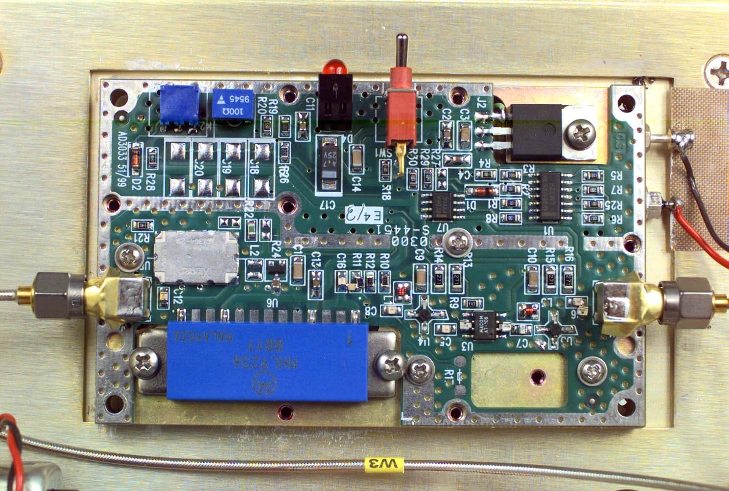
Click to zoom
Application Details
- Equipment Class
- AMP - Amplifier
- Date of Grant
- Jul 30, 2000
- Application Purpose
- Original Equipment
- Date of Application
- Apr 27, 2000
- Equipment Note
- Bi-directional amplifier
- Frequency Range
- 851.00000000 - 869.00000000
- Company
- Dekolink Wireless Ltd
- Country
- Israel
Documents & Files
Document Text
Text extracted from the exhibit documents filed with the FCC. Open a document above to read the original.
Users Manual
FCC ID: OIW CBDASMRPS8 Page 1 of 10 INSTALLATION AND OPERATING INSTRUCTIONS The following is a copy of Installation and Operating Instructions of the MW- CBDA-SMR-1W60PS-8 Cellular Bi-Directional Amplifier/Booster. FCC ID: OIW CBDASMRPS8 Page 2 of 10 INSTALLATION AND OPERATING INSTRUCTIONS FOR MW-CBDA-SMR-1W60PS-8 BI-DIRECTIONAL AMPLIFIER (COMPACT BDA) FCC ID: OIW CBDASMRPS8 Page 3 of 10 TABLE OF CONTENTS PARAGRAPHPAGE NO BDA OVERVIEW4 BDA BLOCK DIAGRAM DESCRIPTION4 BDA BLOCK DIAGRAM DRAWING5 ELECTRICAL SPECIFICATIONS6 MECHANICAL SPECIFICATIONS7 ENVIRONMENTAL CONDITIONS7 BDA CONNECTIONS8 PERIODIC MAINTENANCE8 DIAGNOSTIC GUIDE9 MECHANICAL OUTLINE10 FCC ID: OIW CBDASMRPS8 Page 4 of 10 BDA OVERVIEW: The BDA assembly provides an exceptional repeater/booster performances to extend the coverage area of radio communications in buildings and RF shielded environments. Features such as high linearity power amplifiers are contributing for the overall improved system linearity performances. The unit is based on a duplexed path configuration, having sharp out of band attenuation for improved isolation between the receiving and transmitting paths. BDA BLOCK DIAGRAM DESCRIPTION: The BDA Downlink path receives the RF signals from base station amplifies and transmits them to the subscriber. The BDA Uplink path receives the RF signals from the subscriber amplifies and transmits them to the base station. Two duplexers frequency separate the signals to the proper amplifying path and isolate the two signals. BDA w ith AGC (Option A) The amplifiers in this BDA have an AGC feedback loop. The AGC circuit senses the output power and when it exceeds the preset level of +20 dBm it introduces more attenuation. In this manner the gain of the amplifier is reduced, its output power is limited to +20 dBm and the Intermodulation products are kept low. The AGC Dynamic range is 30 dB. FCC ID: OIW CBDASMRPS8 Page 5 of 10 BDA BLOCK DIAGRAM MW-CBDA-SMR-1W60PS-8 Duplexer Downlink Duplexer Uplink TO BASE STATION ANTENNA TO AREA ANTENNA (N-TYPE) (N-TYPE) AGC RF AMPLIFIER AGC CIRCUIT DETECTER AGC CIRCUIT DETECTER AGC RF AMPLIFIER COUPLER COUPLER MGC MGC FCC ID: OIW CBDASMRPS8 Page 6 of 10 ELECTRICAL SPECIFICATIONS: Frequency Range : Up Link : 806 – 824 MHz : Down Link : 851 – 869 MHz Passband Gain @ min attenuation: 60 dB minimum Passband Ripple : ±1.5 dB typical Noise Figure @+25 °C at max gain : 6.0 dB max 3rd Order Intercept point: +45 dBm typical IMD @2 tone @+20 dBm/carrier: 50 dBc typical Isolation between Up/Down Link: 70 dB min Impedance Level: 50 Ohms VSWR In: 1.5 : 1 max Power Supply: 80 to 240 VAC; 50 to 60 Hz; @500 mA FCC ID: OIW CBDASMRPS8 Page 7 of 10 MECHANICAL SPECIFICATIONS: Size: 9.84 x 9.61 x 4.53 inch (250 x 244 x 115 mm) RF Connectors : N-type Female Weight: 10 Lbs. (5kg.) approx. ENVIRONMENTAL CONDITIONS: The unit is designed for indoor applications: Operating temperature: - 30 ° C to + 50 ° C Storage temperature: - 50 ° C to + 90 ° C FCC ID: OIW CBDASMRPS8 Page 8 of 10 BDA CONNECTIONS The BDA AC power is supplied through a standard 3-wire male plug with phase, neutral and safety ground wires. The AC power is only used to supply a high efficiency DC switching power supply. The two amplifiers (Uplink and Downlink) and the Power On lamp use only DC power. The RF connection is made via two type “N” female connectors. The RF connector labeled “Base” must be connected to the antenna pointing to the base station. The RF connection labeled “Mobile” must be connected to the antenna pointing into the area to be covered by the BDA. The connections must be made through 50 ohms impedance cables. The isolation between the base station antenna and the mobile antenna should be at least 12 dB higher than the BDA gain. If the isolation were less than the BDA gain, oscillation would start and would saturate the amplifier. Isolation few dB higher than the BDA gain cannot start oscillations but would causes gain ripple in the band. PERIODIC MAINTENANCE The BDA should provide long term, care free operation with no need of any periodic maintenance. The BDA has no user adjustments or alignments. The front panel lamp indicates power supply turn on. FCC ID: OIW CBDASMRPS8 Page 9 of 10 DIAGNOSTICS GUIDE As mentioned before the BDA should provide long term, care free operation with no need of any periodic maintenance. This section will cover possible problems that may show up after installation. a. Gain Reduction Possible causes: Bad RF cables and RF connections to antennas, Damaged antennas. b. Excessive Intermodulation or Spurious Possible causes: Amplifier oscillation caused by insufficient isolation. The isolation between two antennas is given by the equation: Isolation = 92.5 + 20 Log ( F x D ) – Gt – Gr F is frequency in GHz D is separation in Km Gt is the transmit antenna gain (at the direction of the receive antenna). Gr is the receive antenna gain (at the direction of the transmit antenna). For example at the SMR frequency the antenna isolation at 100 m separation is about 71 dB for omni antennas (0 dB gain). To increase isolation the antennas should have higher directivity and must be pointed away from each other. c. Occasional Drop-out of some Channels Possible causes: One channel with very strong power dominating the RF output of the amplifier. FCC ID: OIW CBDASMRPS8 Page 10 of 10 MECHANICAL OUTLINE
Users Manual
FCC ID: OIW CBDASMRPS8 Page 1 of 11 INSTALLATION AND OPERATING INSTRUCTIONS The following is a copy of Installation and Operating Instructions of the MW- CBDA-SMR-1W60PS-8 Cellular Bi-Directional Amplifier/Booster. FCC ID: OIW CBDASMRPS8 Page 2 of 11 INSTALLATION AND OPERATING INSTRUCTIONS FOR MW-CBDA-SMR-1W60PS-8 BI-DIRECTIONAL AMPLIFIER (COMPACT BDA) FCC ID: OIW CBDASMRPS8 Page 3 of 11 TABLE OF CONTENTS PARAGRAPHPAGE NO BDA OVERVIEW4 BDA BLOCK DIAGRAM DESCRIPTION4 BDA BLOCK DIAGRAM DRAWING5 ELECTRICAL SPECIFICATIONS6 MECHANICAL SPECIFICATIONS7 ENVIRONMENTAL CONDITIONS7 BDA CONNECTIONS8 PERIODIC MAINTENANCE8 DIAGNOSTIC GUIDE9 MECHANICAL OUTLINE10 RF EXPOSURE WARNING11 FCC ID: OIW CBDASMRPS8 Page 4 of 11 BDA OVERVIEW: The BDA assembly provides an exceptional repeater/booster performances to extend the coverage area of radio communications in buildings and RF shielded environments. Features such as high linearity power amplifiers are contributing for the overall improved system linearity performances. The unit is based on a duplexed path configuration, having sharp out of band attenuation for improved isolation between the receiving and transmitting paths. BDA BLOCK DIAGRAM DESCRIPTION: The BDA Downlink path receives the RF signals from base station amplifies and transmits them to the subscriber. The BDA Uplink path receives the RF signals from the subscriber amplifies and transmits them to the base station. Two duplexers frequency separate the signals to the proper amplifying path and isolate the two signals. BDA w ith AGC (Option A) The amplifiers in this BDA have an AGC feedback loop. The AGC circuit senses the output power and when it exceeds the preset level of +20 dBm it introduces more attenuation. In this manner the gain of the amplifier is reduced, its output power is limited to +20 dBm and the Intermodulation products are kept low. The AGC Dynamic range is 30 dB. FCC ID: OIW CBDASMRPS8 Page 5 of 11 BDA BLOCK DIAGRAM MW-CBDA-SMR-1W60PS-8 Duplexer Downlink Duplexer Uplink TO BASE STATION ANTENNA TO AREA ANTENNA (N-TYPE) (N-TYPE) AGC RF AMPLIFIER AGC CIRCUIT DETECTER AGC CIRCUIT DETECTER AGC RF AMPLIFIER COUPLER COUPLER MGC MGC FCC ID: OIW CBDASMRPS8 Page 6 of 11 ELECTRICAL SPECIFICATIONS: Frequency Range : Up Link : 806 – 824 MHz : Down Link : 851 – 869 MHz Passband Gain @ min attenuation: 60 dB minimum Passband Ripple : ±1.5 dB typical Noise Figure @+25 °C at max gain : 6.0 dB max 3rd Order Intercept point: +45 dBm typical IMD @2 tone @+20 dBm/carrier: 50 dBc typical Isolation between Up/Down Link: 70 dB min Impedance Level: 50 Ohms VSWR In: 1.5 : 1 max Power Supply: 80 to 240 VAC; 50 to 60 Hz; @500 mA FCC ID: OIW CBDASMRPS8 Page 7 of 11 MECHANICAL SPECIFICATIONS: Size: 9.84 x 9.61 x 4.53 inch (250 x 244 x 115 mm) RF Connectors : N-type Female Weight: 10 Lbs. (5kg.) approx. ENVIRONMENTAL CONDITIONS: The unit is designed for indoor applications: Operating temperature: - 30 ° C to + 50 ° C Storage temperature: - 50 ° C to + 90 ° C FCC ID: OIW CBDASMRPS8 Page 8 of 11 BDA CONNECTIONS The BDA AC power is supplied through a standard 3-wire male plug with phase, neutral and safety ground wires. The AC power is only used to supply a high efficiency DC switching power supply. The two amplifiers (Uplink and Downlink) and the Power On lamp use only DC power. The RF connection is made via two type “N” female connectors. The RF connector labeled “Base” must be connected to the antenna pointing to the base station. The RF connection labeled “Mobile” must be connected to the antenna pointing into the area to be covered by the BDA. The connections must be made through 50 ohms impedance cables. The isolation between the base station antenna and the mobile antenna should be at least 12 dB higher than the BDA gain. If the isolation were less than the BDA gain, oscillation would start and would saturate the amplifier. Isolation few dB higher than the BDA gain cannot start oscillations but would causes gain ripple in the band. PERIODIC MAINTENANCE The BDA should provide long term, care free operation with no need of any periodic maintenance. The BDA has no user adjustments or alignments. The front panel lamp indicates power supply turn on. FCC ID: OIW CBDASMRPS8 Page 9 of 11 DIAGNOSTICS GUIDE As mentioned before the BDA should provide long term, care free operation with no need of any periodic maintenance. This section will cover possible problems that may show up after installation. a. Gain Reduction Possible causes: Bad RF cables and RF connections to antennas, Damaged antennas. b. Excessive Intermodulation or Spurious Possible causes: Amplifier oscillation caused by insufficient isolation. The isolation between two antennas is given by the equation: Isolation = 92.5 + 20 Log ( F x D ) – Gt – Gr F is frequency in GHz D is separation in Km Gt is the transmit antenna gain (at the direction of the receive antenna). Gr is the receive antenna gain (at the direction of the transmit antenna). For example at the SMR frequency the antenna isolation at 100 m separation is about 71 dB for omni antennas (0 dB gain). To increase isolation the antennas should have higher directivity and must be pointed away from each other. c. Occasional Drop-out of some Channels Possible causes: One channel with very strong power dominating the RF output of the amplifier. FCC ID: OIW CBDASMRPS8 Page 10 of 11 MECHANICAL OUTLINE FCC ID: OIW CBDASMRPS8 Page 11 of 11 RF EXPOSURE WARNING: In order to satisfy the FCC RF exposure requirements, you must ensure that the installation complies with the following: One antenna is connected via cable that has 3~10 dB attenuation (depends on the length of the cable) to the CBDA BASE port. This antenna is installed outdoor and has very sharp beam (Yagi type or similar) pointed to the donor (BTS). This type of antenna has about 10 dBi gain. Typical specifications: (model ASPD2996): gain: 8dBd (=10.1dBi), VSWR: better than 1.5:1 , Impedance: 50 ohm, F/B ratio: 18 dB, E-plane Beamwidth: 47deg., H…
Text truncated - open the document above for the full version.
ID Label/Location Info
FCC ID: OIW CBDASMRPS8 Page 1 of 1 IDENTIFICATION LABEL ----- 47CFR 2.983(f). Pursuant 47CFR Section 2.983(f) see the Identification Label and Location Info. of the MW-CBDA-SMR-1W60PS-8 Cellular Bi-Directional Amplifier/Booster.
Operational Description
FCC ID: OIW CBDASMRPS8 DESCRIPTION OF THE CIRCUIT FUNCTIONS AND BLOCK DIAGRAM The following is a brief description of the circuit functions and block diagram of the MW-CBDA-SMR-1W60PS-8 Cellular Bi-Directional Amplifier/Booster. FCC ID: OIW CBDASMRPS8 MW-CBDA-SMR-1W60PS-8 BI-DIRECTIONAL AM PLIFIERS (COMPACT BDA) CIRCUIT FUNCTIONS DESCRIPTION FCC ID: OIW CBDASMRPS8 TABLE OF CONTENTS PARAGRAPHPAGE No. BDA OVERVIEW4 BDA BLOCK DIAGRAM DESCRIPTION4 BDA RF BLOCK DIAGRAM DRAWING5 BDA DC CIRCUIT SCHEMATIC DIAGRAM5 BDA INSTALLATION6 POWER SUPPLY DESCRIPTION7 RF AMPLIFIER DESCRIPTION7 AGC FUNCTION DESCRIPTION8 MECHANICAL OUTLINE9 FCC ID: OIW CBDASMRPS8 BDA OVERVIEW: The BDA assembly provides an exceptional repeater/booster performances to extend the coverage area of radio communications in buildings and RF shielded environments. Features such as high linearity power amplifiers are contributing for the overall improved system linearity performances. The unit is based on a duplexed path configuration, having sharp out of band attenuation for improved isolation between the receiving and transmitting paths. BDA BLOCK DIAGRAM DESCRIPTION: The BDA Downlink path receives the RF signals from base station amplifies and transmits them to the subscriber. The BDA Uplink path receives the RF signals from the subscriber amplifies and transmits them to the base station. Two duplexers frequency separate the signals to the proper amplifying path and isolate the two signals. BDA w ith AGC (Option A) The amplifiers in this BDA have an AGC feedback loop. The AGC circuit senses the output power and when it exceeds the preset level of +20 dBm it introduces more attenuation. In this manner the gain of the amplifier is reduced, its output power is limited to +20 dBm and the Intermodulation products are kept low. The AGC Dynamic range is 30 dB. FCC ID: OIW CBDASMRPS8 BDA RF BLOCK DIAGRAM Downlink Duplexer Uplink TO BASE STATION ANTENNA TO AREA ANTENNA (N-TYPE)(N-TYPE) RF AMPLIFIER AGC CIRCUIT (OPTION) DETECTER DETECTER RF AMPLIFIER COUPLER COUPLER Duplexer AGC CIRCUIT (OPTION) DOWN LINK RF AMPLIFIER BDA DC CIRCUIT SCHEMATIC DIAGRAM POWER SUPPLY UP LINK RF AMPLIFIER INPUT CONNECTOR ON / OFF LED DC AC AC (3 WIRE) FCC ID: OIW CBDASMRPS8 BDA INSTALLATION The BDA comes with a standard 3-wire male plug with phase, neutral and safety ground wires. The safety ground is connected to the BDA body. The AC power is only used to supply a high efficiency DC switching power supply. The power supply is CE and UL approved. The two amplifiers (Uplink and Downlink) and the Power On lamp use only DC power. DC power is fed to the amplifiers through feed-through connectors. The RF amplifiers have de-coupling capacitors in their circuits. These RF circuits (amplifiers and duplexers) use the BDA body as DC ground. The RF connection is made via two type “N” female connectors. The RF connector labeled “Base” must be connected to the antenna pointing to the base station. The RF connection labeled “Mobile” must be connected to the antenna pointing into the area to be covered by the repeater. The connections must be made through 50 ohms impedance cables. The isolation between the base station antenna and the mobile antenna should be at least 12 dB higher than the BDA gain. If the isolation were less than the BDA gain oscillation would start and would saturate the amplifier. Isolation few dB higher than the BDA gain cannot start oscillations but would causes gain ripple in the band. FCC ID: OIW CBDASMRPS8 POWER SUPPLY DESCRIPTION Power Supply Type: Nemic-Lambda AC/DC switching power supply. Input Voltage Range: 85 to 265 VAC Output Voltage: +24 VDC Safety: Built to meet UL1950, CSA950, EN60950, DENTORI Conducted Noise: Built to meet EN55022, FCC Class B, VCCI-II RF AMPLIFIER DESCRIPTION The RF amplifier is made up of three amplifier modules housed in one package. The first two amplifier modules have 20 dB RF gain each. These amplifiers use Heterojunction Bipolar Transistor (HBT) technology. The DC to these amplifiers is provided using DC regulator housed in the package. The RF power amplifier at the output is LDMOS type; Lateral MOSFET Class A amplifier. It has a gain of 30 dB and power output of about 2 Watt. DC to the RF amplifier package is fed through RFI feedthrough solder pins FCC ID: OIW CBDASMRPS8 AGC FUNCTION DESCRIPTION (AGC Option A only) The BDA with option A have AGC function. Their amplifier has a directional coupler and a detector at the output of the high power amplifier to monitor the output power. When a high signal is received the automatic level control detects the amplitude and sends a feedback signal to a voltage variable attenuator at the amplifier input which attenuates the signal level so that the output power of the amplifier does not exceed the preset limit. The AGC dynamic range is over 30 dB limited only by the dynamic range of the voltage variable attenuator own dynamic range. All these circuits are integral part of the amplifier and need no maintenance. FCC ID: OIW CBDASMRPS8 BDA MECHANICAL OUTLINE
Parts List/Tune Up Info
FCC ID: OIW CBDASMRPS8 PARTS LIST: Part NoDescription Quantity PS001A0620/2800CON.PWR-FILTER AC 6A 250V 50-400HZ 1 ZWA-50-24PWR SUP. AC/DC IN:85-265V OUT;24V;2.1A 1 2139-6TERMINAL CRIMP HOUSING1 300CA31000HEAT SINK1 300CA32000BDA COMPACT CHASSIS1 300CA30250BDA COMPACT COVER1 SM86-11SMA(X2)-14.5CMCABLE ASSY L=14.5 CM SMA-P2 X2 CONN 1 SM86-11SMA(X2)-22CMCABLE ASSY L=22 CM SMA-P2 X2 CONN 1 SM86-11SMA(X2)-24CMCABLE ASSY L=24 CM SMA-P2 X2 CONN 1 SM86-11SMA(X2)-11CMCABLE ASSY L=11 CM SMA-P2 X2 CONN 1 CD838/19SK-A2/3DIPLEXER 806-824/851-869 MHZ FOR BDA 2 300CA32100AMP 2W2
RF Exposure Info
Below is the information which has been provided by the manufacturer: 2a).The CBDA is used for indoor/in-building application. It is located in an isolated and remote place, out of public proximity. 2b). The downlink antenna is connected via cable that has 3~10 dB attenuation (depends on the length of the cable) to the CBDA BASE port. This antenna is installed outdoor and has very sharp beam (Yagi type or similar) pointed to the donor (BTS). This type of antenna has about 10 dBi gain. Typical specifications: (model ASPD2996): gain: 8dBd (=10.1dBi), VSWR: better than 1.5:1 , Impedance: 50 ohm, F/B ratio: 18 dB, E-plane Beamwidth: 47deg., H-plane Beamwidth: 58 deg. 2c). The uplink antenna is connected via cable that has 2~6 dB attenuation (depends on the length of the cable) to the CBDA MOBILE port. This type of antenna is omnidirectional (isotropic) with 0 to 2 dBi gain and is installed indoor (buildings, tunnels, basements, park lots, shopping centers etc.). This antenna is installed usually on the ceiling. Typical specifications: (Kathrein model No. 741 572): gain: 2dBi, VSWR: better than 2:1 ,Impedance: 50 ohm, Polarization: Vertical. Based on this information, we believe that this device meets the categorical exclusion requirement of 2.1091. From the information given above, we have determined that this equipment meets the Limits for General Population/Uncontrolled Exposure of 1.1310 at a minimum distance of 0.3m for the outdoor antenna and at a distance of 0.1m for the indoor antenna. I trust that this information will enable you to complete the submission process.
RF Exposure Info
It seems that in my previous message I used incorrectly the "uplink" and "downlink" terms.. Below is what the text should have read: 1. We sell our CBDA products as an "amplifier component" to our customers, which are providers like Nextel and others. Our CBDAs passed all the needed tests of radiated and conducted emissions . Our customers can put terminations (...if they wish) on the input/output ports or connect them to antennas. It is their responsibility to stand all the standards, rules etc. since they design the system, select the components (antennas, cables) and make the installation. 2. I talked with Frank Coperich and was asked to collect information about the typical antenna gain, cable loss and installation requirements. This information is for both models, the PS8 and the PS9: 2a).The CBDA is used for indoor/in-building application. It is located in an isolated and remote place, out of public proximity. 2b). One antenna is connected via cable that has 3~10 dB attenuation (depends on the length of the cable) to the CBDA BASE port. This antenna is installed outdoor and has very sharp beam (Yagi type or similar) pointed to the donor (BTS). This type of antenna has about 10 dBi gain. Typical specifications: (model ASPD2996): gain: 8dBd (=10.1dBi), VSWR: better than 1.5:1 , Impedance: 50 ohm, F/B ratio: 18 dB, E-plane Beamwidth: 47deg., H-plane Beamwidth: 58 deg. 2c). The second antenna is connected via cable that has 2~6 dB attenuation (depends on the length of the cable) to the CBDA MOBILE port. This type of antenna is omnidirectional (isotropic) with 0 to 2 dBi gain and is installed and distributes indoor (in buildings, tunnels, basements, park lots, shopping centers etc.). This antenna is installed usually on the ceiling. Typical specifications: (Kathrein model No. 741 572): gain: 2dBi, VSWR: better than 2:1 ,Impedance: 50 ohm, Polarization: Vertical. Based on this information, we believe that this device meets the categorical exclusion requirement of 2.1091. From the information given above, we have determined that this equipment meets the Limits for General Population/Uncontrolled Exposure of 1.1310 at a minimum distance of 0.3m for the outdoor antenna and at a distance of 0.1m for the indoor antenna. I trust that this information will enable you to complete the submission process.
RF Exposure Info
FCC ID: OIW CBDASMRPS8 RF EXPOSURE WARNING: In order to satisfy the FCC RF exposure requirements, you must ensure that the installation complies with the following: One antenna is connected via cable that has typical 1~10 dB attenuation (depends on the length of the cable) to the CBDA BASE port. This antenna is installed outdoor and has very sharp beam (Yagi type or similar) pointed to the donor (BTS). This type of antenna has about 10 dBi gain. Typical specifications: gain: 8dBd (=10.1dBi), VSWR: better than 1.5:1 , Impedance: 50 ohm. You must maintain a minimum distance of 0.3m from the outdoor antenna to people within the area. The second antenna is connected via cable that has typical 1~10 dB attenuation (depends on the length of the cable) to the CBDA MOBILE port. This type of antenna is omnidirectional (isotropic), or wide beam, with 0 to 2 dBi typical gain and is installed and distributes indoor (in buildings, tunnels, basements, park lots, shopping centers etc.). Typical specifications: gain: 2dBi, VSWR: better than 2:1, Impedance: 50 ohm. You must maintain a minimum distance of 0.1m from the indoor antenna to people within the area.
RF Exposure Info
_______________ FCC ID: OIW CBDASMRPS8 RF EXPOSURE WARNING: In order to satisfy the FCC RF exposure requirements, you must ensure that the installation complies with the following: One antenna is connected via cable that has typical 1~10 dB attenuation (depends on the length of the cable) to the CBDA BASE port. This antenna is installed outdoor and has very sharp beam (Yagi type or similar) pointed to the donor (BTS). This type of antenna has about 10 dBi gain. Typical specifications: gain: 8dBd (=10.1dBi), VSWR: better than 1.5:1 , Impedance: 50 ohm. The indoor antenna must be installed to provide a minimum separation distance of 0.3m (30cm) from persons within the area. The second antenna is connected via cable that has typical 1~10 dB attenuation (depends on the length of the cable) to the CBDA MOBILE port. This type of antenna is omnidirectional (isotropic), or wide beam, with 0 to 2 dBi typical gain and is installed and distributes indoor (in buildings, tunnels, basements, park lots, shopping centers etc.). Typical specifications: gain: 2dBi, VSWR: better than 2:1, Impedance: 50 ohm. The indoor antenna must be installed to provide a minimum separation distance of 0.2m (20cm) from persons within the area.
RF Exposure Info
_______________ FCC ID: OIW CBDASMRPS8 RF EXPOSURE WARNING: In order to satisfy the FCC RF exposure requirements, you must ensure that the installation complies with the following: One antenna is connected via cable that has typical 1~10 dB attenuation (depends on the length of the cable) to the CBDA BASE port. This antenna is installed outdoor and has very sharp beam (Yagi type or similar) pointed to the donor (BTS). This type of antenna has about 10 dBi gain. Typical specifications: gain: 8dBd (=10.1dBi), VSWR: better than 1.5:1 , Impedance: 50 ohm. The outdoor antenna must be installed to provide a minimum separation distance of 0.3m (30cm) from persons within the area. The second antenna is connected via cable that has typical 1~10 dB attenuation (depends on the length of the cable) to the CBDA MOBILE port. This type of antenna is omnidirectional (isotropic), or wide beam, with 0 to 2 dBi typical gain and is installed and distributes indoor (in buildings, tunnels, basements, park lots, shopping centers etc.). Typical specifications: gain: 2dBi, VSWR: better than 2:1, Impedance: 50 ohm. The indoor antenna must be installed to provide a minimum separation distance of 0.2m (20cm) from persons within the area.
Schematics
FCC ID: OIW CBDASMRPS8 ELECTRICAL SCHEMATIC: Duplexer Downlink Duplexer Uplink TO BASE STATION ANTENNA TO AREA ANTENNA (N-TYPE) (N-TYPE) RF AMPLIFIER RF AMPLIFIER POWER SUPPLY INPUT CONNECTOR ON / OFF LED DC AC AC (3 WIRE) (+24 VDC)
Test Report
Master: ktlPT90PLMR Date: April 10, 2000 KTL Test Report:0R02415 Applicant:Elisra Electronics System Inc. 48 Mitzva Kadesh Street Bene Beraq, Israel 51203 Equipment Under Test:MW-CBDA-SMR-1W60PS-8 (E.U.T.) FCC ID:OIWCBDASMRPS8 In Accordance With:FCC Part 90, Subpart I Private Land Mobile Repeater Tested By:KTL Ottawa Inc. 3325 River Road, R.R. 5 Ottawa, Ontario K1V 1H2 Authorized By: R. Grant, Wireless Group Manager Date: Total Number of Pages:30 KTL Ottawa FCC PART 90, SUBPART I PRIVATE LAND MOBILE REPEATER PROJECT NO.: 0R02415 EQUIPMENT: MW-CBDA-SMR-1W60PS-8 FCC ID: OIWCBDASMRPS8 Page 2 of 26 Table of Contents Section 1. Summary of Test Results.......................................................................................... 3 Section 2. General Equipment Specification ........................................................................... 5 Section 3. RF Power Output .....................................................................................................6 Section 4. Occupied Bandwidth................................................................................................ 7 Section 5. Spurious Emissions at Antenna Terminals........................................................... 16 Section 6. Field Strength of Spurious Emissions................................................................... 25 Section 7. Test Equipment List ............................................................................................... 26 Annex A Test Diagrams ........................................................................................................ A1 KTL Ottawa FCC PART 90, SUBPART I PRIVATE LAND MOBILE REPEATER PROJECT NO.: 0R02415 EQUIPMENT: MW-CBDA-SMR-1W60PS-8 FCC ID: OIWCBDASMRPS8 Page 3 of 26 Section 1.Summary of Test Results General All measurements are traceable to national standards. These tests were conducted on a sample of the equipment for the purpose of demonstrating compliance with FCC Part 90, Subpart I. New SubmissionProduction Unit Class II Permissive ChangePre-Production Unit AMP Equipment Code THIS TEST REPORT RELATES ONLY TO THE ITEM(S) TESTED. THE FOLLOWING DEVIATIONS FROM, ADDITIONS TO, OR EXCLUSIONS FROM THE TEST SPECIFICATIONS HAVE BEEN MADE. See “ Summary of Test Data”. NVLAP LAB CODE: 100351-0 TESTED BY: _____________________________________ DATE: ___________________ Kevin Carr, Technologist KTL Ottawa Inc. authorizes the above named company to reproduce this report provided it is reproduced in its entirety and for use by the company’s employees only. Any us e whic h a third p a rty ma k e s o f this re p o rt, o r a ny re lia nc e o n o r d e c is io ns to b e ma d e b a s e d o n it, a re the re s p o ns ib ility of such third parties. KTL Ottawa Inc. accepts no responsibility fo r d a ma ge s , if a ny, s uffe re d b y a ny third p a rty a s a re s ult o f d e c is io ns ma d e o r a c tio ns b a s e d o n this re p o rt. This report applies only to the items tested. KTL Ottawa FCC PART 90, SUBPART I PRIVATE LAND MOBILE REPEATER PROJECT NO.: 0R02415 EQUIPMENT: MW-CBDA-SMR-1W60PS-8 FCC ID: OIWCBDASMRPS8 Page 4 of 26 Summary Of Test Data Name Of TestPara. No.Result RF Power Output2.1046Complies Audio Frequency Response2.1047Not Applicable Audio Low-Pass Filter Response2.1047Not Applicable Modulation Limiting2.1047Not Applicable Occupied Bandwidth2.1049Complies Spurious Emissions at Antenna Terminals2.1051Complies Field Strength of Spurious Emissions2.1053Complies Frequency Stability2.1055Not Applicable Transient Frequency Behavior——Not Applicable Footnotes For N/A’s: Indoor Temperature: 24 °C Humidity:30 % Outdoor Temperature: 15 °C Humidity:30 % . KTL Ottawa FCC PART 90, SUBPART I PRIVATE LAND MOBILE REPEATER PROJECT NO.: 0R02415 EQUIPMENT: MW-CBDA-SMR-1W60PS-8 FCC ID: OIWCBDASMRPS8 Page 5 of 26 Section 2.General Equipment Specification Manufacturer: Elisra Electronic Systems Ltd. Model No.: MW-CBDA-SMR-1W60PS-8 Serial No.: 00041001 Date Received In Laboratory: April 3, 2000 KTL Identification No.: Item #1 Transmitter Supply Voltage Input: 120 VAC, 60 Hz Frequency Range: UL-806 - 824 MHz DL-851-869 MHz Tunable Bands: 2 Type(s) of Modulation: F3E, F1E, F1D Gain: 60 dB Nominal Output Impedance: 50 ohm RF Power Output (rated): Total Composite: 27.0 dBm Operator Selection of Operating Frequency: None Power Output Adjustment Capability: AGC. The RF output power per channel decreases as the number of channels increases according to the following formula: P = N W 50.0 Where N=Number of Channels Frequency Translation: None Band Selection: None KTL Ottawa FCC PART 90, SUBPART I PRIVATE LAND MOBILE REPEATER PROJECT NO.: 0R02415 EQUIPMENT: MW-CBDA-SMR-1W60PS-8 FCC ID: OIWCBDASMRPS8 Page 6 of 26 Section 3.RF Power Output Para. No.: 2.1046 Test Performed By: Kevin Carr Date of Test: April 18, 2000 Minimum Standard: Para. No. 90.205 ± 1 dB Rated Test Results: Complies. The measured RF power output is within 0 dB of the manufacturer’s rating of RF power…
Text truncated - open the document above for the full version.
Contact Information
Applicant
Yaron Moas
Technical Contact
Non-Technical Contact
KTL Ottawa Inc.Ruby C Dulmage
[email protected]800-563-6336
Test Firm
Nemko Canada Inc.Stuart Beck
Technical Specifications
| # | Rule Parts | Frequency Range | Power Output | Emission |
|---|---|---|---|---|
| 6 | 9 | 851 MHz - 869 MHz | 500.00 mW | F1D |
Other Applications from Dekolink Wireless Ltd
OIWDCSA45047012CH
Mar 17, 2008Digital Channel Selective Amplifier-UHF (DCSA-UHF)
Equipment Class
TNB - Licensed Non-Broadcast Station Transmitter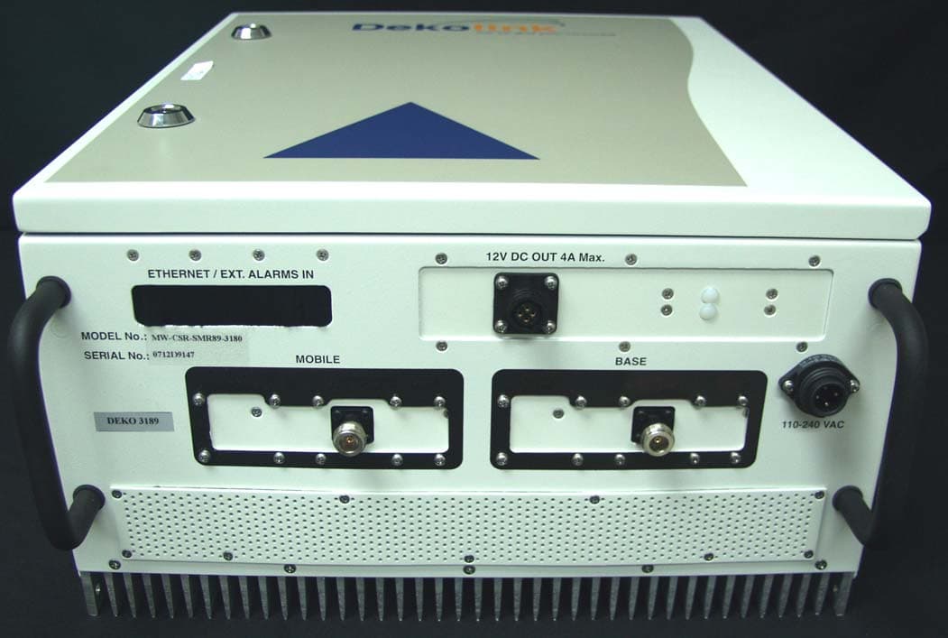
OIWCSRSMR893180
Mar 06, 2008DUAL BAND IDEN REPEATER
Equipment Class
TNB - Licensed Non-Broadcast Station Transmitter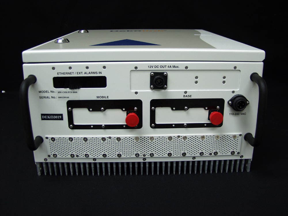
OIWCSRPCS3080
Mar 05, 2008CDMA MIDI REPEATER UNIT 80DB/30DBM WITH CCD
Equipment Class
PCB - PCS Licensed Transmitter
OIWDCSAU47020W90
Mar 03, 2008Digital Channel Selective Amplifier � UHF
Equipment Class
TNB - Licensed Non-Broadcast Station Transmitter
OIWCMRPCSSMR2580
Oct 31, 2007Multi-Band iDEN and WPCS Booster
Equipment Class
PCB - PCS Licensed Transmitter