OIWCSR800AB25W90Bi-Directional Booster
Dekolink Wireless Ltd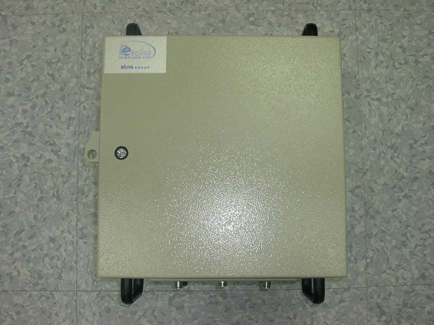
Click to zoom
Application Details
- Equipment Class
- TNB - Licensed Non-Broadcast Station Transmitter
- Date of Grant
- Apr 14, 2005
- Application Purpose
- Original Equipment
- Date of Application
- Apr 14, 2005
- Equipment Note
- Bi-Directional Booster
- Frequency Range
- 869.00000000 - 894.00000000
- Company
- Dekolink Wireless Ltd
- Country
- Israel
Documents & Files
Document Text
Text extracted from the exhibit documents filed with the FCC. Open a document above to read the original.
Users Manual
© Dekolink Wireless Ltd.—All Rights Reserved Revision 1.0 ABOUT THIS MANUAL This Product Manual provides the following information: A description of the CDMA Repeater • • • • • A functional description of the Repeater A description of its main modules Procedures for setup, configuration and checking the proper functioning of the CDMA Repeater Maintenance and troubleshooting procedures TO WHOM IT IS INTENDED: This Product Manual is intended for experienced technicians and engineers. It is assumed that the customers installing, operating, and maintaining Dekolink CDMA Repeaters are familiar with the basic functionality of repeaters. DEKOLINK WIRELESS LTD. PRODUCT MANUAL CELLULAR REPEATER NOTICE Confidential - Authorized Customer Use This document may be used in its complete form only and is solely for the use of Dekolink Wireless Ltd. employees and authorized Dekolink Wireless Ltd. channels or customers. The material herein is proprietary to Dekolink Wireless Ltd. Any unauthorized reproduction, use or disclosure of any part thereof is strictly prohibited. All trademarks and registered trademarks are the property of their respective owners. DISCLAIMER OF LIABILITY Contents herein are current as of the date of publication. Dekolink Wireless Ltd. reserves the right to change the contents without prior notice. The information furnished by Dekolink Wireless Ltd. in this document is believed to be accurate and reliable. However, Dekolink Wireless Ltd. assumes no responsibility for its use. In no event shall Dekolink Wireless Ltd. be liable for any damage resulting from loss of data, loss of use, or loss of profits and Dekolink Wireless Ltd. further disclaims any and all liability for indirect, incidental, special, consequential or other similes damages. This disclaimer of liability applies to all products, publications and services during and after the warranty period. EXCLUSIVE REMEDIES The remedies provided herein are the Buyer’s sole and exclusive remedies. Dekolink Wireless Ltd. shall not be viable for any direct, incidental, or consequential damages, whether based on contract, tort, or any legal theory. Dekolink Wireless Ltd. – Elisra Group International Headquarters 16 Bazel St., Kiryat-Arieh, Petah-Tikvah 49001 ISRAEL Tel.: +972 3 918-0180 Fax: +972 3 918-0190 E-mail: [email protected] Website: www.dekolink.com © Dekolink Wireless Ltd Publication No.: 311 -2005 Rev. 1.0 Page b Proprietary Data Pub. 311-2005 Rev. 1.0 CELLULAR REPEATER PRODUCT MANUAL DEKOLINK WIRELESS LTD. SAFETY WARNINGS AND ADMONISHMENTS Throughout this manual, important safety warnings and admonishments are included to warn of possible hazards to persons or equipment. A safety warning identifies a possible hazard and then describes what may happen if the hazard is not avoided. The safety warnings – in the form of Dangers, Warnings and Cautions must be followed at all times. These warnings are flagged by the use of a warning icon, usually the triangular alert icon seen below. The exclamation point within the triangular alert icon is intended to warn the operator or service personnel of operation and maintenance from factors elating to the product and its operating environment, which could pose a safety hazard. GENERAL SAFETY WARNINGS CONCERNING USE OF THIS SYSTEM Always observe standard safety precautions during installation, operation and maintenance of this product. Only a qualified and authorized personnel should carry out adjustment, maintenance or repairs to the components of this equipment. Danger: Electrical Shock This equipment is usually installed outdoors. Wet conditions increase the potential for receiving an electric shock when installing or using electrically powered equipment. To prevent electrical shock when installing or modifying the system power wiring, disconnect the wiring at the power source before working with uninsulated wires or terminals. Caution: RF Exposure Installation of an antenna must comply with the FCC RF exposure requirements. Refer to paragraph 4.2. Pub. 311-2005 Rev. 1.0 Proprietary Data Page c DEKOLINK WIRELESS LTD. PRODUCT MANUAL CELLULAR REPEATER G LOSSARY The following is a list of abbreviations and terms used throughout this document. Abbreviation/Term Definition AGC Automatic Gain Control ALC Automatic Level Control ATR Acceptance Test Report DAS Distributed Antenna System DL Downlink Downlink The path covered from the Base Transceiver Station (BTS) to the subscribers/service area via the repeater ESD Electro-Static Discharge CDMA Code Domain Multiple Access IF Intermediate Frequency IP3 Third order Intercept Point MN Model Number NMT Network Management Tool PLL Phased Locked Loop POTS Plain Old Telephone System RF Radio Frequency RMT Repeater Management Tool SALC Smart-ALC (Automatic Level Control) SQE Signal Quality Estimate UL Uplink Uplink The path covered from the subscribers/service area to the Base Transceiver Station (BTS) via the repeater VSWR Voltage Standing Wave Ratio Page d Proprietary Data Pub. 311-2005 Rev. 1.0 DEKOLINK WIRELESS LTD. PRODUCT MANUAL IDEN REPEATER CONTENTS 1. Introduction..............................................................................................1 1.1 General........................................................................................................................1 1.2 Applications.................................................................................................................1 1.3 Features.......................................................................................................................1 1.4 Models and Frequencies...............................................................................................1 1.5 Specifications...............................................................................................................2 1.5.1 General.........................................................................................................2 1.5.2 Electrical Specific…
Text truncated - open the document above for the full version.
Cover Letter(s)
Nemko Canada Inc. I would like to confirm that I have a copy of section 90.219 & 22.383 for in-building/booster operation and our boosters comply with these rules. Best Regards, David Levy, Technical Support Manager Dekolink Wireless Ltd. 16 Bazel St. Qiryat-Arieh Petah-Tikva, Israel, 49510 Tel- 972-3-9180179 Fax-972-3-9180190
External Photos
MW-CSR-800AB-25W90 Photos FRONT SIDE A SIDE B BACK BOTTOM TOP INTERNAL VIEW
ID Label/Location Info
FCC ID Label for CSR-800AB-25W90
Parts List/Tune Up Info
Feb.13.2005 Tune up procedure for CSR 1. General 1.1. This Procedure is intended to calibrate the repeater so that the customer can set ALC level by assigning power value (dBm) in the “Max Power” box on the RMT, “Parameters and Control “ screen. 1.2. This procedure is conducted during the test procedure in the manufacturer’s premises. Customer has no access to this procedure. 2. Preparations 2.1. Connect to unit using RMS (see Manual). 2.2. Press Ctrl+P and Enter Technician password. 2.3. Press “ToolsÆ Open Param Loader” to get the tune up screen (see arrow below): 1 Download screen appears: 2.4. Press “ Write Parameters to Unit”. And wait for download to complete 2 2.5. Press “General” Tab GENERALALC Downlink AGC Uplink AGC 2.5.1. Set Downlink ALC On/Off to “0” 2.5.2. Set Uplink ALC On/Off to “0” 2.5.3. Press "ALC Calib " tab, the following window appears: 3 DL Power Value FWD UL Power Value FWD 3. Downlink ALC Calibration 3.1. Connect the unit to Test equipment as follows: S.Analyzer RF IN 30dB PED 30dB PED Signal Generator RF OUT RF Cable RF Cable iDEN Digital Reapeter BaseMobile * A Power Meter may be connected instead of Spectrum Analyzer 4 3.2. Set the input power to receive 38 dBM at the repeater’s MOBILE output. Sximate value for 37 dBm output). Read at 3.4. eieved in REG 0 (approximate value for 36 3.5. of 35, 34, to 26 4. . Uplink ALC Calibration pment as follows: A Power Meter may be connected instead of Spectrum Analyzer 3.3. Set DLPower Value FWD to 37. et REG 0 (upper list) to 230 (appro the output power, if output power is higher then 37 dBm, decrease the number in the register, if the power is lower, increase the number. Repe until 37 dBm output power is achieved. Set DLPower Value FWD to 36. St REG 1 to the same number ach dBm output). Read the output power, if output power is higher then 36 dBm, decrease the number in the register, if the power is lower, increase the number. Repeat until 36 dBm output power is achieved. Repeat the above procedure for DL Power Value FWD related to REG 2 to REG 11 accordingly, for output power 35 to 26 dBm respectively. 4.1. Connect the unit to Test equi S.Analyzer RF IN 30dB PED 30dB PED Signal Generator RF OUT RF Cable RF Cable Reapeter BaseMobile iDEN * 5 4.2. Set the input power to receive 25 dBM at the repeater’s BASE output. 4.3. Set ULPower Value FWD to 24. ead is higher then 24 dBm, decrease the 4.4. d in REG 0 (approximate value for 23 wer, if output power is higher then 23 dBm, 4.5. r 22 to 13 dBm Set REG 0 ( lower list) to 130 (approximate value for 24 dBm output). R the output power, if output power number in the register, if the power is lower, increase the number. Repeat until 30 dBm output power is achieved. Set ULPower Value FWD to 23. Set REG 1 to the same number achieve dBm output). Read the output po decrease the number in the register, if the power is lower, increase the number. Repeat until 23 dBm output power is achieved. Repeat the above procedure for UL Power Value FWD of 22, 21, to 13 related to REG 2 to REG 11 accordingly, for output powe respectively. 6
Parts List/Tune Up Info
Amplifiers operating voltage – 28 Vdc Uplink Power amplifier Supply current – 0.65 A Downlink power amplifier Supply current: 1.35 A
RF Exposure Info
Prediction of MPE limit at a given distance MW-CSR-800AB-25W90, with Indoor DownLink AntennaEquation from page 18 of OET Bulletin 65, Edition 97-01where: S = power density P = power input to the antennaG = power gain of the antenna in the direction of interest relative to an isotropic radiatorR = distance to the center of radiation of the antenna Maximum peak output power at antenna input terminal: 36.00 (dBm) Maximum peak output power at antenna input terminal: 3981.071706 (mW) Antenna gain (typical): 2 (dBi) Maximum antenna gain: 1.584893192 (numeric) Prediction distance: 30 (cm) Prediction frequency: 869 (MHz) MPE limit for uncontrolled exposure at prediction frequency: 0.579333333 (mW/cm^2) Power density at prediction frequency: 0.557889 (mW/cm^2) Maximum allowable antenna gain: 2.163808909 (dBi) Margin of Compliance: 0.163808909 (dB) 2 4 R PG S π =
RF Exposure Info
Prediction of MPE limit at a given distance MW-CSR-800AB-25W90, with Outdoor DownLink AntennaEquation from page 18 of OET Bulletin 65, Edition 97-01where: S = power density P = power input to the antennaG = power gain of the antenna in the direction of interest relative to an isotropic radiatorR = distance to the center of radiation of the antenna Maximum peak output power at antenna input terminal: 36.00 (dBm) Maximum peak output power at antenna input terminal: 3981.071706 (mW) Antenna gain(typical): 10 (dBi) Maximum antenna gain: 10 (numeric) Prediction distance: 100 (cm) Prediction frequency: 869 (MHz) MPE limit for uncontrolled exposure at prediction frequency: 0.579333333 (mW/cm^2) Power density at prediction frequency: 0.316804 (mW/cm^2) Maximum allowable antenna gain: 12.62138381 (dBi) Margin of Compliance: 2.621383814 2 4 R PG S π =
RF Exposure Info
Prediction of MPE limit at a given distance MW-CSR-800AB-25W90, with UpLink AntennaEquation from page 18 of OET Bulletin 65, Edition 97-01where: S = power density P = power input to the antennaG = power gain of the antenna in the direction of interest relative to an isotropic radiatorR = distance to the center of radiation of the antenna Maximum RF output power of uplink transmitter: 25.00 (dBm) Minimum cable loss between transmitter and antenna input: 2.00 (dB) Maximum peak output power at antenna input terminal: 23.00 (dBm) Maximum peak output power at antenna input terminal: 199.5262315 (mW) Maximum Antenna gain (typical): 20 (dBi) Maximum antenna gain: 100 (numeric) Prediction distance: 75 (cm) Prediction frequency: 824 (MHz) MPE limit for uncontrolled exposure at prediction frequency: 0.549333333 (mW/cm^2) Power density at prediction frequency: 0.28 (mW/cm^2) Maximum allowable antenna gain: 22.89 (dBi) Margin of Compliance: 2.89 (dB) 2 4 R PG S π =
Test Report
Master: Generic FCC Date: October 16, 2001 Test Report: 5W40259 Applicant: Dekolink Wireless Ltd. 16 Bazel St, Qiryat Arieh Petah-Tikva, 49510 Israel Equipment Under Test: MW-CSR-800AB-25W90 (EUT) FCC ID: OIWCSR800AB25W90 In Accordance With: FCC Part 22, Subpart H Tested By: Nemko Canada Inc. 303 River Road, R.R. 5 Ottawa, Ontario K1V 1H2 Authorized By: Jason Nixon, Telecommunications Specialist Date: 24 March 2005 Total Number of Pages: 54 Nemko Canada Inc. PROJECT NO.: 5W40259 FCC PART 22, SUBPART H EQUIPMENT: MW-CSR-800AB-25W90 Page 2 of 54 Table of Contents Section 1. Summary of Test Results ..........................................................................................3 Section 2. General Equipment Specification .............................................................................5 Section 3. RF Power Output ......................................................................................................7 Section 4. Occupied Bandwidth...............................................................................................11 Section 5. Spurious Emissions at Antenna Terminals .............................................................18 Section 6. Field Strength of Spurious Emissions.....................................................................51 Section 7. Block Diagrams .......................................................................................................52 Section 8. Test Equipment List .................................................................................................54 Nemko Canada Inc. PROJECT NO.: 5W40259 FCC PART 22, SUBPART H EQUIPMENT: MW-CSR-800AB-25W90 Page 3 of 54 Section 1. Summary of Test Results General All measurements are traceable to national standards. These tests were conducted on a sample of the equipment for the purpose of demonstrating compliance with FCC Part 22, Subpart H. THIS TEST REPORT RELATES ONLY TO THE ITEM(S) TESTED. TESTED BY: ______________________________ DATE: 24 March 2005 Roman Kuleba, EMC/Wireless Test Specialist Nemko Canada Inc. authorizes the above named company to reproduce this report provided it is reproduced in its entirety and for use by the company’s employees only. Nemko Canada Inc., a testing laboratory, is accredited by the Standards Council of Canada. The tests included in this report are within the scope of this accreditation. Any use which a third party makes of this report, or any reliance on or decisions to be made based on it, are the responsibility of such third parties. Nemko Canada Inc. accepts no responsibility for damages, if any, suffered by any third party as a result of decisions made or actions based on this report. This report applies only to the items tested. Nemko Canada Inc. PROJECT NO.: 5W40259 FCC PART 22, SUBPART H EQUIPMENT: MW-CSR-800AB-25W90 Page 4 of 54 Summary Of Test Data Name Of Test Para. No. Result RF Power Output 22.913(a) Complies Occupied Bandwidth 22.917(c) Complies Spurious Emissions at Antenna Terminals 22.917 Complies Field Strength of Spurious Emissions 22.917 Complies Frequency Stability 22.355 Complies Notes: 1. Modulation characteristics were not tested since the tested equipment does not modulate or demodulate the carrier (i.e. the EUT processes the signal but does not produce a modulated waveform). 2. The tested equipment uses the same LO for frequency conversion; therefore the transmitted signal is identical in frequency to the received signal. This was verified by measuring the transmitted (output) signal frequency with a frequency counter that was phase-locked to a signal generator used to generate input RF signal. Measured frequency deviation was 0 Hz and the EUT was deemed to comply with frequency stability requirement. 3. Installation guidelines to be followed as well as recommended types of antennas and safe separation distances needed to meet FCC RF exposure requirements are provided by manufacturer in Section 4 on pages 11–12 of EUT’s Product and Installation Manual (Revision 1.0). Testing Environment Conditions: Indoor Conditions: Temperature: 23°C Humidity: 10% Outdoor Conditions: Temperature: 5°C Humidity: 40% Nemko Canada Inc. PROJECT NO.: 5W40259 FCC PART 22, SUBPART H EQUIPMENT: MW-CSR-800AB-25W90 Page 5 of 54 Section 2. General Equipment Specification Manufacturer: Dekolink Wireless Ltd. Model No.: MW-CSR-800AB-25W90 Serial No.: 0501D034 Date Received In Laboratory: March 8, 2005 Nemko Identification No.: 5W40259, Items No. 1-3 (See Nemko Shipping and Receiving Report) Supply Voltage: 110 – 220 VAC Frequency Range: UpLink: 824 – 849 MHz DownLink: 869 – 894 MHz RF Output Power (Rated): UpLink: 0.25 W (24.00 dBm) DownLink: 4.00 W (36.00 dBm) RF Output Power (Measured): See: Section 3 Maximum Gain: UpLink: 90 dB DownLink: 90 dB Emission Designator: CDMA GSM TDMA (NADC) (F9W) (GXW) (DXW) Nemko Canada Inc. PROJECT NO.: 5W40259 FCC PART 22, SUBPART H EQUIPMENT: MW-CSR-800AB-25W90 Page 6 of 54 Description of operation Dekolink MW-CSR-800AB-25W90 is an Outdoor CDMA Repeater. The block diagram showed in Figure 1 below illustrates the overall functionality of the repeater. The EUT is based on a duplexed path configuration, having sharp out of band attenuation filters to improve the isolation between the receiving and transmitting paths. In addition it employs advanced up/down conversion Intermediate Frequency (IF) Surface Acoustic Waves (SAW) filtering architecture in each path for better spectrum purity. The Channeler module (blue colored) consists of dual Radio Frequency (RF) Up/Down Converter sub-modules for Downlink and Uplink paths. The Channeler amplifies the received RF signals and converts them into an intermediate frequency (IF). The IF outputs are connected to a SAW Filter. The IF outputs are converted back to the original RF frequencies. Figure 1: Nemko Canada Inc. PROJECT NO.: 5W40259 FCC PART 22, SUBPART H EQUIPMENT: MW-CSR-800AB-25W90 Page 7 of 54 Section 3. RF Power Output Test Performed By: Roman Ku…
Text truncated - open the document above for the full version.
Test Report
MW-CSR-800AB-25W90 Frequency Response Plots
Test Setup Photos
Nemko Canada Inc. PROJECT NO.: 5W40259 FCC PART 22, SUBPART H EQUIPMENT: MW-CSR-800AB-25W90 Page 51 of 54 Section 6. Field Strength of Spurious Emissions Para. No.: 2.1053 Test Performed By: Roman Kuleba Date of Test: March 15, 2005 Minimum Standard: 22.917(e): -13dBm Test Results: Complies. Measurement Data: Pre-scan test on the EUT for radiated emissions between 30 MHz and 18 GHz in both, vertical and horizontal polarization was performed in a shielded chamber. No signals above noise level were detected. Detailed Setup Photos: EUT - Front View: EUT - Rear View: Pre-scan in Shielded Chamber:
Contact Information
Applicant
Yaron Moas
Technical Contact
Test Firm
Nemko Canada Inc. (Ottawa)Charles Neal
Technical Specifications
| # | Rule Parts | Frequency Range | Power Output | Emission | Tolerance |
|---|---|---|---|---|---|
| 6 | 22H | 869 MHz - 894 MHz | 4 W | DXW | Amp |
Other Applications from Dekolink Wireless Ltd
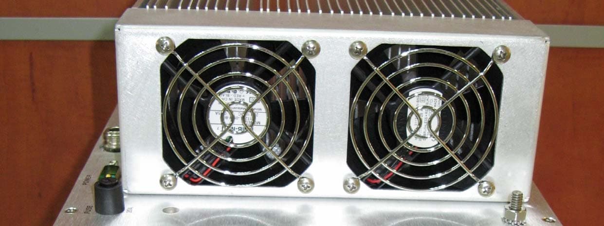
OIWDCSA45047012CH
Mar 17, 2008Digital Channel Selective Amplifier-UHF (DCSA-UHF)
Equipment Class
TNB - Licensed Non-Broadcast Station Transmitter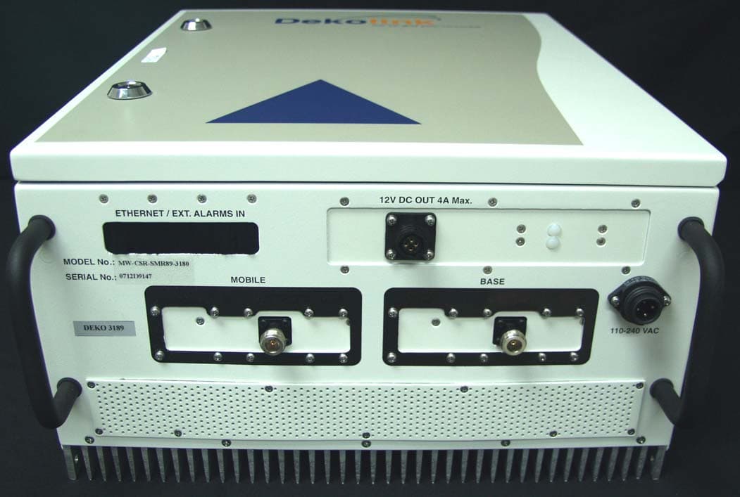
OIWCSRSMR893180
Mar 06, 2008DUAL BAND IDEN REPEATER
Equipment Class
TNB - Licensed Non-Broadcast Station Transmitter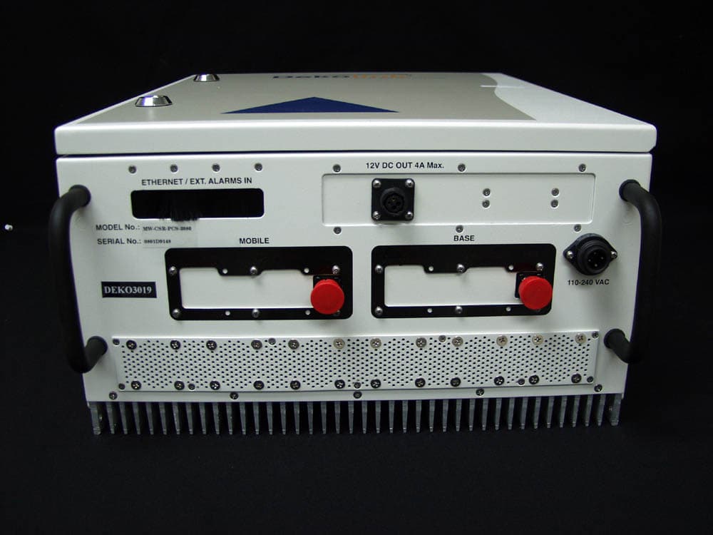
OIWCSRPCS3080
Mar 05, 2008CDMA MIDI REPEATER UNIT 80DB/30DBM WITH CCD
Equipment Class
PCB - PCS Licensed Transmitter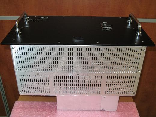
OIWDCSAU47020W90
Mar 03, 2008Digital Channel Selective Amplifier � UHF
Equipment Class
TNB - Licensed Non-Broadcast Station Transmitter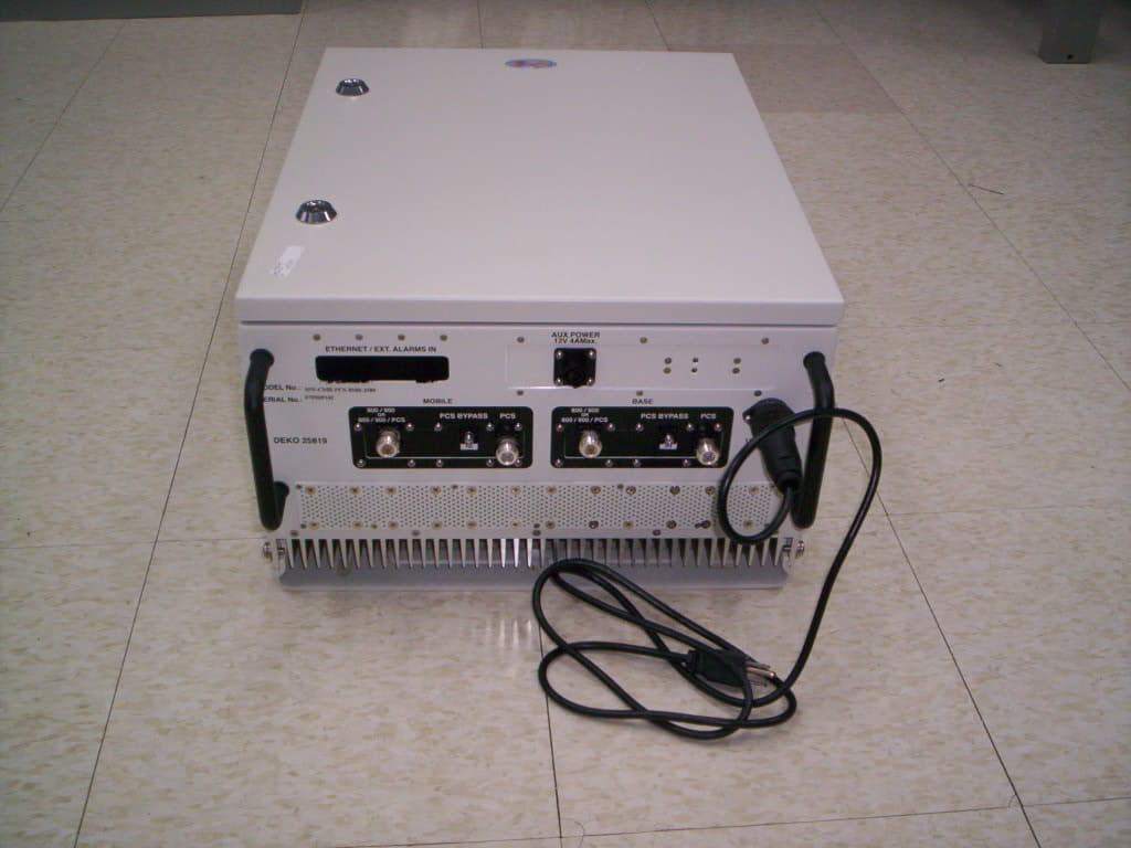
OIWCMRPCSSMR2580
Oct 31, 2007Multi-Band iDEN and WPCS Booster
Equipment Class
PCB - PCS Licensed Transmitter