OIWFBDA800AB50WDMW-FBDA-800AB-50W-DIV
Dekolink Wireless Ltd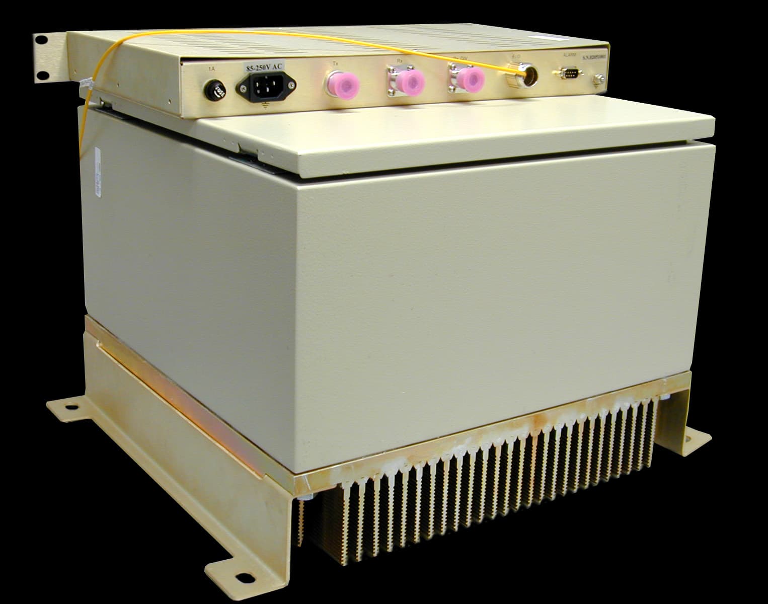
Click to zoom
Application Details
- Equipment Class
- AMP - Amplifier
- Date of Grant
- Aug 26, 2002
- Application Purpose
- Original Equipment
- Date of Application
- Jun 12, 2002
- Equipment Note
- MW-FBDA-800AB-50W-DIV
- Frequency Range
- 869.00000000 - 894.00000000
- Company
- Dekolink Wireless Ltd
- Country
- Israel
Documents & Files
Document Text
Text extracted from the exhibit documents filed with the FCC. Open a document above to read the original.
Users Manual
Dekolink WIRELESS Ltd. 16 Bazel St. Qiryat-Arieh Petah-Tikva, Israel, 49510 Tel- 972-3-9180-180 Fax-972-3-190-9180 e-mail: [email protected] web www.decolink.com INSTALLATION and OPERATION INSTRUCTIONS FOR FiberLink BI-DIRECTIONAL AMPLIFIER WITH DIVERSITY MW-FBDA-800AB-50W-DIV Page 1 of 15 FBDA-800AB-50wDIV-INSTL.doc Dekolink WIRELESS Ltd. 16 Bazel St. Qiryat-Arieh Petah-Tikva, Israel, 49510 Tel- 972-3-9180-180 Fax-972-3-190-9180 e-mail: [email protected] web www.decolink.com TABLE OF CONTENTS PARA No. PARAGRAPH PAGE No. 1. OVERVIEW 3 2. COMPONENT DESCRIPTION 5 2.1 DUPLEXER 5 2.2 UPLINK AMPLIFIER 5 2.3 35 WATT DOWNLINK POWER AMPLIFIER 5 2.4 Fiberoptic transceiver 5 2.5 RFIBER TRANSMITTER 7 2.6 MONITOR UNIT 7 2.7 DISTRIBUTION UNIT 10 2.8 POWER SUPPLY 10 3 ELECTRICAL SPECIFICATIONS 11 3.1 RF SPECIFICATIONS 11 3.2 FBDA ALARM SPECIFICATIONS 12 3.3 MECHANICAL SPECIFICATIONS 12 3.4 ENVIRONMENTAL CONDITIONS 12 4 RF EXPOSURE WARNING 13 LIST OF FIGURES Fig No. Fig. name Page No. 1 FBDA RF BLOCK DIAGRAM 4 2 RFIBER FRONT PANEL 6 3 RFIBER REAR PANEL 6 4 MONITOR OUTLINE 8 5 FIBERLINK ALARM BLOCK DIAGRAM 9 6 FBDA SYSTEM BLOCK DIAGRAM 13 7 MECHANICAL LAYOUT 14 8 MECHANICAL OUTLINE 15 Page 2 of 15 FBDA-800AB-50wDIV-INSTL.doc Dekolink WIRELESS Ltd. 16 Bazel St. Qiryat-Arieh Petah-Tikva, Israel, 49510 Tel- 972-3-9180-180 Fax-972-3-190-9180 e-mail: [email protected] web www.decolink.com 1. OVERVIEW: The FBDA is an interface unit between optical signals carrying RF information, and RF antennas covering a defined user area. The system consists of uplink path and downlink path and an additional uplink path for diversity. The uplink path receives RF signals from the Mobile antenna amplifies them and the Rfiber+ converts them to optical signals. These optical signals are sent to the BTS. The downlink path receives optical signals from the BTS to the Rfiber+, converts them to RF signals and amplifies these signals using a high power amplifier. The Mobile antenna transmits these RF signals. A duplexing filter separates the frequencies of uplink path from the downlink path enabling the use of the same antenna for receiving and transmitting. The FBDA provides about 46 dB RF gain in both directions. Both optical signals for Uplink and Downlink are carried on a single fiber using WDM. Downlink gain can be adjusted using a trim pot on the Rfiber+ front panel for proper output power. Uplink gain can be adjusted by 16 dB continuous trim pot. The downlink path uses a 50 Watt power amplifier while the uplink uses an AGC amplifier to drive the uplink F/O transmitter. The AGC is set to 0 dBm, which is the max power required by the F/O transmitter. For diversity reasons there is an additional Uplink path consisting of Cavity band pass filter, AGC amplifier, and Fiber optic transmitter. The optical signal of this path is transferred via an additional fiber to the base station. Page 3 of 15 FBDA-800AB-50wDIV-INSTL.doc Dekolink WIRELESS Ltd. 16 Bazel St. Qiryat-Arieh Petah-Tikva, Israel, 49510 Tel- 972-3-9180-180 Fax-972-3-190-9180 e-mail: [email protected] web www.decolink.com Fig. 1 : FBDA RF BLOCK DIAGRAM Optical Fiber Downlink /Uplink Fiberoptic Transmitter Fiberoptic Receiver Duplexer RX Step Attenuator TX UP LINK AMP Variable Attenuator Down link Power Amplifier AGC Uplink (diversity) Fiberoptic Transmitter UP LINK AMP Variable Attenuator AGC Filter Rx1 WDM Optical Fiber TO BTS Page 4 of 15 FBDA-800AB-50wDIV-INSTL.doc Dekolink WIRELESS Ltd. 16 Bazel St. Qiryat-Arieh Petah-Tikva, Israel, 49510 Tel- 972-3-9180-180 Fax-972-3-190-9180 e-mail: [email protected] web www.decolink.com 2. COMPONENTS DESCRIPTION: 2.1 DUPLEXER(x2) The duplexer serves to frequency separate uplink signals from downlink signals. The duplexer has sharp out of band attenuation for better isolation between the receiving and transmitting paths and for better rejection of interfering signal in the air. In the Diversity path only the Rx part of the duplexer is used. 2.2 UPLINK AMPLIFIER(both Rx pathes) The uplink amplifier is a low noise, 45dB gain unit. The amplifier contains AGC control circuitry. When a high power signal is received the automatic level control detects it and reduces the gain so that the output power of the amplifier is constant. The AGC function limits the signal at the Fiberoptic transmitter input when high power signals are received while keeping high gain when low power signals are received. The LED on the amplifier illuminates when the power output of the amplifier exceeds the AGC power set limit (when the AGC is either ON or OFF). The Switch on the RF amplifier enables the AGC function. If the AGC is disabled then the amplifier gives maximum gain for any input. The AGC level is factory set to 0 dBm and AGC is set to ON, to prevent high power damage at the Rfiber+ input. 2.3 50 WATT DOWNLINK POWER AMPLIFIER This is the downlink power amplifier. It can drive 40 dBm composite power to the MOBILE antenna. A thermostat attatched to this amplifier turns on TEMP alarm when the temperature exceeds 80° C. 2.4 Fiberoptic to RF transceiver The RFiber+ TM product is a transceiver that includes a transmitter and receiver unit. The transmitter converts the RF signals into light wave signals, which are then sent over fiberoptic cables. The receiver converts light wave signals back to RF The model in use is a wide band product in the 0.08-1 GHz frequency range and it includes a WDM module to enable use of one fiber for Tx and Rx signals. Page 5 of 15 FBDA-800AB-50wDIV-INSTL.doc Dekolink WIRELESS Ltd. 16 Bazel St. Qiryat-Arieh Petah-Tikva, Israel, 49510 Tel- 972-3-9180-180 Fax-972-3-190-9180 e-mail: [email protected] web www.decolink.com The RFiber+ TM main features are: 1. Protocol transparency; i.e. any standard can be faithfully transmitted. 2. An optional serial port (RS232) is installed into each unit. This port allows data communication over the same fiberoptic cable. 3. Max. input RF power for normal operation – …
Text truncated - open the document above for the full version.
Users Manual
Dekolink WIRELESS Ltd. 16 Bazel St. Qiryat-Arieh Petah-Tikva, Israel, 49510 Tel- 972-3-9180-180 Fax-972-3-190-9180 e-mail: [email protected] web www.decolink.com INSTALLATION AND OPERATING INSTRUCTIONS FOR CELLULAR A+B Fiber-optic REPEATER SYSTEM 50W WITH DIVERSITY & FiberopticBase Interface Unit Page 1 of 1 FO-800AB-50W SYS.doc Dekolink WIRELESS Ltd. 16 Bazel St. Qiryat-Arieh Petah-Tikva, Israel, 49510 Tel- 972-3-9180-180 Fax-972-3-190-9180 e-mail: [email protected] web www.decolink.com TABLE OF CONTENTS PARA No. PARAGRAPH PAGE No. 1. OVERVIEW 3 1.1 FBIU 3 1.2 FBDA 4 2. SUBSYSTEM DESCRIPTION 5 2.1 FBDA 5 2.2 FBIU 5 2.2.1 FIBEROPTIC TRANSCEIVER 5 2.2.2 DUPLEXER 5 2.2.3 ATTENUATOR 5 3 SYSTEM SPECIFICATIONS 7 3.1 RF SPECIFICATIONS 7 3.2 FBDA ALARM SPECIFICATIONS 8 3.3 MECHANICAL SPECIFICATIONS 8 3.4 ENVIRONMENTAL CONDITIONS 8 4 INSTALLATION PROCEDURE 9 4.1 FIBER OPTIC LINK ASSEMBLY 9 4.2 DOWNLINK CALLIBRATION 9 4.3 UPLINK CALLIBRATION 9 4.4 SYSTEM ASSEMBLY 10 LIST OF FIGURES Fig No. Fig. name Page No. 1 FIBEROPTIC REPEATER SYSTEM BLOCK DIAGRAM 4 2 FBIU RF BLOCK DIAGRAM 6 3 FBIU MECHANICAL LAYOUT 11 Page 2 of 2 FO-800AB-50W SYS.doc Dekolink WIRELESS Ltd. 16 Bazel St. Qiryat-Arieh Petah-Tikva, Israel, 49510 Tel- 972-3-9180-180 Fax-972-3-190-9180 e-mail: [email protected] web www.decolink.com 1. OVERVIEW: The Fiber optic repeater system is an excellent solution for BTS coverage extension by means of Fiber optic link and remote high power RF head. The system consists of two conversion boxes; - FBIU (Fiberoptic Base Interface Unit) - FBDA (Fiber optic Bi Directional Amplifier) Two fibers, one for main path, uplink and downlink direction and one in diversity uplink direction connect the FBIU to the FBDA. Using fiberoptic cable allows long distance transmission, up to 20 Km. 1.1 FBIU The FBIU is installed near the BTS and is connected to the BTS by RF cables. A Fiberoptic transceiver converts the Downlink RF signals to optical signals and the uplink optical signal to RF. A high power attenuator is used as power adjustment between BTS Tx power and Fiberoptic transceiver requirements. A separate attenuator is used for Rx direction. The Diversity path is connected through Fiberoptic receiver and fixed attenuator to the Diversity receiver. Page 3 of 3 FO-800AB-50W SYS.doc Dekolink WIRELESS Ltd. 16 Bazel St. Qiryat-Arieh Petah-Tikva, Israel, 49510 Tel- 972-3-9180-180 Fax-972-3-190-9180 e-mail: [email protected] web www.decolink.com 1.2 FBDA The FBDA is installed near the area to be covered and is connected to the mobile antenna. A Fiberoptic transceiver converts the Downlink optical signals to RF signals and the uplink RF signals to optical signals. A duplexer in the FBDA separates the uplink and downlink signals thus enabling the use of the same antenna for receiving and transmitting. The duplexer has sharp out of band attenuation for better isolation between the receiving and transmitting paths and for reduction of out of band interfering signals. A high power amplifier in the downlink path produces high RF power to the antenna. A LNA (low noise amplifier) is used to drive the uplink signals from the antenna to the Fiberoptic transceiver input to maintain reasonable NF (noise figure) in the uplink path. The FBDA contains a monitoring unit to monitor the operation of the active elements inside the FBDA. Whenever a fault occurs an ALARM signal is sent to the FBIU. For diversity applications the uplink path is duplicated using separate antenna, filter, LNA and Fiberoptic transmitter. Fig. 1 : Fiber-optic REPEATER SYSTEM BLOCK DIAGRAM Mobile ANT. BTS High pwr ATTN. Tx Rx F/O+ WDM RF IN RF Out optical in/out optical in F/O+ WDM optical in/out optical Out FBDA RF section BASE SITE FIBEROPTIC CABLE RUN UP TO 20Km ATTN. (MAX. 0dBm) F/O F/O RF Out ATTN. Rx1 Page 4 of 4 FO-800AB-50W SYS.doc Dekolink WIRELESS Ltd. 16 Bazel St. Qiryat-Arieh Petah-Tikva, Israel, 49510 Tel- 972-3-9180-180 Fax-972-3-190-9180 e-mail: [email protected] web www.decolink.com 2. SUBSYSTEM DESCRIPTION: 2.1 FBDA Please refer to installation and operation instructions for FBDA-800AB-50W-DIV 2.2 FBIU The FBIU is the BTS interface of the system. It includes Fiberoptic transceiver, duplexer and attenuator for main uplink and downlink , uplink diversity Fiberoptic transmitter receiver and attenuator, and power supply. 2.2.1Fiberoptic transceiver The Fiberoptic transceiver converts the signal form RF to optical in the downlink direction and from optical signal to RF in the uplink direction. 2.2.2 DUPLEXER The duplexer separates the uplink and downlink signals to anable one RF cable connection to the BTS. In case of separate connections for Rx and Tx , the duplexer is not required. 2.2.3 ATTENUATOR Assuming that the output power of BTS is +30dBm, a 30 dB high power external attenuator is required. In practice, more attenuation can be added Page 5 of 5 FO-800AB-50W SYS.doc Dekolink WIRELESS Ltd. 16 Bazel St. Qiryat-Arieh Petah-Tikva, Israel, 49510 Tel- 972-3-9180-180 Fax-972-3-190-9180 e-mail: [email protected] web www.decolink.com for different system setting. In case of separate connections for Rx and Tx , separate attenuators for Rx and Tx should be used. TO BTS FIG 2: FBIU RF BLOCK DIAGRAM (without duplexer) High pwr ATTN. F/O+ WDM RF IN RF Out optical in/out optical in ATTN. (MAX. 0dBm) F/O RF Out ATTN. VAR. ATTN. Page 6 of 6 FO-800AB-50W SYS.doc Dekolink WIRELESS Ltd. 16 Bazel St. Qiryat-Arieh Petah-Tikva, Israel, 49510 Tel- 972-3-9180-180 Fax-972-3-190-9180 e-mail: [email protected] web www.decolink.com 3 . SYSTEM SPECIFICATIONS: 3.1 RF SPECIFICATIONS (optical loss adjusted to 0dBm, all attenuators 30 dB) Uplink (RX, DIV) Downlink (TX) Frequency Range 824-849 MHz 869-894 MHz Passband Gain @ min attenuation 16 dB Nom. 10dB Nom. Passband Ripple ± 1.0 dB typical Manual Attenuation Range 0 to 16 db cont. (FBDA side) 0-10 dB in 1dB steps (FBIU side) Noise Figure @+25 ° C (optical loss less than 3 dB) 6.0 dB m…
Text truncated - open the document above for the full version.
Users Manual
Dekolink WIRELESS Ltd. 16 Bazel St. Qiryat-Arieh Petah-Tikva, Israel, 49510 Tel- 972-3-9180-180 Fax-972-3-190-9180 e-mail: [email protected] web www.decolink.com INSTALLATION and OPERATION INSTRUCTIONS FOR FiberLink BI-DIRECTIONAL AMPLIFIER WITH DIVERSITY MW-FBDA-800AB-50W-DIV Page 1 of 15 FBDA-800AB-50wDIV-INSTL1.doc Dekolink WIRELESS Ltd. 16 Bazel St. Qiryat-Arieh Petah-Tikva, Israel, 49510 Tel- 972-3-9180-180 Fax-972-3-190-9180 e-mail: [email protected] web www.decolink.com TABLE OF CONTENTS PARA No. PARAGRAPH PAGE No. 1. OVERVIEW 3 2. COMPONENT DESCRIPTION 5 2.1 DUPLEXER 5 2.2 UPLINK AMPLIFIER 5 2.3 35 WATT DOWNLINK POWER AMPLIFIER 5 2.4 Fiberoptic transceiver 5 2.5 RFIBER TRANSMITTER 7 2.6 MONITOR UNIT 7 2.7 DISTRIBUTION UNIT 10 2.8 POWER SUPPLY 10 3 ELECTRICAL SPECIFICATIONS 11 3.1 RF SPECIFICATIONS 11 3.2 FBDA ALARM SPECIFICATIONS 12 3.3 MECHANICAL SPECIFICATIONS 12 3.4 ENVIRONMENTAL CONDITIONS 12 4 RF EXPOSURE WARNING 13 LIST OF FIGURES Fig No. Fig. name Page No. 1 FBDA RF BLOCK DIAGRAM 4 2 RFIBER FRONT PANEL 6 3 RFIBER REAR PANEL 6 4 MONITOR OUTLINE 8 5 FIBERLINK ALARM BLOCK DIAGRAM 9 6 FBDA SYSTEM BLOCK DIAGRAM 13 7 MECHANICAL LAYOUT 14 8 MECHANICAL OUTLINE 15 Page 2 of 15 FBDA-800AB-50wDIV-INSTL1.doc Dekolink WIRELESS Ltd. 16 Bazel St. Qiryat-Arieh Petah-Tikva, Israel, 49510 Tel- 972-3-9180-180 Fax-972-3-190-9180 e-mail: [email protected] web www.decolink.com 1. OVERVIEW: The FBDA is an interface unit between optical signals carrying RF information, and RF antennas covering a defined user area. The system consists of uplink path and downlink path and an additional uplink path for diversity. The uplink path receives RF signals from the Mobile antenna amplifies them and the Rfiber+ converts them to optical signals. These optical signals are sent to the BTS. The downlink path receives optical signals from the BTS to the Rfiber+, converts them to RF signals and amplifies these signals using a high power amplifier. The Mobile antenna transmits these RF signals. A duplexing filter separates the frequencies of uplink path from the downlink path enabling the use of the same antenna for receiving and transmitting. The FBDA provides about 46 dB RF gain in both directions. Both optical signals for Uplink and Downlink are carried on a single fiber using WDM. Downlink gain can be adjusted using a trim pot on the Rfiber+ front panel for proper output power. Uplink gain can be adjusted by 16 dB continuous trim pot. The downlink path uses a 50 Watt power amplifier while the uplink uses an AGC amplifier to drive the uplink F/O transmitter. The AGC is set to 0 dBm, which is the max power required by the F/O transmitter. For diversity reasons there is an additional Uplink path consisting of Cavity band pass filter, AGC amplifier, and Fiber optic transmitter. The optical signal of this path is transferred via an additional fiber to the base station. Page 3 of 15 FBDA-800AB-50wDIV-INSTL1.doc Dekolink WIRELESS Ltd. 16 Bazel St. Qiryat-Arieh Petah-Tikva, Israel, 49510 Tel- 972-3-9180-180 Fax-972-3-190-9180 e-mail: [email protected] web www.decolink.com Fig. 1 : FBDA RF BLOCK DIAGRAM Optical Fiber Downlink /Uplink Fiberoptic Transmitter Fiberoptic Receiver Duplexer RX Step Attenuator TX UP LINK AMP Variable Attenuator Down link Power Amplifier AGC Uplink (diversity) Fiberoptic Transmitter UP LINK AMP Variable Attenuator AGC Filter Rx1 WDM Optical Fiber TO BTS Page 4 of 15 FBDA-800AB-50wDIV-INSTL1.doc Dekolink WIRELESS Ltd. 16 Bazel St. Qiryat-Arieh Petah-Tikva, Israel, 49510 Tel- 972-3-9180-180 Fax-972-3-190-9180 e-mail: [email protected] web www.decolink.com 2. COMPONENTS DESCRIPTION: 2.1 DUPLEXER(x2) The duplexer serves to frequency separate uplink signals from downlink signals. The duplexer has sharp out of band attenuation for better isolation between the receiving and transmitting paths and for better rejection of interfering signal in the air. In the Diversity path only the Rx part of the duplexer is used. 2.2 UPLINK AMPLIFIER(both Rx pathes) The uplink amplifier is a low noise, 45dB gain unit. The amplifier contains AGC control circuitry. When a high power signal is received the automatic level control detects it and reduces the gain so that the output power of the amplifier is constant. The AGC function limits the signal at the Fiberoptic transmitter input when high power signals are received while keeping high gain when low power signals are received. The LED on the amplifier illuminates when the power output of the amplifier exceeds the AGC power set limit (when the AGC is either ON or OFF). The Switch on the RF amplifier enables the AGC function. If the AGC is disabled then the amplifier gives maximum gain for any input. The AGC level is factory set to 0 dBm and AGC is set to ON, to prevent high power damage at the Rfiber+ input. 2.3 50 WATT DOWNLINK POWER AMPLIFIER This is the downlink power amplifier. It can drive 40 dBm composite power to the MOBILE antenna. A thermostat attatched to this amplifier turns on TEMP alarm when the temperature exceeds 80° C. 2.4 Fiberoptic to RF transceiver The RFiber+ TM product is a transceiver that includes a transmitter and receiver unit. The transmitter converts the RF signals into light wave signals, which are then sent over fiberoptic cables. The receiver converts light wave signals back to RF The model in use is a wide band product in the 0.08-1 GHz frequency range and it includes a WDM module to enable use of one fiber for Tx and Rx signals. Page 5 of 15 FBDA-800AB-50wDIV-INSTL1.doc Dekolink WIRELESS Ltd. 16 Bazel St. Qiryat-Arieh Petah-Tikva, Israel, 49510 Tel- 972-3-9180-180 Fax-972-3-190-9180 e-mail: [email protected] web www.decolink.com The RFiber+ TM main features are: 1. Protocol transparency; i.e. any standard can be faithfully transmitted. 2. An optional serial port (RS232) is installed into each unit. This port allows data communication over the same fiberoptic cable. 3. Max. input RF power for normal operati…
Text truncated - open the document above for the full version.
Block Diagram
Dekolink WIRELESS Ltd. 16 Bazel St. Qiryat-Arieh Petah-Tikva, Israel, 49510 Tel- 972-3-9180-180 Fax-972-3-190-9180 e-mail: [email protected] web www.decolink.com Fig. 1 : FBDA RF BLOCK DIAGRAM Optical Fiber Downlink /Uplink Fiberoptic Transmitter Fiberoptic Receiver Duplexer RX Step Attenuator TX UP LINK AMP Variable Attenuator Down link Power Amplifier AGC Uplink (diversity) Fiberoptic Transmitter UP LINK AMP Variable Attenuator AGC Filter Rx1 WDM Optical Fiber TO BTS Page 4 of 15 FBDA-800AB-50wDIV-INSTL.doc
ID Label/Location Info
Dekolink WIRELESS Ltd. 16 Bazel St. Qiryat-Arieh Petah-Tikva, Israel, 49510 Tel- 972-3-9180-180 Fax-972-3-190-9180 e-mail: [email protected] web www.decolink.com FCC ID: OIWFBDA800AB50WD LABEL FORMAT Page 1 of 1 FCC ID FBDA 800AB.doc
ID Label/Location Info
Dekolink WIRELESS Ltd. 16 Bazel St. Qiryat-Arieh Petah-Tikva, Israel, 49510 Tel- 972-3-9180-180 Fax-972-3-190-9180 e-mail: [email protected] web www.decolink.com FCC ID: OIWFBDA800AB50WD LABEL FORMAT Page 1 of 1 FCC ID FBDA 800AB.doc
ID Label/Location Info
Dekolink WIRELESS Ltd. 16 Bazel St. Qiryat-Arieh Petah-Tikva, Israel, 49510 Tel- 972-3-9180-180 Fax-972-3-190-9180 e-mail: [email protected] web www.decolink.com
Operational Description
Dekolink WIRELESS Ltd. 16 Bazel St. Qiryat-Arieh Petah-Tikva, Israel, 49510 Tel- 972-3-9180-180 Fax-972-3-190-9180 e-mail: [email protected] web www.decolink.com Page 1 of 10 249560 SPECIFICATIONS FOR FiberLink BI-DIRECTIONAL AMPLIFIER WITH DIVERSITY MW-FBDA-800AB-50W-DIV Dekolink WIRELESS Ltd. 16 Bazel St. Qiryat-Arieh Petah-Tikva, Israel, 49510 Tel- 972-3-9180-180 Fax-972-3-190-9180 e-mail: [email protected] web www.decolink.com Page 2 of 10 249560 TABLE OF CONTENTS PARA No.PARAGRAPHPAGE No. 1.OVERVIEW3 2.COMPONENT DESCRIPTION5 2.1DUPLEXER5 2.2UPLINK AMPLIFIER5 2.335 WATT DOWNLINK POWER AMPLIFIER5 2.4 Fiberoptic transceiver 5 2. 5 M O NI TO R UNI T6 2.6 POWER SUPPLY6 3 ELECTRICAL SPECIFICATIONS7 3.1 RF SPECIFICATIONS7 3.2FBDA ALARM SPECIFICATIONS8 3.3 MECHANICAL SPECIFICATIONS8 3.4 ENVIRONMENTAL CONDITIONS8 LIST OF FIGURES Fig No.Fig. namePage No. 1FBDA RF BLOCK DIAGRAM 4 2FBDA SYSTEM BLOCK DIAGRAM 9 3 MECHANICAL OUTLINE10 Dekolink WIRELESS Ltd. 16 Bazel St. Qiryat-Arieh Petah-Tikva, Israel, 49510 Tel- 972-3-9180-180 Fax-972-3-190-9180 e-mail: [email protected] web www.decolink.com Page 3 of 10 249560 1. OVERVIEW: The FBDA is an interface unit between optical signals carrying RF information, and a RF antenna covering a defined user area. The system consists of uplink path and downlink path. The uplink path receives RF signals from the Mobile antenna and amplifies them and converts them to optical signals. These optical signals are sent to the BTS. The downlink path receives optical signals from the BTS, converts them to RF signals and amplifies these signals using a high power amplifier. The Mobile antenna transmits these RF signals. A duplexing filter separates the frequencies of uplink path from the downlink path enabling the use of the same antenna for receiving and transmitting. The FBDA provides about 46 dB RF gain in both directions. Both optical signals for Uplink and Downlink are carried on a single fiber using WDM. Downlink gain can be adjusted on the fiber optic unit to set the FBDA downlink RF power. Uplink gain can be adjusted by 16 dB continuous trim pot., however max gain is usually optimum. The downlink path uses a 50 Watt power amplifier while the uplink uses an AGC amplifier to drive the uplink F/O transmitter. The AGC level is set to 0 dBm, which is the max power required by the F/O transmitter. For diversity there is an additional Uplink path consisting of Cavity band pass filter, AGC amplifier, and Fiber optic transmitter. The optical signal of this path is transferred via an additional fiber to the base station. Dekolink WIRELESS Ltd. 16 Bazel St. Qiryat-Arieh Petah-Tikva, Israel, 49510 Tel- 972-3-9180-180 Fax-972-3-190-9180 e-mail: [email protected] web www.decolink.com Page 4 of 10 249560 Fig. 1 : FBDA RF BLOCK DIAGRAM Optical Fiber Downlink / Uplink Fiberoptic Transmitter Fiberoptic Receiver Duplexer RX Step Attenuator TX UP LINK AMP Variable Attenuator Down link Power Amplifier AGC Uplink (diversity) Fiberoptic Transmitter UP LINK AMP Variable Attenuator AGC Filter Rx1 WDM Optical Fiber TO BTS Dekolink WIRELESS Ltd. 16 Bazel St. Qiryat-Arieh Petah-Tikva, Israel, 49510 Tel- 972-3-9180-180 Fax-972-3-190-9180 e-mail: [email protected] web www.decolink.com Page 5 of 10 249560 2. COMPONENTS DESCRIPTION: 2.1 DUPLEXER The duplexer serves to frequency separate uplink signals from downlink signals. The duplexer has sharp out of band attenuation for better isolation between the receiving and transmitting paths 2.2 UPLINK AMPLIFIER (both Rx pathes) The uplink amplifier contains AGC control circuitry. The AGC function helps to limit the signal at the F/O when high power signals are received while keeping high gain when receiving low power signals. The LED on the amplifier illuminates when the power output of the amplifier is within the set limit (when the AGC is either On or OFF). The Switch on the RF amplifier enables the AGC function. If the AGC is disabled then the amplifier gives maximum gain at all times. AGC switch should be on to prevent high power signals damage the fiber optic unit . 2.3 50 WATT DOWNLINK POWER AMPLIFIER This is the downlink power amplifier. It is attached to high power dissipation heat sink. A thermostat attached to this amplifier turns off the FBDA power supply when the temperature exceeds 80° C. 2.4 Fiberoptic to RF transceiver The Fiberoptic transceiver includes a transmitter and receiver unit. The transmitter converts the RF signals into optical signals, which are then sent over optical fiber. The receiver converts light wave signals back to RF. Using optical fiber cable allows long distance transmission, up to 20 Km. Dekolink WIRELESS Ltd. 16 Bazel St. Qiryat-Arieh Petah-Tikva, Israel, 49510 Tel- 972-3-9180-180 Fax-972-3-190-9180 e-mail: [email protected] web www.decolink.com Page 6 of 10 249560 2.5 MONITOR UNIT The FBDA monitor performs the following functions: a) Monitors the DC supply voltage of the FBDA. The fault LED illuminates when the voltage is beyond the specified limits. b) Monitors the current to each active element and the two fans at the FBDA panel. (The fans for the high power downlink amplifiers are connected directly to the amplifier). If the current is below or above the specified limits then a LED illuminates. c) Monitor the optical receive signal using alarm output of the optical transceiver. d) Provides automatic alarm function. A relay in the monitor box opens whenever any fault occurs or when the power is removed from the FBDA. The relay arms are normally open and close only when no fault occurs. e) Provides self test for the alarm functions. The pushbutton switch on the Monitor unit turns on all the alarm LEDs and opens the relay arms. f) Send summarized alarm signal to the base station via the F/O data port. 2.6 POWER SUPPLY This is a high efficiency dual switching power supply providing +28 VDC at over 6 Amp for the power amp and +15VDC for other elements. Dekolink WIRELESS Ltd. 16…
Text truncated - open the document above for the full version.
Parts List/Tune Up Info
Dekolink WIRELESS Ltd. 16 Bazel St. Qiryat-Arieh Petah-Tikva, Israel, 49510 Tel- 972-3-9180-180 Fax-972-3-190-9180 e-mail: [email protected] web www.decolink.com 28 May 02 FCC ID: OIWFBDA800AB50WD PARTS LIST Part No Description Quantity 1543003083 250W Single&Multi Output Power Supply 1.00 1510992641 AMP RF 800-960MHZ 50W 1.00 300LA12000 CELL F/O DRIVER AGC-45dB 2.00 300LA36000 STEP ATTENUATOR 1.00 30WRA90001 SM141-25N-11SMA-17cm 1.00 30WRA90002 SM141-11SMA(x2)-30cm 1.00 30WRA90003 SM141-11SMA(x2)-20cm 1.00 30WRA90004 SM141-11SMA(x2)-53cm 1.00 30WRA90005 SM141-11SMA(x2)-9cm 1.00 30WRA90006 SM141-11SMA(x2)-25cm 1.00 30WRA90007 SM141-25N-11SMA-21cm 1.00 30WRA90008 SM141-11SMA(x2)-25cm 1.00 30WRA90009 SM141-11SMA(x2)-34cm 1.00 1519941861 RFIBER TRANSM 100-1000MHZ WIDE BND 1310nm 1.00 1519941844 RFIBER+(Tx+Rx) 60-1000MHZ RS232 D.MODEM 1.00 1513200091 Diplexer Cell A+B for BDA 10w 2.00 300RA90150 HEAT-SINK REWORK 1.00 300RA90050 CHASSIS 1.00 300JA14000 BDA MONITOR 1.00 300NA54000 CONNECTION BOX ASSY 1.00 1511202821 LOAD DC-18MHZ 50 OHM 1.00 1501001321 FAN 12V DC 0-0.08A 39dbA SQ92MMX25MM 1.00 Page 1 of 1 PART LIST FBDA 800AB 50WDIV.doc
RF Exposure Info
Maximum Permissible Exposure (MPE) Compliance Statement, FCC Radio Frequency Exposure Limit 1.1310 Health Canada Safety Code 6 MW FBDA-800AB-50W-DIV Fiber Optic Repeater System The MW FBDA-800AB-50W-DIV Fiber Optic Repeater System has been tested and the performance characterized in accordance with the MPE requirements of FCC 47 CFR and RSS 102. At the maximum operating frequency of 894MHz the MPE limit for the General Population/Uncontrolled Exposure is 0.6mW/cm 2 (f/1500mW/cm 2 ). This device complies with this limit at the following line of sight distances from the antenna element: MW FBDA-800AB-50W-DIV : 51.5cm The analysis is provided below. Power Density (S) = EIRP/(4πR 2 ), Therefore, R≥√EIRP/S x 4π Using this calculation: Maximum Antenna Gain = 3dBi Maximum output power = 40dBm S = 0.6 mW/cm 2 EIRP = 43dBm or 20W(max. worst case) Theref ore, R= 51.5cm This minimum safe distance for the general population of 51.5cm shall be stated in the installation & operators instruction manual under the RF Safety Exposure Warning Statement. Analysis provided by, Glen Westwell, Nemko Canada Inc. for Dekolink Wireless Ltd.
Schematics
Dekolink WIRELESS Ltd. 16 Bazel St. Qiryat-Arieh Petah-Tikva, Israel, 49510 Tel- 972-3-9180-180 Fax-972-3-190-9180 e-mail: [email protected] web www.decolink.com FCC ID: OIWFBDA800AB50WD OpticalFiber Uplink Div. TO MOBILE TO BASE Fiberoptic Transmitter Fiberoptic Receiver Duplexer RX VariableAttenuator TX Power Amplifier Power Monitor PA AGC FBDA MONITOR CURRENT SENSORS OP TIC A L A L A R M SU MM E R I Z E D AL A R M O U T FAN DUAL POWER SUPPLY +13.5 V AC CORD +V IN FBDA-800AB-50W-DIV ELELCTRICAL SCHEMATICS +28 V Power Monitor PA AGC FILTER Fiberoptic Transmitter Uplink/Downlink Page 1 of 1 FBDA-800AB-50W-DIV schematic.doc
Test Report
Master: Generic FCC Date: October 16, 2001 Test Report:2W06066 Applicant:Dekolink Wireless LTD. 16 Bazel St. Qiryat-Arieh Petah-Tikva, 49510 Israel Equipment Under Test:MW FBDA-800AB-50W-DIV (EUT)Fiber Optic Repeater System FCC ID:OIWFBDA800AB50WD In Accordance With:FCC Part 22, Subpart H Tested By:Nemko Canada Inc. 303 River Road, R.R. 5 Ottawa, Ontario K1V 1H2 Authorized By:Glen Westwell, Wireless Technologist Date:12 June 2002 Total Number of Pages:23 Nemko Canada Inc. PROJECT NO.:2W06066 EQUIPMENT: MW FBDA-800AB-50W-DIV Page 2 of 23 Table of Contents Section 1. Summary of Test Results......................................................................................3 Section 2. General Equipment Specification........................................................................5 Section 3. RF Power Output..................................................................................................6 Section 4. Occupied Bandwidth............................................................................................8 Section 5. Spurious Emissions at Antenna Terminals........................................................12 Section 6. Field Strength of Spurious Emissions................................................................17 Section 7.Frequency Stability..............................................................................................20 Section 8.Block Diagrams....................................................................................................21 Section 9.Test Equipment List............................................................................................23 Nemko Canada Inc. PROJECT NO.:2W06066 EQUIPMENT: MW FBDA-800AB-50W-DIV Page 3 of 23 Section 1.Summary of Test Results General All measurements are traceable to national standards. These tests were conducted on a sample of the equipment for the purpose of demonstrating co…
Text truncated - open the document above for the full version.
Contact Information
Applicant
Yaron Moas
Technical Contact
Nemko Canada Inc.Ruby Dulmage
[email protected]613-737-9680
303 River Road, R.R. 5 · Ottawa, Ontario · Canada
Non-Technical Contact
Nemko Canada Inc.Ruby Dulmage
[email protected]613-737-9680
Test Firm
Nemko Canada Inc.Stuart Beck
Technical Specifications
| # | Rule Parts | Frequency Range | Power Output | Emission |
|---|---|---|---|---|
| 3 | 22H | 869 MHz - 894 MHz | 8.5 W | F8W |
Other Applications from Dekolink Wireless Ltd
OIWDCSA45047012CH
Mar 17, 2008Digital Channel Selective Amplifier-UHF (DCSA-UHF)
Equipment Class
TNB - Licensed Non-Broadcast Station Transmitter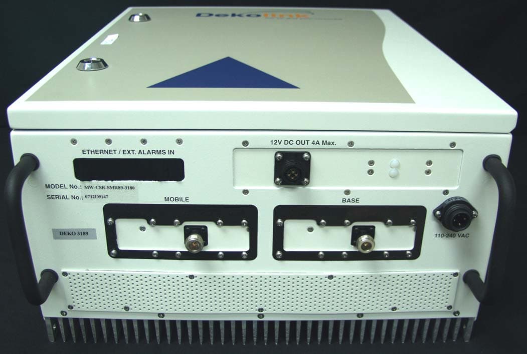
OIWCSRSMR893180
Mar 06, 2008DUAL BAND IDEN REPEATER
Equipment Class
TNB - Licensed Non-Broadcast Station Transmitter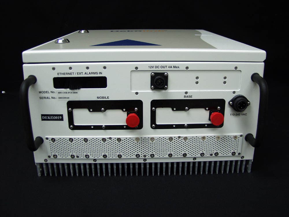
OIWCSRPCS3080
Mar 05, 2008CDMA MIDI REPEATER UNIT 80DB/30DBM WITH CCD
Equipment Class
PCB - PCS Licensed Transmitter
OIWDCSAU47020W90
Mar 03, 2008Digital Channel Selective Amplifier � UHF
Equipment Class
TNB - Licensed Non-Broadcast Station Transmitter
OIWCMRPCSSMR2580
Oct 31, 2007Multi-Band iDEN and WPCS Booster
Equipment Class
PCB - PCS Licensed Transmitter