OJ7901GMR0903FRS/GMRS UHF Transceiver
Victory Concept Industries Ltd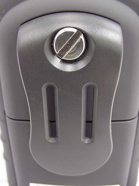
Click to zoom
Application Details
- Equipment Class
- FRF - Part 95 Family Radio Face Held Transmitter
- Date of Grant
- Nov 04, 2003
- Application Purpose
- Original Equipment
- Date of Application
- Nov 04, 2003
- Equipment Note
- FRS/GMRS UHF Transceiver
- Frequency Range
- 467.56250000 - 467.71250000
- Country
- Hong Kong
Documents & Files
Document Text
Text extracted from the exhibit documents filed with the FCC. Open a document above to read the original.
Users Manual
901 GMRS User Manual V 1.0 Date : 2003/9/19 Page 1 901GMRS User Manual Prelim OPERATION BUTTONS : z POWER z PTT z UP z DOWN\ z MODE z MONITOR z SCAN/LOCK z CALL Features and Operating Procedures Turn the Radio ON/OFF 1. Press and release [POWER]. The display will appear (all segments will turn on for 1 second) 2. The LCD display will show the current channel number. 3. To turn the radio off, press and hold [POWER] for 1 second until the display clears. Adjust the Volume 1. In normal operating mode, press the [UP] or [DOWN] buttons to raise or lower the radio’s volume. 2. The radio will beep to indicate the volume level is changed. Key Tones 1. The Key tones (press any key, except the [PTT] and [MODE] button) on the radio are at fixed level and are not affected by changing the radio’s volume 2. The [PTT] and [MODE] button does not have key tone. 3. If speaker is enabled, there will be no key tone for [UP] or [DOWN] keys. Change the Channel 1. From the normal operating mode, press [MODE] button once to enter the channel selection menu. The CHAN indicator will begin to flash and the radio’s current Channel will be shown. 2. Use the [UP] or [DOWN] buttons to select a new channel (1-22) while the CHAN indicator is flashing. 3. The radio will return to the normal operating mode after 10 seconds or when you press the [PTT] button or press [MODE] several times back to normal operation mode. Change the CTCSS Tone 1 From the normal operating mode, press [MODE] 2 times to enter the CTCSS selection menu. The CTCSS indicator will begin to flash and the radio’s current CTCSS will be shown. 2 Press the [UP] or [DOWN] button to select a new code while the CODE icon is flashing. (Codes 1-38 are selectable. If you don’t want this code, set it to ‘--’). 3 The radio will return to the normal operating mode after 10 seconds or when you press the [PTT] button or press [MODE] several times back to normal operation mode. 901 GMRS User Manual V 1.0 Date : 2003/9/19 Page 2 To change and hear a Call-Ring tone: 1. From the normal operating mode, press [MODE] 3 times to enter the Call-Ring selection menu. The CALL indicator will appear and the large numeric display will show the current Call-Ring number (1 to 10). 2. Use the [UP] or [DOWN] buttons to change the Call-Ring tone. You can hear the Call-Ring tone as you change your selection. There are totally 10 types of Call-Ring tones 3. The radio will return to the normal operating mode after 10 seconds or when you press the [PTT] button or press [MODE] several times back to normal operation mode. Note : You can send Call-Ring tone only on channels 1 to 14 with LO power. However, you may not send Call-Ring tone on Channel 1 to 7 with HI power and Channel 15 to 22 with either HI or LO power because of the FCC’s restriction . To change the TX HI/LOW Power 1 From the normal operating mode, press [MODE] 4 times to enter the HI/LOW POWER selection menu. The PO indicator will appear Lo/HI 2 Use the [UP] or [DOWN] buttons to change the HI / LOW Power . 3 The radio will return to the normal operating mode after 10 seconds or when you press the [PTT] button or press [MODE] several times back to normal operation mode. Note : You can select HI/LO power for channels 1 to 7 and channel 15 to 22. You cannot select HI power for channels 8 to 14 because of the FCC’s restriction . DW (Dual Watch) 1 From the normal operating mode, press [MODE] 5 times to enter the Dual watch selection menu. 2 Use the [UP] or [DOWN] buttons to change the main Chan For example, if you select main channel to be 1 and dual watch channel to be 9, the radio will monitor both channel 1 and 9 at standby. Any valid channel activities will turn on the radio’s speaker and the radio will stay at the active channel for about 4 seconds for you to response. If you don’t need the dual watch, set it to “OFF”. 3 The radio will return to the normal operating mode after 10 seconds or when you press the [PTT] button or press [MODE] several times back to normal operation mode. VOX 1 From the normal operating mode, press [MODE] 6 times to enter the VOX selection menu. 2 Use the [UP] or [DOWN] buttons to change the VOX sensitive level. The most sensitive level is level 1 and OFF means to disable the VOX function. 3 The radio will return to the normal operating mode after 10 seconds or when you press the [PTT] button or press [MODE] several times back to normal operation mode. Note : VOX feature will be temporarily disabled during setting, receiving, transmitting, scanning and monitoring. To Set Roger Beep Tone The Roger Beep is a tone which is automatically transmitted whenever the PTT button is released. This tone alerts the receiving party that the transmission has been terminated intentionally. To enable the Roger Beep Tone: 1. From the normal operating mode, press [MODE] 7 times to enter the Roger Beep Setting menu. 2. Press the [UP] button to select the tone on or press [DOWN] buttons to select the tone off as desired. 3. The radio will return to the normal operating mode after 10 seconds or when you press the [ PTT ] button or press [MODE] button back to normal operation mode. 901 GMRS User Manual V 1.0 Date : 2003/9/19 Page 3 When Roger Beep tone enabled, the tone icon [♪] appears on the display. To set Auto Power off Your radio can be programmed to turn itself off after a certain period of inactivity. This feature is used to prevent unwanted battery usage. To enable the Auto Power Off feature: 1. From the normal operating mode, press [MODE] 8 times to enter the Auto Power Off Setting menu. 2. Use the [UP] or [DOWN] buttons to change the power off time setting (from 0 to 3 hours, 0 means no auto-power off). 3. The radio will return to the normal operating mode after 10 seconds or when you press the [PTT] button or press [MODE] button back to normal operation mode. If no buttons are pressed during the selected time interval, the radio will sound a unique tone one minute prior to turning itself off. Sending messages (Ca…
Text truncated - open the document above for the full version.
Cover Letter(s)
American Telecommunications Certification Body Inc. 6731 Whittier Ave, McLean, VA 22101 November 4, 2003 RE: Victory Concept Industries Ltd. FCC ID: OJ7901GRM0903 After a review of the submitted information, I have a few comments on the above referenced Application. 1) Please provide schematics that include the reference values, not just reference designators. 2) Please explain how this device is compliant with 95.29(f)(2) and 95.181(g)/(h) given that the users manual mentions Call-Ring Tones for GMRS channels/power levels. 3) The SAR report does not appear to define the test device as a production unit or identical prototype. 4) Due to the scaling used and possible power drift, it would be desirable to provide information regarding drift over time (i.e. single point over time?). If possible, please provide. Timothy R. Johnson Examining Engineer mailto: [email protected] The items indicated above must be submitted before processing can continue on the above referenced application. Failure to provide the requested information may result in application termination. Correspondence should be considered part of the permanent submission and may be viewed from the Internet after a Grant of Equipment Authorization is issued. Please do not respond to this correspondence using the email reply button. In order for your response to be processed expeditiously, you must submit your documents through the AmericanTCB.com website. Also, please note that partial responses increase processing time and should not be submitted. Any questions about the content of this correspondence should be directed to the sender.
Cover Letter(s)
Celltech Labs Inc. 1955 Moss Court, Kelowna, B.C. Canada V1Y 9L3 Tel. 250-448-7047 • Fax. 250-448-7046 • e-mail: [email protected] www.celltechlabs.com November 13, 2003 American Telecommunications Certification Body, Inc. 6731 Whittier Avenue, Suite C110 McLean, VA 22101 Attn: Tim Johnson SUBJECT: VICTORY CONCEPT INDUSTRIES LTD. FCC ID: OJ7901GMR0903 Part 95 Certification ATCB File No.: ATCB000874 Response to Questions - 11/04/03 Dear Tim: On behalf of Victory Concept Industries Ltd. is our response to your questions dated 11/04/03 requesting additional information for the subject application. 1. Please see attached revised schematics with reference values included. 2. The applicant confirms that software will be implemented to prevent Call-Ring Tone operation for GMRS channels/power levels in compliance with 95.29(f)(2) and 95.181(g)/(h). Please see attached revised user manual informing the user of this requirement. 3. The test device was an identical prototype. 4. Please see attached Radiated Power over Time graph showing the power drift of the radio for a 30 minute constant transmit period (1 SAR test). If you have any further questions or comments concerning the above, please contact the undersigned. Sincerely, Jonathan Hughes General Manager Celltech Labs Inc. cc: Victory Concept Industries Ltd.
External Photos
© 2003 Celltech Labs Inc. Victory Concept Industries LTD. FCC ID: OJ7901GMR0903 (Model: VC901) Portable UHF GMRS/FRS PTT Radio Transceiver (462.5500-467.7125MHz) EXTERNAL EUT PHOTOGRAPHS © 2003 Celltech Labs Inc. Victory Concept Industries LTD. FCC ID: OJ7901GMR0903 (Model: VC901) Portable UHF GMRS/FRS PTT Radio Transceiver (462.5500-467.7125MHz) EXTERNAL EUT PHOTOGRAPHS © 2003 Celltech Labs Inc. Victory Concept Industries LTD. FCC ID: OJ7901GMR0903 (Model: VC901) Portable UHF GMRS/FRS PTT Radio Transceiver (462.5500-467.7125MHz) EXTERNAL EUT PHOTOGRAPHS © 2003 Celltech Labs Inc. Victory Concept Industries LTD. FCC ID: OJ7901GMR0903 (Model: VC901) Portable UHF GMRS/FRS PTT Radio Transceiver (462.5500-467.7125MHz) EXTERNAL EUT PHOTOGRAPHS © 2003 Celltech Labs Inc. Victory Concept Industries LTD. FCC ID: OJ7901GMR0903 (Model: VC901) Portable UHF GMRS/FRS PTT Radio Transceiver (462.5500-467.7125MHz) EXTERNAL EUT PHOTOGRAPHS
ID Label/Location Info
© 2003 Celltech Labs Inc. Victory Concept Industries Ltd. FCC ID: OJ7901GMR0903 Portable UHF GMRS/FRS PTT Radio Transceiver (462.5500-467.7125MHz) LABELING REQUIREMENTS PER §2.925 The label shall be permanently affixed at a conspicuous location on the device. SEE NEXT PAGE FOR FCC ID LABEL FCC ID LABEL & LOCATION FCC ID: OJ7901GMR0903 VCMMYYXXXXXX SIZE: 20MM x 8MM SERIAL NO. LABEL GAMEWINNER GMRS RADIOS GAMEWINNER GMRS RADIOS
Internal Photos
PHOTOGRAPH 5: PCB REAR VIEW PHOTOGRAPH 6: PCB CLOSE UP WITHOUT SHIELD PHOTOGRAPH 7: PCB FRONT PHOTOGRAPH 8: PCB FRONT WITH SWITCHES
Operational Description
78.3 +1.0 / - 0 VICTORY CONCEPT IND LTD. Model: 901GMRS Drawing No. : 901GMRS-ANT-C Sample : 30pcs Unit :mm Date : 11 Sep., 2003 P lease submit sample on or before 18 Sep., 2003
Operational Description
Multiple Models Confirmation Letter I, the undersigned, hereby confirm that the submitted sample is said to be the following models numbers / trade names / type numbers. Model No. Trade Name 1. VC901 Victory Concept 2. LF-VC901 Game Winner The sample being submitted to Celltech Labs Inc. for conformity assessment is item no. VC901 of the list. Your faithfully, ____________________ Kitty So Secretary Date: Sept 22, 2003
Parts List/Tune Up Info
For High Power Continuous Transmission Setting: 1. From the normal operating mode, press [MODE] button once to enter the channel selection menu. The CHAN indicator will begin to flash and the radio’s current Channel will be shown. 2. Use the [UP] or [DOWN] buttons to select channel 4 while the CHAN indicator is flashing. 3. Then press [MODE] button 3 times to enter the HI/LOW POWER selection menu. The PO indicator will appear Lo/HI. Use the [UP] buttons to change the Output Power to HI. 4. Then press [MODE] button 2 more times to enter the VOX selection menu. 5. Use the [UP] buttons 1 time to change the VOX sensitive level to 1. 6. press the [PTT] button will be transmitted continuously. 7. To stop the continuous transmission, press and hold the [POWER] key 1 second. For Low Power Continuous Transmission Setting: 1. From the normal operating mode, press [MODE] button once to enter the channel selection menu. The CHAN indicator will begin to flash and the radio’s current Channel will be shown. 2. Use the [UP] or [DOWN] buttons to select channel 11 while the CHAN indicator is flashing. 3. Then press [MODE] button 3 times to enter the HI/LOW POWER selection menu. The PO indicator will appear Lo/HI. Use the [DOWN] buttons to change the Output Power to Lo. 4. Then press [MODE] button 2 more times to enter the VOX selection menu. 5. Use the [UP] buttons 1 time to change the VOX sensitive level to 1. 6. press the [PTT] button will be transmitted continuously. 7. To stop the continuous transmission, press and hold the [POWER] key 1 second.
Parts List/Tune Up Info
(17:13) V ICTORY CONCEPT INDUSTRIES Ltd. ON CEPT INDUDE NTED PART VC901 GMRS Part List COMP NO. DESCRIPTION UN IT QTY. PER ------------------- ------------------------------- -- --------- G2MOSSY LIF UNG GAMEWINNER GMRS RADIO PC TWI N PACK MOSSY OAK FINISH US A-901LFUS-G2AP0 ELECTRICAL PARTS FOR PC 1 LF901US-G2 402-74761100700 E.CAP 47uF 10V +-20% PC 2 403-722711007SF E.CAP 220uF 10V +-20% MINI PC 2 SIZE : 5MM X 11MM 403-81071100700 E.CAP 100uF 10V +-20% MINI PC 2 411-040201050MU CHIP CAP 0402 1PF 50V +-0.25PF PC 6 NPO(GRP1555C1H1R0CZ01E) Murata 411-040202050MU CHIP CAP 0402 2PF 50V +-0.25PF PC 6 NPO(GRP1555C1H2R0CZ01E) Murata 411-040202250MU CHIP CAP 0402 2.2PF 50V+-0.25P PC 2 NPO(GRP1555C1H2R2CZ01E) Murata 411-040205050MU CHIP CAP 0402 5PF 50V +-0.25PF PC 6 NPO(GRP1555C1H5R0CZ01E) Murata 411-040207050MU CHIP CAP 0402 7PF 50V +-0.5PF PC 4 NPO(GRP1555C1H7R0DZ01E) Murata 411-040208050MU CHIP CAP 0402 8PF 50V +-0.5P PC 4 NPO(GRP1555C1H8R0DZ01E) Murata 411-040210050MU CHIP CAP 0402 10PF 50V C0G+-5% PC 6 NPO(GRP1555C1H100JZ01E) Murata 411-040210150MU CHIP CAP 0402 100PF 50V +-5% PC 4 NPO(GRP1555C1H101JD01E) Murata 411-040210250MU CHIP CAP 0402 1000PF 50V +-10% PC 16 X7R(GRP155R71H102KA01E) Murata 411-040210316MU CHIP CAP 0402 10NF 16V +-10% PC 24 X7R(GRP155R71C103KA01E) Murata 411-040210416MU CHIP CAP 0402 100NF 16V +80-20 PC 34 Y5V(GRP155F51C104ZA01E) Murata 411-040212250MU CHIP CAP 0402 1200PF 50V +-10% PC 2 X7R(GRP155R71H122KA01E) Murata 411-040215050MU CHIP CAP 0402 15PF 50V C0G+-5% PC 6 NPO(GRP1555C1H150JZ01E) Murata 411-040218050MU CHIP CAP 0402 18PF 50V C0G+-5% PC 2 NPO(GRP1555C1H180JZ01E) Murata 411-040218125MU CHIP CAP 0402 180PF 25V CG+-5% PC 60 NPO(GRP1555C1E181JD01E) Murata 411-040218316MU CHIP CAP 0402 18NF 16V +-10% PC 6 X7R(GRP155R71C183KA01E) Murata 411-040222050MU CHIP CAP 0402 22PF 50V C0G+-5% PC 2 NPO(GRP1555C1H220JZ01E) Murata 411-040222250MU CHIP CAP 0402 2200PF 50V +-10% PC 2 X7R(GRP155R71H222KA01E) Murata 411-040222316MU CHIP CAP 0402 22NF 16V +-10% PC 10 X7R(GRP155R71C223KA01E) Murata 411-040227050MU CHIP CAP 0402 27PF 50V C0G+-5% PC 4 NPO(GRP1555C1H270JZ01E) Murata 411-040227250MU CHIP CAP 0402 2700PF 50V +-10% PC 2 X7R(GRP155R71H272KA01E) Murata 411-040230050MU CHIP CAP 0402 30PF 50V C0G+-5% PC 2 NPO(GRP1555C1H300JZ01E) Murata 411-040233150MU CHIP CAP 0402 330PF 50V +-10% PC 4 X7R(GRP155R71H331KA01E) Murata 411-040233250MU CHIP CAP 0402 3300PF 50V +-10% PC 2 X7R(GRP155R71H332KA01E) Murata 411-040233316MU CHIP CAP 0402 33NF 16V +80-20% PC 4 X7R(GRP155R71C333ZA01E) Murata 411-040239150MU CHIP CAP 0402 390PF 50V +-10% PC 2 X7R(GRP155R71H391KA01E) Murata 411-040239250MU CHIP CAP 0402 3900PF 50V +-10% PC 2 X7R(GRP155R71H392KA01E) Murata 411-040247050MU CHIP CAP 0402 47PF 50V C0G+-5% PC 4 NPO(GRP1555C1H470JZ01E) Murata 411-040247225MU CHIP CAP 0402 4700PF 25V +-10% PC 2 X7R(GRP155R71E472KA01E) Murata 411-040247316MU CHIP CAP 0402 47NF 16V +80-20% PC 2 Y5V(GRP155F51C473ZA01E) Murata 411-040256150MU CHIP CAP 0402 560PF 50V +-10% PC 2 X7R(GRP155R71H561KA01E) Murata 411-040268050MU CHIP CAP 0402 68PF 50V C0G+-5% PC 2 NPO(GRP1555C1H680JD01E) Murata 411-040268150MU CHIP CAP 0402 680PF 50V +-10% PC 6 X7R(GRP155R71H681KA01E) Murata 411-040268225MU CHIP CAP 0402 6800PF 25V +-10% PC 2 X7R(GRP155R71E682KA01E) Murata 411-040282225MU CHIP CAP 0402 8200PF 25V +-10% PC 2 X7R(GRP155R71E822KA01E) Murata 419-0603105Z100 CHIP CAP 0603 1uF Y5V +80-20% PC 4 10V 419-0603154K100 CHIP CAP 0603 150NF X7R +-10% PC 2 10V 419-0603224K100 CHIP CAP 0603 220NF X7R +-10% PC 2 10V 419-0805225Z160 CHIP CAP 0805 2.2uF Y5V +80-20 PC 6 16V 420-0603K022200 CHIP NTC THERMISTORS 0603 2K2 PC 2 +-10% (TBPS1S222K410H5) 421-0603F024300 CHIP RES 0603 24K +-1% PC 4 421-0603F047300 CHIP RES 0603 47K +-1% PC 4 421-0603F820300 CHIP RES 0603 820K +-1% PC 2 421-0603F910300 CHIP RES 0603 910K +-1% PC 2 421-0603J000000 CHIP RES 0603 0 OHM +-5% PC 4 421-0603J001200 CHIP RES 0603 1.2 OHM +-5% PC 4 421-0603J010000 CHIP RES 0603 10 OHM +-5% PC 6 421-0603J010100 CHIP RES 0603 100 OHM +-5% PC 4 421-0603J010200 CHIP RES 0603 1K +-5% PC 10 421-0603J010300 CHIP RES 0603 10K +-5% PC 32 421-0603J010400 CHIP RES 0603 100K +-5% PC 40 421-0603J010500 CHIP RES 0603 1M +-5% PC 6 421-0603J012200 CHIP RES 0603 1.2K +-5% PC 2 421-0603J012300 CHIP RES 0603 12K +-5% PC 4 421-0603J012400 CHIP RES 0603 120K +-5% PC 4 421-0603J015100 CHIP RES 0603 150 OHM +-5% PC 2 421-0603J015200 CHIP RES 0603 1.5K +-5% PC 2 421-0603J015300 CHIP RES 0603 15K +-5% PC 2 421-0603J015400 CHIP RES 0603 150K +-5% PC 4 421-0603J015500 CHIP RES 0603 1.5M +-5% PC 2 421-0603J018200 CHIP RES 0603 1.8K +-5% PC 4 421-0603J018300 CHIP RES 0603 18K +-5% PC 10 421-0603J018400 CHIP RES 0603 180K +-5% PC 10 421-0603J022100 CHIP RES 0603 220 OHM +-5% PC 6 421-0603J022200 CHIP RES 0603 2.2K +-5% PC 2 421-0603J022300 CHIP RES 0603 22K +-5% PC 18 421-0603J022500 CHIP RES 0603 2.2M +-5% PC 2 421-0603J027100 CHIP RES 0603 270 OHM +-5% PC 4 421-0603J027200 CHIP RES 0603 2.7K +-5% PC 4 421-0603J027300 CHIP RES 0603 27K +-5% PC 2 421-0603J027400 CHIP RES 0603 270K +-5% PC 2 421-0603J033000 CHIP RES 0603 33 OHM +-5% PC 2 421-0603J033200 CHIP RES 0603 3.3K +-5% PC 6 421-0603J033300 CHIP RES 0603 33K +-5% PC 10 421-0603J033400 CHIP RES 0603 330K +-5% PC 4 421-0603J039100 CHIP RES 0603 390 OHM +-5% PC 2 421-0603J039200 CHIP RES 0603 3.9K +-5% PC 4 421-0603J047100 CHIP RES 0603 470 OHM +-5% PC 4 421-0603J047200 CHIP RES 0603 4.7K +-5% PC 18 421-0603J047300 CHIP RES 0603 47K +-5% PC 16 421-0603J047400 CHIP RES 0603 470K +-5% PC 6 421-0603J056300 CHIP RES 0603 56K +-5% PC 4 421-0603J068200 CHIP RES 0603 6.8K +-5% PC 4 421-0603J068300 CHIP RES 0603 68K +-5% PC 8 421-0603J068400 CHIP RES 0603 680K +-5% PC 4 421-0603J082000 CHIP RES 0603 82 OHM +-5% PC 4 421-0603J082200 CHIP RES 0603 8.2K +-5% PC 4 421-0603J082400 CHIP RES 0603 820K +-5% PC 4 434-11001250911 CHIP TRIMMER CAP. 10PF 25V NPO PC 2 +100 -0% CTZ3S-10A-W1-PF 444-5103AC3304 CHIP TRIMMER POTENTIOMETER 10K PC 4 'C3304 SERIES' LINEAR (B TYPE) …
Text truncated - open the document above for the full version.
RF Exposure Info
© 2003 Celltech Labs Inc. 1 of 20 Test Report S/N: 092503-427OJ7 Test Date(s): October 06, 2003 Test Type: FCC SAR Evaluation Celltech Labs Inc. declares under its sole responsibility that this wireless portable device is compliant with the Specific Absorption Rate (SAR) RF exposure requirements specified in FCC 47 CFR §2.1093. The device was tested in accordance with the measurement standards and procedures specified in FCC OET Bulletin 65, Supplement C (Edition 01-01) for the General Population/Uncontrolled Exposure environment. All measurements were performed in accordance with the SAR system manufacturer recommendations. I attest to the accuracy of data. All measurements were performed by me or were made under my supervision and are correct to the best of my knowledge and belief. I assume full responsibility for the completeness of these measurements and vouch for the qualifications of all persons taking them. This test report shall not be reproduced partially, or in full, without the prior written approval of Celltech Labs Inc. The results and statements contained in this report pertain only to the device(s) evaluated. Russell W. Pipe Senior Compliance Technologist Celltech Labs Inc. DECLARATION OF COMPLIANCE SAR RF EXPOSURE EVALUATION Test Lab CELLTECH LABS INC. Testing and Engineering Services 1955 Moss Court Kelowna, B.C. Canada V1Y 9L3 Phone: 250-448-7047 Fax: 250-448-7046 e-mail: [email protected] web site: www.celltechlabs.com Applicant Information VICTORY CONCEPT INDUSTRIES LTD. Unit 1314~15 Kwong Sang Hong Centre, 151~153 Hoi Bun Road, Kwun Tong, Kowloon, Hong Kong Rule Part(s): FCC 47 CFR §2.1093 Test Procedure(s): FCC OET Bulletin 65, Supplement C (01-01) Equipment Type: Portable UHF GMRS/FRS PTT Radio Transceiver FCC ID: OJ7901GMR0903 Trade Name(s) / Model(s): Victory Concept VC901 Game Winner LF-VC901 Modulation: FM (UHF) Tx Frequency Range(s): 462.5500 - 462.7250 MHz (GMRS Channels 15-22) 462.5625 - 462.7125 MHz (FRS/GMRS Channels 1-7) 467.5625 - 467.7125 MHz (FRS Channels 8-14) Rated RF Conducted Power: 2 W GMRS / 0.5 W FRS Max. RF Output Power Tested: 2.21 Watts ERP (462.6250 MHz - GMRS) No. of Channels: 22 Antenna Type(s): Fixed Battery Type(s): 1.5 V AAA Alkaline (x4) 1.2 V AAA NiMH (x4) Body-Worn Accessories: Belt-Clip, Ear-Microphone Maximum SAR Measured: 1.03 W/kg - Face-held (50% duty cycle) 1.52 W/kg - Body-worn (50% duty cycle) © 2003 Celltech Labs Inc. 2 of 20 Test Report S/N: 092503-427OJ7 Test Date(s): October 06, 2003 Test Type: FCC SAR Evaluation TABLE OF CONTENTS 1.0INTRODUCTION.....................................................................3 2.0DESCRIPTION OF EUT............................................................ 3 3.0SAR MEASUREMENT SYSTEM ............................................... 4 4.0MEASUREMENT SUMMARY..................................................... 5 5.0DETAILS OF SAR EVALUATION............................................... 6 6.0EVALUATION PROCEDURES................................................... 6 7.0SYSTEM PERFORMANCE CHECK............................................. 7 8.0SIMULATED TISSUE MIXTURES............................................... 8 9.0SAR LIMITS........................................................................... 8 10.0SYSTEM SPECIFICATIONS...................................................... 9 11.0PROBE SPECIFICATION......................................................... 10 12.0PLANAR PHANTOM................................................................ 10 13.0VALIDATION PHANTOM........................................................... 10 14.0DEVICE HOLDER.................................................................... 10 15.0TEST EQUIPMENT LIST........................................................... 11 16.0MEASUREMENT UNCERTAINTIES............................................ 12-13 17.0REFERENCES........................................................................14 APPENDIX A - SAR MEASUREMENT DATA............................................... 15 APPENDIX B - SYSTEM PERFORMANCE CHECK DATA............................ 16 APPENDIX C - SYSTEM VALIDATION PROCEDURES................................. 17 APPENDIX D - PROBE CALIBRATION...................................................... 18 APPENDIX E - MEASURED FLUID DIELECTRIC PARAMETERS................... 19 APPENDIX F - SAR TEST SETUP & EUT PHOTOGRAPHS.......................... 20 © 2003 Celltech Labs Inc. Victory Concept Industries Ltd. FCC ID: OJ7901GMR0903 (Model: VC901) 3 of 20 Portable UHF GMRS/FRS PTT Radio Transceiver (462.5500-467.7125MHz) Test Report S/N: 092503-427OJ7 Test Date(s): October 06, 2003 Test Type: FCC SAR Evaluation This measurement report demonstrates compliance of the Victory Concept Industries Ltd. Models: VC901 / LF-VC901 Portable UHF GMRS/FRS PTT Radio Transceiver FCC ID: OJ7901GMR0903 with the SAR (Specific Absorption Rate) RF exposure requirements specified in FCC 47 CFR §2.1093 (see reference [1]) for the General Population / Uncontrolled Exposure environment. The test procedures described in FCC OET Bulletin 65, Supplement C, Edition 01-01 (see reference [2]) were employed. A description of the product and operating configuration, detailed summary of the test results, methodology and procedures used in the evaluation, equipment used, and the various provisions of the rules are included within this test report. FCC Rule Part(s) 47 CFR §2.1093 Test Procedure FCC OET Bulletin 65, Supplement C (01-01) Device Type Portable UHF GMRS/FRS PTT Radio Transceiver FCC ID OJ7901GMR0903 Trade Name(s) / Model(s) Victory Concept VC901 Game Winner LF-VC901 Serial No. #6 Modulation FM Tx Frequency Range 462.5500 - 462.7250 MHz (GMRS Channels 15-22) 462.5625 - 462.7125 MHz (FRS/GMRS Channels 1-7) 467.5625 - 467.7125 MHz (FRS Channels 8-14) Rated RF Conducted Power 2 W GMRS / 0.5 W FRS Max. RF Output Power Tested 2.21 Watts ERP (462.6250 MHz - GMRS) Battery Type(s) 1.5 V AAA Alkaline (x4) 1.2 V AAA NiMH (x4) Antenna T…
Text truncated - open the document above for the full version.
RF Exposure Info
Notes: 1. Radiated power levels are relative to a distance of 25 cm (within the reacti ve near field at 450MHz). 2. This graph is intended to show power drift onl y and does not show actual measured ERP values. Radiated Power vs. Time -0.85 -0.8 -0.75 -0.7 -0.65 -0.6 -0.55 -0.5 -0.45 -0.4 -0.35 -0.3 -0.25 -0.2 -0.15 -0.1 -0.05 0 0 200 400 600 800 1000 1200 1400 1600 1800 2000 Time (s) Radiated Power (dB) Radiated Power Drift
Test Report
Engineering and Testing for EMC and Safety Compliance 360 Herndon Parkway, Suite 1400 Herndon, VA 20170 Telephone: 703-689-0368 Fax: 703-689-2056 Metro: 703-471-6441 CERTIFICATION APPLICATION REPORT FCC PART 95 Test Lab: Rhein Tech Laboratories, Inc. Telephone: 703-689-0368 360 Herndon Parkway Fax: 703-689-2056 Suite 1400 Web Site: www.rheintech.com Herndon, VA 20170 E-Mail: [email protected] Applicant: Victory Concept Industries Ltd. Telephone: 852-27930893 Contact: Kitty So Fax: 852-23440496 Unit 1314~15 Kwong Sang Hong Centre 151~153 Hoi Bun Road, Kwun Tong, Kowloon Hong Kong E-Mail: [email protected] FCC ID: OJ7901GMR0903 GRANTEE FRN NUMBER: 0009634965 PLAT FORM: N/A RTL WORK ORDER NUMBER: 2003184 MODEL NUMBER / NAME: VC901 / LF-VC901 RTL QUOTE NUMBER: QRTL03-140A DATE OF TEST REPORT: October 16, 2003 American National Standard Institute: ANSI C63.4: Methods of Measurement of Radio-Noise Emissions from Low-Voltage Electrical and Electronic Equipment in the Range of 9 kHz to 40 GHz FCC Classification: FRF -Part 95 Family Radio Face Held Transmitter FCC Rule Part(s): Part 95 – Personal Radio Services Receiver Information Receiver was found to be compliant - verification report on file Frequency Range (MHz) Output Power* (W) Frequency Tolerance Emission Designator 462.5625 – 467.7125 0.457 0.00025% 9K0F3E 462.5500 – 462.7250 1.97 0.0005% 9K0F3E * output power is maximum ERP We, the undersigned, hereby declare that the equipment tested and referenced in this report conforms to the identified standard(s) as described in this test report. Furthermore, there was no deviation from, additions to, or exclusions from the FCC Part 2, FCC Part 15, FCC Part 95, and ANSI C63.4 Signature: Date: October 16, 2003 Typed/Printed Name: Desmond A. Fraser Position: President Rhein Tech Laboratories, Inc. Client: Victory Concept Industries Ltd 360 Herndon Parkway Model Name/#: VC901 / LF-VC901 Suite 1400 FCC ID: OJ7901GMR0903 FCC: Part 95 Herndon, VA 20170 http://www.rheintech.com Report Date: October 16, 2003 Page 2 of 45 TABLE OF CONTENTS 1 GENERAL INFORMATION................................................................................................................................5 1.1 SCOPE .......................................................................................................................................................................... 5 1.2 TEST FACILITY .......................................................................................................................................................... 5 1.3 RELATED SUBMITTAL(S)/GRANT(S)..................................................................................................................... 5 2 EQUIPMENT INFORMATION ...........................................................................................................................6 2.1 JUSTIFICATION .......................................................................................................................................................... 6 2.2 EXERCISING THE EUT .............................................................................................................................................. 6 2.3 MODIFICATIONS ....................................................................................................................................................... 6 2.4 TEST SYSTEM DETAILS ........................................................................................................................................... 6 2.5 CONFIGURATION OF TESTED SYSTEM ................................................................................................................ 7 3 TRANSMITTER CHANNEL FREQUENCIES ...................................................................................................8 4 FREQUENCY STABILITY..................................................................................................................................9 5 EMISSION TYPES AND BANDWIDTH ..........................................................................................................12 6 OCCUPIED BANDWIDTH................................................................................................................................13 7 MODULATION STANDARDS .........................................................................................................................20 8 MAXIMUM TRANSMITTER POWER.............................................................................................................23 8.1 TEST PROCEDURE................................................................................................................................................... 23 8.2 TEST RESULTS ......................................................................................................................................................... 24 9 RADIATED SPURIOUS AND HARMONIC EMISSIONS – …
Text truncated - open the document above for the full version.
Contact Information
Applicant
Samuel Cheng(R & D Manager)
Technical Contact
Non-Technical Contact
Celltech LabsJon Hughes
[email protected]250-448-7047
Technical Specifications
| # | Rule Parts | Frequency Range | Power Output | Emission | Tolerance |
|---|---|---|---|---|---|
| 3 | 95B | 467.5625 MHz - 467.7125 MHz | 457.00 mW | 9K0F3E | 0.00025 % |
Other Applications from Victory Concept Industries Ltd
OJ7DWST08810
May 09, 2023ToughSystem Music + Charger
Equipment Class
DXX - Part 15 Low Power Communication Device Transmitter
OJ7APS-JESS001
Nov 29, 2011AQ Smart Speaker with Apple AirPlay
Equipment Class
DTS - Digital Transmission System
OJ7CTAVC2101102
Jan 15, 20032.4GHz 40 Channel Analog Modulation Cordless Phone
Equipment Class
DXT - Part 15 Low Power Transceiver, Rx Verified
OJ7968FRS0401
Jan 03, 2002Family Radio Transceiver
Equipment Class
FRF - Part 95 Family Radio Face Held Transmitter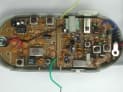
OJ78680501
Dec 06, 200149 MHz Long Range Walkie Talkie (Transmitter Part)
Equipment Class
DXT - Part 15 Low Power Transceiver, Rx Verified