OJ7APS-JESS001AQ Smart Speaker with Apple AirPlay
Victory Concept Industries Ltd
Click to zoom
Application Details
- Equipment Class
- DTS - Digital Transmission System
- Date of Grant
- Nov 29, 2011
- Application Purpose
- Original Equipment
- Date of Application
- Nov 29, 2011
- Equipment Note
- AQ Smart Speaker with Apple AirPlay
- Frequency Range
- 2412.00000000 - 2462.00000000
- Country
- Hong Kong
Documents & Files
Document Text
Text extracted from the exhibit documents filed with the FCC. Open a document above to read the original.
Users Manual
1 OWNER’S MANUAL AQ Smart Speaker with AirPlay 2 AQ Audio Limited Unit 5 Leestone Road Manchester M22 4RN www.aqaudio.com ©2011 AQ Audio. All rights reserved. Features, specifications and appearance are subject to change without notice. AQ Audio is a trademark of AQ Audio Limited, registered in the UK AirPlay, Apple, Mac, iPhone, iPod, iPod Nano, iPod Classic, iTunes and iPod Touch are trademarks of Apple Inc., registered in the U.S. and other countries. iPad is a trademark of Apple Inc. iPod/iPhone/iPad not included. “Made for iPod” and “Made for iPhone” mean that an electronic accessory has been designed to connect specifically to iPod and iPhone, respectively, and has been certified by the developer to meet Apple performance standards. Apple is not responsible for the operation of this device or its compliance with safety and regulatory standards. Wi-Fi is a registered trademark of the Wi-Fi Alliance. 3 Table of Contents Important Notices................................................................ 4 Introduction........................................................................ 4 Unpacking Your AQ Smart Speaker........................................ 5 AQ Smart Speaker Controls.................................................. 5 AQ Smart Speaker Connections............................................. 6 Charging Your AQ Smart Speaker.......................................... 7 AQ Smart Speaker Status LEDs............................................. 8 Connecting Your AQ Smart Speaker To Your Wireless Network.. 9 Setup Option 1 – Using The AQ Connect App...................... 9 Setup Option 2 – Manual Wireless Setup............................ 12 Using Your AQ Smart Speaker With AirPlay............................. 15 Using More Than One AQ Smart Speaker................................ 16 System Upgrade ................................................................. 17 System Reset...................................................................... 18 Troubleshooting Your AQ Smart Speaker................................ 19 Looking After Your Smart Speaker......................................... 22 Specification....................................................................... 23 4 Important Notices Important Note: Turn off the unit before inserting or unplugging audio cables from a source device’s headphone or line-level output jacks. Doing so will prolong the life of your unit, help protect your device from static electricity and prevent potential damage . WARNING: The USB Update port is designed to allow connection of a USB memory stick for firmware updates or Apple iPhone, iPod Touch or iPad for Network Setup only. DO NOT connect it to a computer or any other USB device, as damage may occur. For instructions, see pages 9 and 18 for more information. Introduction The AQ Smart Speaker is a totally wireless and totally portable audio system - it can play your audio and media anywhere around the house and garden direct from your Smartphone using your existing Wi-Fi network. The AQ Smart Speaker works with Apple’s AirPlay technology. It is able to wirelessly stream music from iTunes 10 on your Mac or PC, or from an iPhone, iPod Touch or iPad device with iOS 4.2 or later. Throughout this manual, when you see the term “iOS device”, it refers to any iPod, iPhone or iPad which is running Apple Operating System iOS 4.2 or later. With its leading edge and patented ultra-efficient high powered digital amplifier, the AQ Smart Speaker is able to deliver superb high quality sound from a 24W unit, giving up to 20 hours before recharge when using the Aux In connection, and over 10 hours in AirPlay mode. To conserve power, the Speaker also powers down after 10 minutes of inactivity (when in Airplay mode, and running on battery power). With more than one AQ Smart Speaker, you can build a stereo pair, or even an entire multi-room sound system. 5 Unpacking Your AQ Smart Speaker Carefully unpack your AQ Smart Speaker and confirm that all the items shown here are included. Please charge the Speaker before using it for the first time. AQ Smart Speaker Controls Volume Down Power/Mode Volume Up Power/Mode button: Press this button briefly to turn the AQ Smart Speaker on. Press and hold for 2 seconds to put it into the Standby mode. While in the Standby mode, the unit will still show the battery status. When the Power is on, briefly pressing the power button will switch between AirPlay and Aux In Mode. The Wi-Fi LED will switch off in Aux In mode. Volume Down button: Press this button to lower the volume. Press this button for more than 2 seconds to mute the sound, The power LED will flash whilst the sound is muted. When the sound is muted, press either the Volume Up or the Volume Down button to restore the sound. Volume Up button: Press this button briefly to raise the volume one step. Press this button for more than 0.5s to continuously raise the volume. 6 AQ Smart Speaker Connections 1 Æ 2 Æ Å 3 Å 4 Ç 5 1. Update port: The USB Update port is designed to allow connection of a USB memory stick for firmware updates or Apple iPhone, iPod Touch or iPad for Network Setup only. DO NOT connect it to a computer or any other USB device, as damage may occur. For instructions, see pages 9 and 18 for more information. 2. Aux In connector: For direct connection to an audio player or other audio device. Briefly press the power/mode button whilst the Speaker is switched on to switch between Aux In and Airplay mode. Playing music to the speaker from an Airplay device will automatically override Aux In mode and return the speaker to Wi-Fi operation. 3. Audio Mode Switch: Set to M if it is the only Speaker or if you are using it as part of a multi-room setup. Use L and R if you are using two Speakers as a stereo pair. 4. DC Power Connector: Connect to a mains power socket using the supplied power adaptor to charge the internal battery. The socket-outlet shall be installed near the equipment and shall be ea…
Text truncated - open the document above for the full version.
External Photos
EXHIBIT B - EUT EXTERNAL PHOTOGRAPHS EUT - Full View EUT - Front View EUT - Rear View EUT – Top View EUT – Bottom View
ID Label/Location Info
EXHIBIT A - FCC ID LABELING AND LOCATION FCC ID Label FCC ID Label Location The label shown shall be permanently affixed at a conspicuous location on the device and be readily visible to the user at the time purchase (Labeling requirements per 2.925)
Internal Photos
EXHIBIT C - EUT INTERNAL PHOTOGRAPHS EUT – Cover off View 1 Ant.location EUT – Cover off View 2 EUT – Main Board with RF Module TopView EUT – Main Board without RF Module Top View EUT – Main Board Bottom View EUT – RF Module Top View EUT – RF Module Shielding off Top View EUT – RF Module Bottom View EUT – Key Board Top View EUT – Key Board Bottom View EUT – Connect Board Top View EUT – Connect Board Bottom View EUT – Antenna View EUT – Battery View EUT – Adapter View EUT – Adapter Label View
Test Report
Note: This test report is prepared for the customer shown above and for the equipment described herein. It may not be duplicated or used in part without prior written consent from Bay Area Compliance Laboratories Corp. This report must not be used by the customer to claim product certification, approval, or endorsement by NVLAP*, or any agency of the Federal Government. * This report contains data that are not covered by the NVLAP accreditation and are marked with an asterisk “★” (Rev.2) FCC PART 15.247 TEST REPORT For Victory Concept Industries Ltd 4/F., CAC Tower, 165 Hoi Bun Road, Kwun Tong, Kowloon, Hong Kong Report Type: Original Report Product Type: AQ Smart Speaker with Apple AirPlay Test Engineer: Felix Li Report Number: RSZ111013003-00 Report Date: 2011-11-29 Reviewed By: Alvin Huang EMC Engineer Test Laboratory: Bay Area Compliance Laboratories Corp. (Shenzhen) 6/F, the 3rd Phase of WanLi Industrial Building, ShiHua Road, FuTian Free Trade Zone Shenzhen, Guangdong, China Tel: +86-755-33320018 Fax: +86-755-33320008 www.baclcorp.com.cn FCC ID: OJ7APS-JESS001 Bay Area Compliance Laboratories Corp. (Shenzhen) Report No.: RSZ111013003-00 FCC Part15.247 Page 2 of 41 TABLE OF CONTENTS GENERAL INFORMATION.......................................................................................................................................4 PRODUCT DESCRIPTION FOR EQUIPMENT UNDER TEST (EUT) .....................................................................................4 OBJECTIVE...................................................................................................................................................................4 RELATED SUBMITTAL(S)/GRANT(S).............................................................................................................................4 TEST METHODOLOGY..................................................................................................................................................4 TEST FACILITY.............................................................................................................................................................4 SYSTEM TEST CONFIGURATION ..........................................................................................................................6 DESCRIPTION OF TEST CONFIGURATION......................................................................................................................6 EUT EXERCISE SOFTWARE..........................................................................................................................................6 EQUIPMENT MODIFICATIONS.......................................................................................................................................6 EXTERNAL I/O CABLE..................................................................................................................................................6 CONFIGURATION OF TEST SETUP.................................................................................................................................7 BLOCK DIAGRAM OF TEST SETUP................................................................................................................................7 SUMMARY OF TEST RESULTS ...............................................................................................................................8 FCC §15.247 (i) & §2.1091- MAXIMUM PERMISSIBLE EXPOSURE (MPE)..........................................................9 APPLICABLE STANDARD..............................................................................................................................................9 FCC §15.203 - ANTENNA REQUIREMENT...........................................................................................................10 APPLICABLE STANDARD............................................................................................................................................10 ANTENNA CONNECTOR CONSTRUCTION....................................................................................................................10 FCC §15.207 (a) – AC LINE CONDUCTED EMISSIONS .....................................................................................11 APPLICABLE STANDARD............................................................................................................................................11 MEASUREMENT UNCERTAINTY..................................................................................................................................11 EUT SETUP................................................................................................................................................................11 EMI TEST RECEIVER SETUP.......................................................................................................................................12 TEST PROCEDURE......................................................................................................................................................12 TEST EQUIPMENT LIST AND DETAILS.........................................................................................................................12 TEST RESULTS SUMMARY..........................................................................................................................................12 TEST DATA................................................................................................................................................................12 FCC §15.209, §15.205 & §15.247(d) - SPURIOUS EMISSIONS.............................................................................15 APPLICABLE STANDARD............................................................................................................................................15 MEASUREMENT UNCERTAINTY..............................................................................…
Text truncated - open the document above for the full version.
Test Setup Photos
EXHIBIT C - TEST SETUP PHOTOGRAPHS Conducted Emissions- Front View Conducted Emissions- Side View Below 1 GHz: Spurious Radiated Emissions - Front View Below 1 GHz: Spurious Radiated Emissions - Rear View Above 1 GHz: Spurious Radiated Emissions - Front View Above 1 GHz: Spurious Radiated Emissions - Rear View
Contact Information
Applicant
Samuel Cheng(R & D Manager)
Test Firm
Bay Area Compliance Laboratory Corp. (Shenzhen)John Chan
Technical Specifications
| # | Rule Parts | Frequency Range | Power Output |
|---|---|---|---|
| 2 | 15C | 2.41 GHz - 2.46 GHz | 19.00 mW |
Other Applications from Victory Concept Industries Ltd
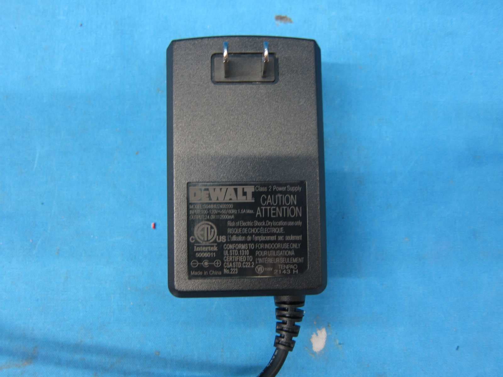
OJ7DWST08810
May 09, 2023ToughSystem Music + Charger
Equipment Class
DXX - Part 15 Low Power Communication Device Transmitter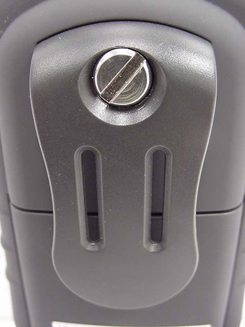
OJ7901GMR0903
Nov 04, 2003FRS/GMRS UHF Transceiver
Equipment Class
FRF - Part 95 Family Radio Face Held Transmitter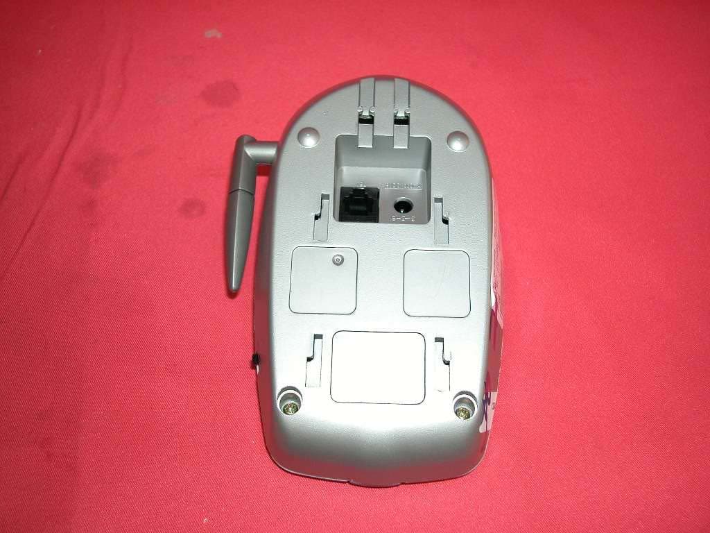
OJ7CTAVC2101102
Jan 15, 20032.4GHz 40 Channel Analog Modulation Cordless Phone
Equipment Class
DXT - Part 15 Low Power Transceiver, Rx Verified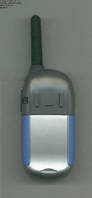
OJ7968FRS0401
Jan 03, 2002Family Radio Transceiver
Equipment Class
FRF - Part 95 Family Radio Face Held Transmitter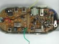
OJ78680501
Dec 06, 200149 MHz Long Range Walkie Talkie (Transmitter Part)
Equipment Class
DXT - Part 15 Low Power Transceiver, Rx Verified