OJF1RXUREMOTE EXTENDER UNIT
Corning Optical Communication LLC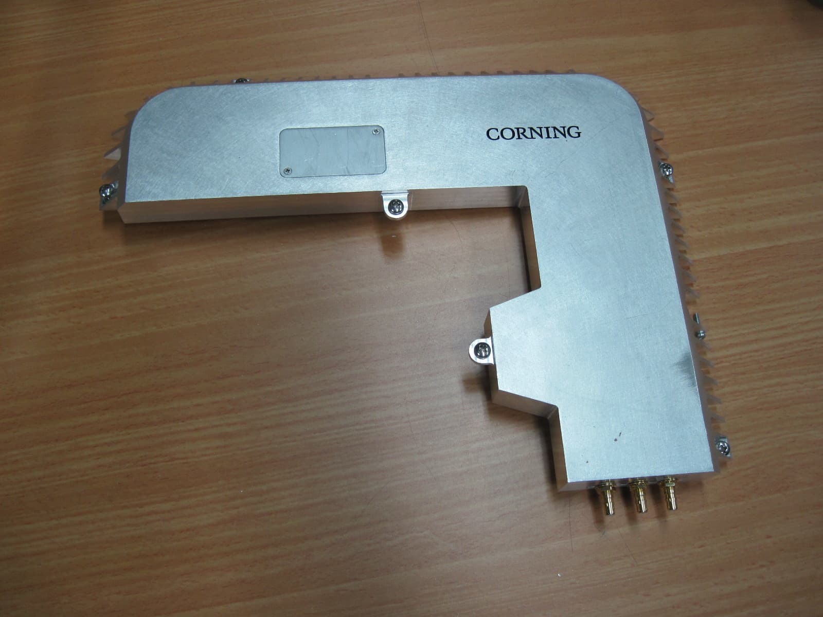
Click to zoom
Application Details
- Equipment Class
- TNB - Licensed Non-Broadcast Station Transmitter
- Date of Grant
- Sep 12, 2013
- Application Purpose
- Original Equipment
- Date of Application
- Sep 09, 2013
- Equipment Note
- REMOTE EXTENDER UNIT
- Frequency Range
- 2110.00000000 - 2155.00000000
- Country
- United States
Documents & Files
Document Text
Text extracted from the exhibit documents filed with the FCC. Open a document above to read the original.
Users Manual
• RxU Remote Expansion Unit Quick Installation Sheet Corning ONE ™ Wireless Platform CMA-261-AEN QUICK INSTALLATION SHEET | CMA-261-AEN | JULY 2013 | PAGE 1 OF 2 GENERAL INFORMATION 1. RxU expands the RAU band support to two additional MIMO bands. 2. RxU is assembled in the RAU enclosure (hot pluggable). Unit 1. PACKAGE CONTENTS Check your package contents to verify that the items in the packing list are included: Item Quantity Item Remote Expansion Unit (RxU) 1 2. ASSEMbLE Rxu IN RAu ENCLOSuRE Note: There is no need to disconnect the composite cable fiber and DC wires leading from the ceiling. Step 1: Remove the screw securing the bracket safety tab to the RAU (located above MGMT port). Step 2: Slide the RAU back into wide end of bracket screw holes so that it “clicks,” and remove unit. Step 3: Unscrew (five) screws securing the RAU enclosure cover and remove cover. See Figure 1 for location of screws. Figure 1. Removing RAU Enclosure Cover ONE ™ Wireless Platform This document describes the installation procedure for the ONE ™ Remote Expansion Unit (RxU). Remove Front Flap Remove Three Screws Remove Screw Remove Screw Step 3: Plug the RxU in to the right side of the RAU as indicated in Figure 2. RxU and RAU interface ports should face the same direction. Step 4: Replace the cover except for the front panel and screws, as shown in Figure 3 Figure 2. RxU Module Assembly Figure 3. Assembled RxU Interfaces Figure 4. RAU Enclosure LEDS 3. RF CONNECTIONS If required by site planner – connect the filter to the RF filter connectors on the RxU. Refer to Figure 3 for location of RAU and RxU filter connections. 5. VERIFY NORMAL OPERATION Step 1: Verify that LEDs on front cover indicate normal operation status: • RUN – Blinking green • POWER – Steady green • LINK – Steady green Refer to Figure 4 for LEDs. 4. ASSEMbLE RAu FRONT ACCESS PANEL AND REMOuNT 6. ASSEMbLE RAu FRONT ACCESS PANEL AND REMOuNT Corning MobileAccess, Inc. • 13221 Woodland Park Road, Suite 400 • Herndon, Virginia 20171 USA 866-436-9266 • FAX: 703-848-0280 • Tech Support Hotline: 410-553-2086 or 800-787-1266 • www.corning.com/mobileaccess Corning MobileAccess reserves the right to improve, enhance and modify the features and specifications of Corning MobileAccess products without prior notification. ONE is a trademark of Corning Cable Systems Brands, Inc. All other trademarks are the properties of their respective owners. Corning MobileAccess is ISO 9001 certified. © 2013 Corning MobileAccess. All rights reserved. Published in the USA. CMA-261-AEN / July 2013 QSG_GENII_RxU_709C012501_RevA00_19MAR13FINAL Run LED To External Filter To External Filter RxU RxU Module RAU To MIMO Service Antenna Power LED Link LED QUICK INSTALLATION SHEET | CMA-261-AEN | JULY 2013 | PAGE 2 OF 2 ONE ™ Wireless Platform
Users Manual
APRIL 2013 Corning ONE™ Wireless Platform User Manual Preface Material P/N 709C011801 Page 2 Preface Material About This Manual This user guide provides all the information necessary to understand the architecture and perform the installation of Corning® ONE™ Wireless Platform. Hardware Corning warrants to the original purchaser (“Customer”) that for the duration of the warranty period, one (1) year, commencing on the date of shipment of the Hardware, unless otherwise agreed in writing by Corning (the “Hardware Warranty Period”), the Hardware furnished by Corning shall be free in all material respects from defects in material and workmanship, and shall conform to the applicable portions of the Specifications, as defined below (the “Hardware Warranty”). If notified by Customer of any such defects in material or workmanship or nonconformity with applicable portions of the Specifications within the Hardware Warranty Period, Corning shall promptly, at its own election and expense, repair or replace any such Hardware proven to be defective under the terms of this Hardware Warranty. Such repair or replacement shall be Customer’s sole remedy and Corning sole obligation in the event this Hardware Warranty is invoked. If any components comprising a part of the Hardware are replaced or repaired during the Hardware Warranty Period, the Hardware Warranty Period for such repaired or replaced components shall extend to the longer of (i) the balance of the Hardware Warranty Period or (ii) three (3) months from the date of repair or replacement. For purposes of this Warranty, “Specifications” shall mean the specifications and performance standards of the Products as set forth in documents published by Corning and delivered to Customer which contain technical specifications or performance standards for the Products. If Customer invokes this Hardware Warranty, it shall notify Corning promptly of the claimed defect. Customer will allow Corning to inspect the Hardware at Customer’s location, or to return the Hardware to Corning closest repair facility. For Hardware returned to Corning repair facility, Customer shall be responsible for payment of all transportation and freight costs (including insurance) to Cornings’ repair facility, and Corning shall be responsible for all transportation and freight costs (including insurance) incurred in connection with the shipment of such Hardware to other repair facilities of Corning and/or its return to Customer. Notwithstanding the foregoing, in no event will Corning be liable for damage to Products resulting from improper handling during or after shipment, misuse, neglect, improper installation, operation or repair (other than by authorized Corning personnel), alteration, accident, or for any other cause not attributable to defects in materials or workmanship on the part of Corning. Corning shall not reimburse or make any allowance to Customer for any labor charges incurred by Customer for replacement or repair of any goods unless such charges are authorized in advance in writing by Corning. Preface Material P/N 709C011801 Page 3 Software Warranty Corning warrants to the original purchaser (“Customer”) that for the duration of the warranty period, one (1) year, commencing on the date of shipment of the Software, unless otherwise agreed in writing by Corning (the “Software Warranty Period”), the Software shall conform with, and perform the functions set forth in the Specifications, and shall be free from defects in material or workmanship (the “Software Warranty”). In the event the Software is proven to be defective under the terms of this Software Warranty, Corning shall correct such defects or failure and ensure that the Software conforms with, and performs the functions set forth in, the Specifications. Customer will allow Corning to inspect the Software at Customer’s location or to return it to Cornings’ closest repair facility. Notwithstanding the foregoing, Corning shall have no obligation under the Software Warranty if the Software is modified or used with hardware or software not supplied or approved by Corning or if the Software is subject to abuse, improper installation or application, accident, electrical or environmental over-stress, negligence in use, storage, transportation or handling. Third-party software distributed with the Software may carry certain warranties which, to the maximum extent allowed by law, Corning hereby assigns, transfers and otherwise conveys to Customer, provided, however, that Corning itself provides no warranty of any kind, express, implied, statutory or otherwise, for any third-party software provided hereunder. Corning does not warrant any hardware, software or services not provided by Corning. THIS WARRANTY IS THE ONLY WARRANTY MADE BY CORNING AND IS IN LIEU OF ALL OTHER WARRANTIES, EXPRESS OR IMPLIED INCLUDING, BUT NOT LIMITED TO, THE IMPLIED WARRANTIES OF MERCHANTABILITY AND FITNESS FOR A PARTICULAR PURPOSE. CORNING SHALL NOT BE LIABLE FOR ANY OTHER DAMAGE INCLUDING, BUT NOT LIMITED TO, INDIRECT, SPECIAL OR CONSEQUENTIAL DAMAGES ARISING OUT OF OR IN CONNECTION WITH FURNISHING OF GOODS, PARTS AND SERVICE HEREUNDER, OR THE PERFORMANCE, USE OF, OR INABILITY TO USE THE GOODS, PARTS AND SERVICE. CORNING SALES AGENTS OR REPRESENTATIVES ARE NOT AUTHORIZED TO MAKE COMMITMENTS ON WARRANTY RETURNS. Returns In the event that it is necessary to return any product against above warranty, the following procedure shall be followed: 1. Return authorization is to be received from Corning prior to returning any unit. Advise Corning of the model, Serial number, and discrepancy. The unit may then be forwarded to Corning, transportation prepaid. Devices returned collect or without authorization may not be accepted. 2. Prior to repair, Corning will advise the customer of our test results and any charges for repairing customer-caused problems or out-of-warranty conditions etc. 3. Repaired products are warranted for the balance of the original warr…
Text truncated - open the document above for the full version.
Cover Letter(s)
Date: 08 September 2013 FEDERAL COMMUNICATIONS COMMISSIONS Authorization and Evaluation Division 7435 Oakland Mills Road Columbia, MD 21046 Subject: Confidentiality Request regarding application for certification of FCC ID: OJF1RXU In accordance with Sections 0.457 and 0.459 of the Commission’s Rules, MobileAccess Networks hereby requests long-term confidential treatment of information accompanying this application as outlined below: CONF APPENDIX RXU BlkDia.pdf CONF APPENDIX RXU PartsLst.pdf CONF APPENDIX RXU Schem.pdf The above materials contain proprietary and confidential information not customarily released to the public. The public disclosure of these materials provides unjustified benefits to its competitors in the market. Sincerely, Steven Blum Product Manager Corning Mobileaccess 8391 Old Courthouse Rd Suite 300 Vienna VA 22182-3819 Corning MobileAccess 8391 Old Courthouse Road, Suite 300, Vienna, VA 22182 Tel: +1(866)436-9266, +1(703)848-0200 TAC: +1(800)787-1266, Fax: +1(703)848-0280 www.corning.com/mobileaccess
Cover Letter(s)
Date: 08 September 2013 To: Timco Engineering Inc. To Whom It May Concern We hereby authorize Mr. Shaike Raz of I.T.L. (Product Testing) Ltd (ITL) to sign Form 731 on our behalf regarding the FCC ID Certification Process for the following application: FCC ID: OJF1RXU Sincerely, Steve Blum Product Manager Corning Mobileaccess 8391 Old Courthouse Rd Suite 300 Vienna VA 22182-3819 Corning MobileAccess 8391 Old Courthouse Road, Suite 300, Vienna, VA 22182 Tel: +1(866)436-9266, +1(703)848-0200 TAC: +1(800)787-1266, Fax: +1(703)848-0280 www.corning.com/mobileaccess
Cover Letter(s)
Date: 08 September 2013 To: Timco Engineering Inc. To Whom It May Concern We hereby authorize Mr. Shaike Raz of I.T.L. (Product Testing) Ltd (ITL) to act on our behalf regarding the FCC ID Certification Process for the following application: FCC ID: OJF1RXU Sincerely, Steven Blum Product Manager Corning Mobileaccess 8391 Old Courthouse Rd Suite 300 Vienna VA 22182-3819 Corning MobileAccess 8391 Old Courthouse Road, Suite 300, Vienna, VA 22182 Tel: +1(866)436-9266, +1(703)848-0200 TAC: +1(800)787-1266, Fax: +1(703)848-0280 www.corning.com/mobileaccess
Cover Letter(s)
To: Feral Communications Commission From: Shaike Raz Att: Reviewing Engineer Reference No.: L132020.00 Date: 09 September 2013 Subject: FCC ID Application for Corning MobileAccess Remote Extender Unit (RXU) Module (FCC ID: OJF1RXU) To Whom it may concern, 1. We are submitting an application for Limited Modular approval on behalf of Corning MobileAccess for the above subject device placed in the Remote Antenna Unit host (FCC ID: OJF1C85P19L70A17). 2. The host user manual, label, and external photographs are being submitted as part of this application. 3. The Remote Extender Unit (RXU) Module (FCC ID: OJF1RXU) operates only in the host listed above. 4. Please let me know if you need any additional information. Regards, Shaike Raz EMC Laboratory Manager EMC Laboratory ITL (Product Testing) Ltd. Lod/Kfar Bin Nun Israel Tel: +972-8-9153100 Ext. 217 Fax: +972-8-915-3101 Email: [email protected]/[email protected] http://www.itl.co.il
ID Label/Location Info
TITLE: Drawn By: Yaakov S.Yaakov S. 05/03/06 Yossi G. Name: Signature: Date: Check: Approve: FCC PART 15 LABEL (23x85mm) PRODUCT P/N : Drawing No : MF0178401 276B093001 Rev : A02 Paper Size : A4 Sh : 1 of 1 This document contain confidential proprietary information and is the property of MobileAccess Networks Ltd. No use, Disclosure or reproduction is granted to any third parties without explicit written permission of MobileAccess Networks Ltd. REVISIONS REV. DESCRIPTION DATE APPROVED ECO No: NOTES : 1. ALL TEXT PRINTED SIZE 6 AND FONT STYLE TIMES NEW ROMAN. 2. POSITION COMPANY LOGO AS SHOWN ABOVE. Yossi G. Ofer Sh. 05/03/06 05/03/06 Golan Building Hagolan street & Hanegev street Airport City 70151 . CORNING MobileAccess Ltd. Ofer Sh. A01 Removing ONE logo . 24.06.13 C008052 Ofer Sh. A02 Adding FCC ID. 26.08.13 C008238 Ofer Sh. 2)This device must accept any interference received , This device complies with Part 15 of the FCC Rules. Operation is subject to the following two conditions: 1)This device may not cause harmful interference ,and operation. including interference that may cause undesired FCC ID: OJF1RXU
Operational Description
8391 Old Courthouse Road, Suite 300 Vienna, VA 22182 www.corning.com/mobileaccess ONE™ Distributed Antenna System RXU - Remote Extender Unit Operational Description General description Figure 1. RXU RXU is connected to main RAU module through RF and DC Connector. RXU is intended to add two additional frequency bands - LTE (728-757MHz) and AWS (2110-2155MHZ) – for MIMO 2x 2 operations. These two frequency bands are filtered and transmitted through additional antenna port via RF connector. Detailed description For the downlink the additional frequency band LTE and AWS from RAU module are connected to RXU through RF connector and split (via RF splitter) to 2 different LTE and AWS link and attenuate and equalize to bring the RF power level and slope to the right working point, the signal are amplitude via 4 RF amplifier and filter via saw filter (LTE/AWS saw filter) and amplifier with the power amplifier and filter again with LTE and 8391 Old Courthouse Road, Suite 300 Vienna, VA 22182 www.corning.com/mobileaccess AWS triplexer to transmit via antenna. In the uplink the signal that receive from antenna (LTE and AWS) are separate to 2 different link by the AWS and LTE triplexer, amplitude and attenuate via low noise amplifier and attenuator to bring the lever to the working point. The signal is amplitude via 3 RF amplifiers and combines the two links with RF combiner and connected to the RAU module with RF connector.
Parts List/Tune Up Info
Date: 2013 Sep 1 st DECLARATION The maximum output power level (dBm) and the tolerance (±dB) that the ONE™ RXU device is tuned to during the manufacturing process are as follows: Frequency Band (MHz) Max. Power Level (dBm) Deviation (dB) Emission Designator 728-758 15 2 all 2110-2155 17 2 all Sincerely, Steve Blum Product Manager Corning Mobileaccess 8391 Old Courthouse Rd Suite 300 Vienna VA 22182-3819 Corning MobileAccess 8391 Old Courthouse Road, Suite 300, Vienna, VA 22182 Tel: +1(866)436-9266, +1(703)848-0200 TAC: +1(800)787-1266, Fax: +1(703)848-0280 www.corning.com/mobileaccess
RF Exposure Info
2 1 cm mW 2 498. 01500 / cm mW f= R.F Exposure/Safety Calculation for RXU The E.U.T. is rack or wall mounted. The typical distance between the E.U.T. and the general population is >50cm. Calculation of Maximum Permissible Exposure (MPE) Based on Section 1.1307(b)(1) Requirements (a) FCC limit at 747 MHz is: FCC limit at 2135 MHz is: Using table 1 of Section 1.1310 limit for general population/uncontrolled exposures, the above level is an average over 30 minutes. (b) The power density produced by the E.U.T. is P t - Transmitted Peak Power (worst case) G T - Antenna Gain ,dBi R- Distance from Transmitter 2 4R GP S tt π = (c) Peak power density at worst case continuous transmission: Band Modulation Pt (mW) Antenna type G T (dBi) G T numeric R (cm) S AV (mW/cm 2 ) Spec (mW/cm 2 ) LTE LTE 64QAM 46.1 External 12.5 17.8 50 0.026 0.498 LTE 16QAM 45.7 External 12.5 17.8 50 0.026 0.498 LTE QPSK 48.6 External 12.5 17.8 50 0.028 0.498 AWS CDMA 116 External 12.5 17.8 50 0.065 1.0 LTE 64QAM 124 External 12.5 17.8 50 0.111 1.0 GSM 196 External 12.5 17.8 50 0.070 1.0 W-CDMA 146 External 12.5 17.8 50 0.083 1.0
Test Report
Test Report E126443.00 Corning MobileAccess Page 1 of 90 FCC ACC M Ver 1.1 05Mayl 2000 DATE: 29 August 2013 I.T.L. (PRODUCT TESTING) LTD. FCC Radio Test Report for Corning MobileAccess Equipment under test: ONE Distributed Antenna System Remote Extender Unit - RXU Written by: _____________________________ R. Pinchuck, Documentation Approved by: _____________________________ A. Sharabi, Test Engineer Approved by: _____________________________ I. Raz, EMC Laboratory Manager This report must not be reproduced, except in full, without the written permission of I.T.L. (Product Testing) Ltd. This report relates only to items tested. Test Report E126443.00 Corning MobileAccess Page 2 of 90 FCC ACC M Ver 1.1 05Mayl 2000 Measurement/Technical Report for Corning MobileAccess ONE Distributed Antenna System Remote Extender Unit - RXU ( FCC ID: OJF1RXU This report concerns: Original Grant: X Class II change: Class I change: Equipment type: PCB PCS Licensed Transmitter Limits used: 47CFR Parts 2; 27 Measurement procedure used is ANSI C63.4-2003. Substitution Method used as in ANSI/TIA-603-C: 2004 Application for Certification Applicant for this device: prepared by: (different from "prepared by") Ishaishou Raz Steve Blum ITL (Product Testing) Ltd. Corning MobileAccess Kfar Bin Nun 8391 Old Courthouse Rd., Suite #300 D.N. Shimshon 99780 Vienna, VA. 22182 Israel U.S.A. e-mail [email protected] Tel: +1-541-758-2880 Fax: +1-703-848-0260 e-mail: [email protected] Test Report E126443.00 Corning MobileAccess Page 3 of 90 FCC ACC M Ver 1.1 05Mayl 2000 TABLE OF CONTENTS 1. GENERAL INFORMATION ------------------------------------------------------------------------------- 5 1.1 Administrative Information ................................................................................. 5 1.2 List of Accreditations ......................................................................................... 6 1.3 Product Description ........................................................................................... 7 1.4 Test Methodology .............................................................................................. 7 1.5 Test Facility ....................................................................................................... 7 1.6 Measurement Uncertainty ................................................................................. 7 2. SYSTEM TEST CONFIGURATION --------------------------------------------------------------------- 8 2.1 Justification ........................................................................................................ 8 2.2 EUT Exercise Software ..................................................................................... 8 2.3 Special Accessories .......................................................................................... 8 2.4 Equipment Modifications ................................................................................... 8 2.5 Configuration of Tested System ........................................................................ 9 3. TEST SET-UP PHOTOS ----------------------------------------------------------------------------------10 4. RF POWER OUTPUT LTE -------------------------------------------------------------------------------13 4.1 Test Specification ............................................................................................ 13 4.2 Test procedure ................................................................................................ 13 4.3 Test Results..................................................................................................... 13 4.4 Test Equipment Used. ..................................................................................... 18 5. OCCUPIED BANDWIDTH LTE -------------------------------------------------------------------------19 5.1 Test Specification ............................................................................................ 19 5.2 Test Procedure ................................................................................................ 19 5.3 Test Results..................................................................................................... 20 5.4 Test Equipment Used. ..................................................................................... 30 6. SPURIOUS EMISSIONS AT ANTENNA TERMINALS LTE -------------------------------------31 6.1 Test Specification ............................................................................................ 31 6.2 Test procedure ................................................................................................ 31 6.3 Test Results..................................................................................................... 31 6.4 Test Equipment Used ...................................................................................... 35 7. BAND EDGE SPECTRUM LTE-------------------------------------------------------------------------36 7.1 Test Specification ............................................................................................ 36 7.2 Test procedure ................................................................................................ 36 7.3 Results ............................................................................................................. 36 7.4 Test Equipment Used. ..................................................................................... 40 8. SPURIOUS RADIATED EMISSION LTE -------------------------------------------------------------41 8.1 Test Specification ............................................................................................ 41 8.2 Test Procedure ................................................................................................ 41 8.3 Test Results..................................................................................................... 42 8.4 Test Instrumentation Used, Radiated Measurements .........................…
Text truncated - open the document above for the full version.
Contact Information
Applicant
Dana Whitney(Director of Operations and Program)
Test Firm
Israel Testing LaboratoriesIIan Cohen
Technical Specifications
| # | Rule Parts | Frequency Range | Power Output | Emission | Tolerance |
|---|---|---|---|---|---|
| 6 | 27 | 2.11 GHz - 2.15 GHz | 146.00 mW | F9W | Amp |
Other Applications from Corning Optical Communication LLC

OJFE62-N3-7US
Aug 29, 2024Remote Unit, Radio Node
Equipment Class
B2I - Part 20 Industrial Booster (CMRS)
OJFDHRU-G2-19
Apr 09, 2024HRU Digital High Power Amplifier Module supporting PCS
Equipment Class
B2I - Part 20 Industrial Booster (CMRS)
OJFDLRUG2678
Oct 17, 2023Low Band dRAU
Equipment Class
B2I - Part 20 Industrial Booster (CMRS)
OJFDMRUG22325
Jul 31, 2023digital Medium-power Remote Unit
Equipment Class
B2I - Part 20 Industrial Booster (CMRS)
OJFDMRUG2678
Jul 30, 2023digital Medium-power Remote Unit
Equipment Class
B2I - Part 20 Industrial Booster (CMRS)