OJFDLRU1719235Medium Band dRAU
Corning Optical Communication LLC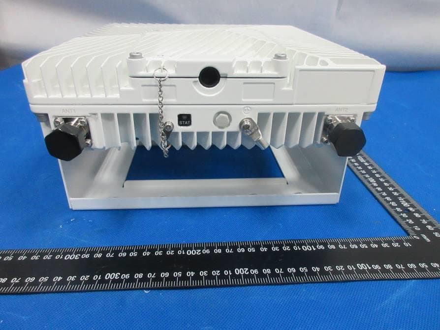
Click to zoom
Application Details
- Equipment Class
- B2I - Part 20 Industrial Booster (CMRS)
- Date of Grant
- Jan 23, 2021
- Application Purpose
- Original Equipment
- Date of Application
- Jan 23, 2021
- Equipment Note
- Medium Band dRAU
- Frequency Range
- 2496.00000000 - 2690.00000000
- Country
- United States
Documents & Files
Document Text
Text extracted from the exhibit documents filed with the FCC. Open a document above to read the original.
Users Manual
Corning Optical Communications www.corning.com Corning Everon™ 6000 DAS Solutions Specification Sheet Everon 6000 DAS Specification Sheet Everon 6000 data sheet P-N CE0012001 15-Jan-2021.docx| CORNING | Everon 6000 | Specification Sheet P/N :CE0012001| Page 2 of 24 Features and benefits | Comprehensive service Support 600 MHz, 700 MHz, FirstNet, 800/850 MHz, 1900 (PCS), EAWS, 2.3 GHz (WCS), 2.5 GHz (TDD). Support of SISO and MIMO services, FDD and TDD formats. Supports 3G, 4G, 5G technologies Multi-X system Supports multi-operator, multi-band, multi-technology services over a single infrastructure. Supports single and multi-building (“campus”) network architectures Highly modular/ Highly scalable Can be easily expanded to support additional capacity: sectors, frequency bands, channels and coverage areas via extending the number of remotes Advanced Digital Signal Processing Provides higher dynamic range, enables per channel granularity, delivers enhanced overall power efficiency and improves overall system performance Digital CPRI based Transport Provides robust signal distribution. Ready for future direct interfaces interoperability with digital based capacity sources (e.g. BBUs/DUs) Digital Service and capacity routing Enables advanced capacity and coverage management through flexible routing configuration management Carrier-grade network management Network configuration and management capabilities enable on-site as well as remote end-to-end configuration, system diagnostics, maintenance, support management and control by operators NOC Corning Everon 6000 DAS is an advanced in- building cellular service solution for small, medium and large size venues, supporting a broad range of cellular generations:3G,4G and 5G. Corning Everon 6000 DAS is based on digital distribution architecture, advanced digital processing, and channelized implementation, enabling efficient utilization of digital links. The solution is designed to support multi- band, multi-technology and multi-operator networks over a single fibre-based infrastructure. Corning Everon 6000 high bandwidth distribution architecture provides preparedness for future radio technologies, broader spectrum, and new frequency bands. Due to its modular design and configuration flexibility, Corning Everon 6000 is highly scalable in terms of supported capacity (number of sectors, frequency bands, channels) and remote units (coverage), and can be easily configured to support a large variety of deployment scenarios including single and multi-building (“Campus”) network topologies. Corning Everon 6000 offers multiple types of digital remote units, supporting a variety of frequency band combinations, SISO/MIMO configurations, with different power levels ranging from 20 dBm per band to 43 dBm per band. Advanced network configuration and management capabilities enable on-site as well as remote end-to-end configuration, system diagnostics, maintenance and support operators NOC connectivity. Everon 6000 Specification Sheet Everon 6000 data sheet P-N CE0012001 15-Jan-2021.docx| CORNING | Everon 6000 | Specification Sheet P/N :CE0012001 |Page 3 of 24 System architecture -Everon 6000 | Radio Interface Frames (Point of Interface) Radio Interface frames are modular chassis used for interface between the base stations and the Everon 6000. A system may be comprised of two types of Chassis: IHU (Integrated Head-end Unit) and HEU (Head End Unit). The IHU can interface up to 8 RF duplexed ports (or 16 UL/DL simplex ports) and can be expanded by an HEU radio interface frame which provides interface capabilities for additional 12 RF duplexed ports (or 24 UL/DL simplex ports). The following modules are used with the radio interface frames: • RIMe (Radio Interface Module Enhanced ) - provides an interface and signal conditioning to signals coupled between the signal source RF antenna ports and the Everon 6000 (uplink and downlink) • DCM (Digital Conversion Module) - Provides RF to CPRI (Downlink) and CPRI to RF (Uplink) conversion, where the well-known CPRI (Common Public Radio Interface) standard is used for representing the RF signals. Each DCM may convert signals capturing up to 190 MHz aggregated bandwidth. • RIX (Radio Interface Expander) – combines downlink signals of the HEU and IHU RIMe’s and provides the combined signals to the OIX, splits uplink signals arriving from the OIX to the HEU and IHU RIMe’s. • OIX (Optical Interface Expander) – combines downlink signals arriving from the HEU RIX and the IHU RIX and splits the uplink signal for the HEU RIX and the IHU RIX uplink ports. • PSM (Power Supply Module) – provides power to the radio interface frame • dHCM (Digital Head-End Control Module) is a “master” frame controller • ACM (Auxiliary Control Module) is a “slave” frame controller controlled by the dHCM Everon 6000 Specification Sheet Everon 6000 data sheet P-N CE0012001 15-Jan-2021.docx| CORNING | Everon 6000 | Specification Sheet P/N :CE0012001 |Page 4 of 24 DRU – Digital Routing Unit The DRU - Digital Routing Unit is the Everon 6000 central Hub and Distribution element. The DRU interfaces between the DCM modules and the IHU Radio Interface Frames, allowing to receive the operators service signals in CPRI format, and to route these signals to the remote antenna units. The DRU supports all Corning digital remote antenna units’ flavours, for all services, power levels and antenna configurations (SISO or MIMO). Each DRU includes 4 SFP+ ports connected to the DCMs and 32 SFP+ ports for connection to the remote units. When more remote antenna units are needed, the system scales up easily by adding additional system modules. LRU - Low power Remote Unit The LRU is a low power remote antenna unit with 20 dBm per MIMO stream per band output RF power and native support of 2x2 MIMO antenna scheme. Two types of LRU are available: Low band LRU - supports 600 MHz (band 71), 700 MHz Low (band 12), 700 MHz High (bnad13), FirstNet (band 14), 800/850 MHz (band 26) band…
Text truncated - open the document above for the full version.
Users Manual
Everon™ 6000 v1.0 User Manual Corning Optical Communications www.corning.com User Manual Corning Restricted and Confidential Proprietary Everon™ 6000 v1.0 User Manual Proprietary Information The information contained in this document is the sole property of Corning. The Disclosure of this information does not constitute the release of any proprietary rights therein. Permission to reproduce this information or parts disclosed herein must be obtained in writing from Corning. User Manual v1.0 Corning Restricted and Confidential Proprietary - Controlled content UM - Everon 6000 DAS - 19-DEC-2020.docx| December 2020 |Page 3 of 170 Preface Material About this Manual This manual describes how to install, use, configure and manage Corning’s Everon™ 6000 1.0 platform. It includes a description of the system end-to-end first time and on-going configuration, management and maintenance. Intended Users and Scope This manual is intended for Corning system installers, technicians and users. It is assumed that the user is familiar with the system and its units, and understands the basic functionality of the system. Contacting Technical Support HelpDesk Corning technical support contact information: email: [email protected] Tel: [800] 787 1266 Legal Notice Copyright Copyright © 2020 Corning., All Rights Reserved Disclaimer This document contains proprietary information of Corning and may not be reproduced in any form without the prior written consent of Corning. No part of this document may be reproduced, translated, stored in a retrieval system or transmitted in any form and by any means, electronic, mechanical, photographic, photocopying, recording, or otherwise, without the prior written permission of Corning. Information provided in this document is subject to change without notice and does not represent a commitment on the part of Corning. All products and company names are trademarks or registered trademarks of their respective holders. Software License Terms The software and the system design is the property of Corning. It is supplied to the user to be used solely for its stated purposes. It is strictly forbidden to make copies of the software or transfer it in any way, for any purpose, to any third party. The license to use the software is granted to the user only for the specific system it is installed on by Corning, or its authorized distributors and representatives. User Manual v1.0 Corning Restricted and Confidential Proprietary - Controlled content UM - Everon 6000 DAS - 19-DEC-2020.docx| December 2020 |Page 4 of 170 The purchaser shall not modify the software in any way. It is strictly forbidden to use this product for any purpose other than originally designated for or stipulated by Corning. Conventions Important information is highlighted in a frame, as explained below: Warning: Actions requiring special attention to avoid serious bodily injury; For example, working with high voltage components Caution: Actions requiring special attention, to avoid possible damage to equipment Note: Hints and recommendations for working efficiently User Manual v1.0 Corning Restricted and Confidential Proprietary - Controlled content UM - Everon 6000 DAS - 19-DEC-2020.docx| December 2020 |Page 5 of 170 Warranties Hardware Warranty Corning Optical Communications Wireless, Inc. (“Corning”)warrants to the original purchaser (“Customer”) that for the duration of the warranty period, one (1) year, commencing on the date of shipment of the Hardware, unless otherwise agreed in writing by Corning (the “Hardware Warranty Period”), the Hardware furnished by Corning shall be free in all material respects from defects in material and workmanship, and shall conform to the applicable portions of the Specifications, as defined below (the “Hardware Warranty”). If notified by Customer of any such defects in material or workmanship or nonconformity with applicable portions of the Specifications within the Hardware Warranty Period, Corning shall promptly, at its own election and expense, repair or replace any such Hardware proven to be defective under the terms of this Hardware Warranty. Such repair or replacement shall be Customer’s sole remedy and Corning’s sole obligation in the event this Hardware Warranty is invoked. If any components comprising a part of the Hardware are replaced or repaired during the Hardware Warranty Period, the Hardware Warranty Period for such repaired or replaced components shall extend to the longer of (i) the balance of the Hardware Warranty Period or (ii) three (3) months from the date of repair or replacement. For purposes of this Warranty, “Specifications” shall mean the specifications and performance standards of the Products as set forth in documents published by Corning and delivered to Customer which contain technical specifications or performance standards for the Products. If Customer invokes this Hardware Warranty, it shall notify Corning promptly of the claimed defect. Customer will allow Corning to inspect the Hardware at Customer’s location, or to return the Hardware to Corning’s closest repair facility. For Hardware returned to Corning’s repair facility, Customer shall be responsible for payment of all transportation and freight costs (including insurance) to Corning’s repair facility, and Corning shall be responsible for all transportation and freight costs (including insurance) incurred in connection with the shipment of such Hardware to other repair facilities of Corning and/or its return to Customer. Notwithstanding the foregoing, in no event will Corning be liable for damage to Products resulting from improper handling during or after shipment, misuse, neglect, improper installation, operation or repair (other than by authorized Corning personnel), alteration, accident, or for any other cause not attributable to defects in materials or workmanship on the part of Corning. Corning shall not reimburse or make any allowance to Customer for any labor charges incurred by Customer …
Text truncated - open the document above for the full version.
Users Manual
User Manual v1.0 Corning Restricted and Confidential Proprietary - Controlled content UM - Everon 6000 DAS - 19-DEC-2020.docx| December 2020 |Page 76 of 170 2.6.1 Verify Box Contents 2. Open the package and verify all elements are available according to the following table: Table 9: HEU Package Items List Item Quantity Image Part Number HARDWARE – provided in the box Headend Unit Chassis (with blank panels on RIM and one PSM slots) – includes factory installed Fan Module (FAM) in chassis rear 1 FAM Fan Module (FAM) – single unit hosting 4 fans (factory installed in chassis rear) 1 RJ45/RJ45 communication cable L=2m-2.15m (P/N 705900003) – HCM management cable 1 RIM kit: Radio Interface Module (service specific) 1-12 (according to order) RIX Module Kit Radio Expander Module – expands the RF sources to the OIU 1 or 2 (according to order) Pilot Transport Cable (P/N: PCKC47*) – Single QMA to QMA cable; L = 47 in; used for passing reference clock signal connections between RIX modules. *Additional lengths can be ordered: • PCKC20: L=20 in • PCKC63: L=63 in • PCKC79: L=79 in 1 User Manual v1.0 Corning Restricted and Confidential Proprietary - Controlled content UM - Everon 6000 DAS - 19-DEC-2020.docx| December 2020 |Page 77 of 170 Item Quantity Image Part Number ERFC (Expander Cable) - RF interface cable to HEU; 9 pin SMP to SMP connector Available in five different lengths: • ERFC16: L= 16 in • ERFC24: L= 24 in • ERFC34: L= 34 in • ERFC40: L= 40 in • ERFC59: L= 59 in 1 DCM kit Optical cables Up to 900 meters LC/UPC SM DX SFP+ Pluggable Transceivers (hot-pluggable optical transceiver module); Support for option 8 line-rate 10.1 Gbps, single mode ETM Kit: ETM Expander Termination Module (for unused Expander slot) unit 1 PSM Kit (AC or DC modules): • PSM-AC: 100-240 VAC Power Supply Module including standard IEC 60320-1 C13 cable • PSM-DC: 48 V DC Power Supply Module; 9 A Max.; Includes six pin terminal block connector 1 or 2 kits (according to order) User Manual v1.0 Corning Restricted and Confidential Proprietary - Controlled content UM - Everon 6000 DAS - 19-DEC-2020.docx| December 2020 |Page 78 of 170 Item Quantity Image Part Number Controller Module Kit (HCM or ACM - according to order) • dHCM Kit (Headend Control Module) – installed in Main HEU unit; enables remote/local management of all hosted units • ACM Kit (Auxiliary Control Module) – installed in Auxiliary HEU units; provides management connections for the Auxiliary HEU. User Manual v1.0 Corning Restricted and Confidential Proprietary - Controlled content UM - Everon 6000 DAS - 19-DEC-2020.docx| December 2020 |Page 79 of 170 2.6.2 Mount the Chassis in a Rack Notes: • One HEU supports connections to up to four IHUs • IHU chassis requires 4U rack height availability • Rack nuts and screws not provided 1. Determine the location of the HEU in the rack while considering additional HEU and IHU units and the lengths of the available ERFC cable. 2. Refer to Error! Reference source not found. for planning the rack positions. 3. Secure the units’ rack ears to the rack frame as follows: • Insert two screws half-way into the rack frame. • Position the chassis on to the screws using the handles and the top and bottom half slots of the rack ears. • Secure the unit in the rack via all applicable bracket holes using the appropriate rack nuts and screws. Installing Chassis in Rack User Manual v1.0 Corning Restricted and Confidential Proprietary - Controlled content UM - Everon 6000 DAS - 19-DEC-2020.docx| December 2020 |Page 80 of 170 2.6.3 Install the Modules in the Chassis Note: For modules with ejectors (i.e. RIM, RIX OIM, OIX, DCM and HCM/ACM) – verify that the ejectors are completely open when inserting in dedicated slot and then push in until the module clicks in to the backplane. See Figure 13: Module Captive Screws and Ejectors below, that shows an example of module type captive screws and ejectors. 2.6.3.1 Install the DCM Module 1. Slide the DCM to its slot in the HEU chassis 2. Secure the DCM to the Rack with the 2 captive screws 2.6.3.2 Install the rest of the Modules Refer to Figure 12: IHU Interfaces and Slots for module locations. Remove blank panel and slide in the relevant module (chassis slots are 100% mistake proof): • (One) HCM (for Standalone/Master HEU units) / (One) ACM (for Auxiliary HEU unit) • (One to two) PSM – for single power supply installations, install the PSM in either (PSM) slot • (One) RIX module • (One to eight) RIM – no need to terminate unoccupied RIM slot • (One to two) DCM • (One) RIX Referring to the following figure, secure the modules to the backplane by: • Closing the ejectors (for relevant modules) • Tightening the captive screws Captive screws User Manual v1.0 Corning Restricted and Confidential Proprietary - Controlled content UM - Everon 6000 DAS - 19-DEC-2020.docx| December 2020 |Page 81 of 170 Figure 13: Module Captive Screws and Ejectors User Manual v1.0 Corning Restricted and Confidential Proprietary - Controlled content UM - Everon 6000 DAS - 19-DEC-2020.docx| December 2020 |Page 82 of 170 2.6.4 Connect the Cables 2.6.4.1 Ground The grounding connection is performed via a two-hole, standard barrel grounding lug located on the HEU rear panel. • For use with stranded copper wire conductors • 10-14 AWG • Holes - 1/4 inch Grounding Lug (Chassis Rear) 2.6.4.2 Connect RIMS to RF Source(S) For each RIM - connect the external RF source to the corresponding RIM (service specific) Simplex or Duplex QMA connectors: a. For each RIM - connect the RF coax cable to the RIM’s Simplex or Duplex QMA connectors. b. Route the connected cables through the Cable Management Tray towards the right or left of the tray (depending on the module location in the chassis). c. Connect the RF coax cable from the RIM to the corresponding external RF source. RIMs connections User Manual v1.0 Corning Restricted and Confidential Proprietary - Controlled content UM - Everon 6000 DAS - 19-DEC-2020.docx| December 2020 |Page 83 of 170 2.6…
Text truncated - open the document above for the full version.
Attestation Statements
Corning Optical Communication Wireless © 2020 Corning Incorporated. All Rights Reserved. To: SGS North America Inc. 620 Old Peachtree Road SUITE 100 Suwanee, Georgia United States From: Corning Optical Communication Wireless 8253 1st AveVienna, 22182, Virginia, United States Confidentiality Request regarding application for FCC ID:OJFDLRU1719235 Regarding: According to: FCC KDB 935210 D02 Signal Boosters Certification v04r02 For PART 90 booster device, Section V (g) requirement: (g) Attestation (must be non-confidential exhibit, signed by the applicant; signature by test lab, agent, or TCB is not acceptable) should include: (1) Warning label messages and Class B disclosure will be also shown in online and point-of-sale marketing materials and on outside packaging of device: For PART 20 booster device, IV.(d) requirement: (d)Attestation (must be non-confidential exhibit, signed by the applicant; signature by test lab, agent, or TCB is not acceptable) should include: (1) Warning label messages will be also shown in online and point-of-sale marketing materials and on outside packaging of device we Corning Optical Communication Wireless declared our Warning label messages and Class B disclosure will be also shown in online and point-of-sale marketing materials and on outside packaging of device. For FCC ID: OJFDLRU1719235; Model number: dLRU-17192325, Medium Band dRAU WARNING. This is NOT a CONSUMER device. It is designed for installation by FCC LICENSEES and QUALIFIED INSTALLERS. You MUST have an FCC LICENSE or express consent of an FCC Licensee to operate this device. Unauthorized use may result in significant forfeiture penalties, including penalties in excess of $100,000 for each continuing violation. Corning Optical Communication Wireless © 2020 Corning Incorporated. All Rights Reserved. Sincerely, Title: Director, Product Management On behalf of company: Corning Optical Communication Wireless
Cover Letter(s)
Corning Optical Communication Wireless © 2020 Corning Incorporated. All Rights Reserved. Date: 12/23/2020 TO: Federal Communication Commission Equipment Authorization Branch 7435 Oakland Mills Road Columbia, MID 21046 Regarding: FCC ID: OJFDLRU1719235 To whom it may concern: We, the undersigned, hereby authorize SGS-CSTC Standards Technical Services Co., Ltd. (SGS) Guangzhou branch and Kobe Jian in SGS-CSTC Standards Technical Services Co., Ltd. (SGS) Guangzhou branch to act on our behalf in all manners relating to application for equipment authorization with respect to the FCC ID above, including signing of all documents relating to these matters. Any and all acts carried out by the agent on our behalf shall have the same effect as acts of our own. We, the undersigned, hereby certify that we are not subject to a denial of federal benefits, that includes FCC benefits, pursuant to Section 5301 of the Anti-Drug Abuse Act of 1988, 21 U.S.C. 853(a). Where our agent signs the application for certification on our behalf, I acknowledge that all responsibility for complying with the terms and conditions for Certification, as specified by SGS North America, Inc., still resides with Corning Optical Communication Wireless. This authorization is valid until further written notice from the applicant. Name (Printed): Isaac Nissan Title: Direector of Market Development Signature: On behalf of Company: Corning Optical Communication Wireless
Cover Letter(s)
SGS North America Inc. 620 Old Peachtree Road SUITE 100 Suwanee, Georgia 30024 United States Applicant Declaration Applicant Legal Business Name Corning Optical Communication Wireless Address 8253 1st AveVienna, 22182, Virginia, United States Grantee Code OJF FCC ID OJFDLRU1719235 Authorized Contact Name Isaac Nissan Contact Email [email protected] Contact Phone 703-855-1773 I, the undersigned, certify that I am an authorized signatory for the Applicant and therefore declare; a) in accordance with 47CFR2.911(d), all of the statements herein and the exhibits attached hereto are true and correct to the best of my knowledge and belief. b) in accepting a Grant of Equipment Authorization issued by a TCB, under the authority of the FCC, as a result of the representations made in this application, the Applicant is responsible for: (1) labeling the equipment with the exact FCC ID as specified in this application, (2) compliance statement labeling pursuant to the applicable rules, (3) compliance of the equipment with the applicable technical rules, c) if the Applicant is not the actual manufacturer of the equipment, appropriate arrangements have been made with the manufacturer to ensure that production units of this equipment will continue to comply with the FCC’s technical requirements. d) in accordance with 47 CFR 2.909 and KDB394321, the Applicant has read, understood and agrees to accept that they are the responsible party and agree to abide by their responsibilities as specified under 47 CFR 2.909 and KDB394321. e) in accordance with ISO17065, FCC KDB641163, FCC KDB610077, KDB394321 and RSP-100, the Applicant has read, understood, accepts and agrees to abide by the post market surveillance requirements. (1) the Applicant understands, accepts and agrees that a sample may be requested for surveillance testing. (2) the Applicant shall make provisions to always have a production sample available upon request by SGS, FCC and/or ISED. (3) the Applicant shall, upon request by SGS, at the Applicant’s expense, provide a production sample of the requested product to SGS, FCC and/or ISED as instructed. The sample shall include all support devices, cables, software, accessories or other hardware or software required for evaluation, review, certification and audit surveillance of products certified by SGS. f) neither the Applicant nor any party to the application is subject to a denial of Federal benefits, that includes FCC benefits, pursuant to Section 5301 of the Anti-Drug Abuse Act of 1988, 21 U.S.C. §862 because of a conviction for possession or distribution of a controlled substance. See 47CFR 1.2002(b) for the definition of a “party” for these purposes. g) the Applicant has read, understood, accepts and agrees to abide by the SGS North America, Inc.(TCB) terms and conditions. Link to CFRs: https://www.fcc.gov/wireless/bureau-divisions/technologies-systems-and-innovation-division/rules-regulations-title-47 Link to KDBs: https://apps.fcc.gov/oetcf/kdb/index.cfm Link to RSP-100: https://www.ic.gc.ca/eic/site/smt-gst.nsf/eng/sf01130.html Applicant Signature: Date:12/23/2020 Print Name: Isaac Nissan Title: Direector of Market Development *NOTE: This declaration cannot be signed by an Agent, it shall be signed by an authorized person listed in the FCC database Applicant Declaration Rev:0.0
Cover Letter(s)
Corning Optical Communication Wireless To: SGS North America Inc. 620 Old Peachtree Road SUITE 100 Suwanee, Georgia United States From: Corning Optical Communication Wireless 8253 1st Ave Vienna, Virginia, 22182, United States Regarding: Confidentiality Request regarding application for FCC ID: OJFDLRU1719235 LONG TERM CONFIDENTIALITY Pursuant to 47 CFR Section 0.459 and 0.457 of the commission’s rules, the applicant hereby request confidential treatment of the documents listed below, associated with the certification application referenced above. Schematic(s) Block Diagrams Operational Descriptions The documents above contain proprietary information not released to the public. Public disclosure of this information may prove harmful to the business of the applicant. SHORT TERM CONFIDENTIALITY Additionally, the applicant requests the following documents be held confidential until the device is marketed or 180 days from the grant date, whichever is less. If the device is marketed within 180 days of the Grant Date, the applicant will notify the TCB per FCC KDB 726920 D01 Confidentiality Request Procedures. User manual(s) Sincerely, Name (Printed): Isaac Nissan Title: Direector of Market Development Signature: On behalf of Company: Corning Optical Communication Wireless
External Photos
External Photo
ID Label/Location Info
dLRU-17192325 Label Design Product label (57mm x 25mm): Location: Warning label (68mm x 26mm): Location:
Internal Photos
Internal Photo
RF Exposure Info
SGS-CSTC Standards Technical Services Co., Ltd. Guangzhou Branch Page: 1 of 4 FCC ID: OJFDLRU1719235 This document is issued by the Company subject to its General Conditions of Service printed overleaf, available on request or accessible at www.sgs.com/terms_and_conditions.htm and, for electronic format documents, subject to Terms and Conditions for Electronic Documents at www.sgs.com/terms_e-document.htm. Attention is drawn to the limitation of liability, indemnification and jurisdiction issues defined therein. Any holder of this document is advised that information contained hereon reflects the Company’s findings at the time of its intervention only and within the limits of Client’s instructions, if any. The Company’s sole responsibility is to its Client and this document does not exonerate parties to a transaction from exercising all their rights and obligations under the transaction documents. This document cannot be reproduced except in full, without prior written approval of the Company. Any unauthorized alteration, forgery or falsification of the content or appearance of this document is unlawful and offenders may be prosecuted to the fullest extent of the law. Unless otherwise stated the results shown in this test report refer only to the sample(s) tested and such sample(s) are retained for 90 days only. Product operation frequency range and FCC ID number information. Model number: dLRU-17192325 Operation frequency band: AWS-1 Uplink: 1710MHz to 1755MHz Downlink: 2110MHz to 2155MHz AWS-2 Uplink: 1755MHz to 1780MHz Downlink: 2155MHz to 2180MHz Broadband PCS Uplink: 1850MHz to 1915MHz Downlink: 1930MHz to 1995MHz WCS Uplink: 2305MHz to 2315MHz Downlink: 2350MHz to 2360MHz BRS/EBS Uplink: 2496MHz to 2690MHz Downlink: 2496MHz to 2690MHz Supported signal modulation type: 3G WCDMA LTE 5G NR Input signal channel space: Band Technology Supported Bandwidth AWS-1/AWS-2/ Broadband PCS 3G 5MHz 4G 5/10/15/20MHz 5G 5/10/15/20MHz WCS 4G 5/10MHz 5G 5/10MHz BRS/EBS 4G 5/10/15/20MHz 5G 5/10/15/20/40/60MHz FCC ID: OJFDLRU1719235 RF Exposure Compliance Requirement SGS-CSTC Standards Technical Services Co., Ltd. Guangzhou Branch Page: 2 of 4 FCC ID: OJFDLRU1719235 This document is issued by the Company subject to its General Conditions of Service printed overleaf, available on request or accessible at www.sgs.com/terms_and_conditions.htm and, for electronic format documents, subject to Terms and Conditions for Electronic Documents at www.sgs.com/terms_e-document.htm. Attention is drawn to the limitation of liability, indemnification and jurisdiction issues defined therein. Any holder of this document is advised that information contained hereon reflects the Company’s findings at the time of its intervention only and within the limits of Client’s instructions, if any. The Company’s sole responsibility is to its Client and this document does not exonerate parties to a transaction from exercising all their rights and obligations under the transaction documents. This document cannot be reproduced except in full, without prior written approval of the Company. Any unauthorized alteration, forgery or falsification of the content or appearance of this document is unlawful and offenders may be prosecuted to the fullest extent of the law. Unless otherwise stated the results shown in this test report refer only to the sample(s) tested and such sample(s) are retained for 90 days only. 1. Standard requirement Systems operating under the provisions of this section shall be operated in a manner that ensures that the public is not exposed to radio frequency energy level in excess limit for maximum permissible exposure. In accordance with 47 CFR FCC Part 2 Subpart J, section 2.1091 this device has been defined as a mobile device whereby a distance of 0.2m normally can be maintained between the user and the device. (a) Limits for O…
Text truncated - open the document above for the full version.
Contact Information
Applicant
Dana Whitney(Director of Operations and Program)
Technical Contact
SGS-CSTC Standards Technical Services Co., LtdKobe Jian
[email protected]86-20-82155314
198 KEZHU Road, Scientech Park, Guangzhou Economic · Guangzhou · China
Non-Technical Contact
SGS-CSTC Standards Technical Services Co., LtdKobe Jian
[email protected]86-20-82155314
Test Firm
SGS-CSTC Standards Technical Services Co., Ltd.Bonnie Liao
[email protected]020-8215-5379
Technical Specifications
| # | Rule Parts | Frequency Range | Power Output | Emission | Tolerance |
|---|---|---|---|---|---|
| 8 | 27 | 2.50 GHz - 2.69 GHz | 211.00 mW | D9W | Amp |
Other Applications from Corning Optical Communication LLC

OJFE62-N3-7US
Aug 29, 2024Remote Unit, Radio Node
Equipment Class
B2I - Part 20 Industrial Booster (CMRS)
OJFDHRU-G2-19
Apr 09, 2024HRU Digital High Power Amplifier Module supporting PCS
Equipment Class
B2I - Part 20 Industrial Booster (CMRS)
OJFDLRUG2678
Oct 17, 2023Low Band dRAU
Equipment Class
B2I - Part 20 Industrial Booster (CMRS)
OJFDMRUG22325
Jul 31, 2023digital Medium-power Remote Unit
Equipment Class
B2I - Part 20 Industrial Booster (CMRS)
OJFDMRUG2678
Jul 30, 2023digital Medium-power Remote Unit
Equipment Class
B2I - Part 20 Industrial Booster (CMRS)