OJFHX-WCS-SISOOptical Repeater Basic model name - HX-WCS-SISO Multi model name - HX-WCS-SISO-PLUS, HX-WCS-SISO-NU
Corning Optical Communication LLC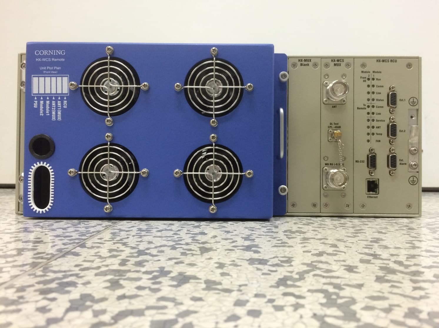
Click to zoom
Application Details
- Equipment Class
- B2I - Part 20 Industrial Booster (CMRS)
- Date of Grant
- Nov 17, 2015
- Application Purpose
- Original Equipment
- Date of Application
- Nov 15, 2015
- Equipment Note
- Optical Repeater Basic model name - HX-WCS-SISO Multi model name - HX-WCS-SISO-PLUS, HX-WCS-SISO-NU
- Frequency Range
- 2350.00000000 - 2360.00000000
- Country
- United States
Documents & Files
Document Text
Text extracted from the exhibit documents filed with the FCC. Open a document above to read the original.
Users Manual
UM_MobileAccessHX WCS Corning Mid-Power HX WCS DAS System User Manual Warranties CMA-318-AEN Page 2 UM_MobileAccessHX WCS Warranties Hardware Corning Optical Communications Wireless, Inc. (“Corning”) warrants to the original purchaser (“Customer”) that for the duration of the warranty period, one (1) year, commencing on the date of shipment of the Hardware, unless otherwise agreed in writing by Corning (the “Hardware Warranty Period”), the Hardware furnished by Corning shall be free in all material respects from defects in material and workmanship, and shall conform to the applicable portions of the Specifications, as defined below (the “Hardware Warranty”). If notified by Customer of any such defects in material or workmanship or nonconformity with applicable portions of the Specifications within the Hardware Warranty Period, Corning shall promptly, at its own election and expense, repair or replace any such Hardware proven to be defective under the terms of this Hardware Warranty. Such repair or replacement shall be Customer’s sole remedy and Corning’s’ sole obligation in the event this Hardware Warranty is invoked. If any components comprising a part of the Hardware are replaced or repaired during the Hardware Warranty Period, the Hardware Warranty Period for such repaired or replaced components shall extend to the longer of (i) the balance of the Hardware Warranty Period or (ii) three (3) months from the date of repair or replacement. For purposes of this Warranty, “Specifications” shall mean the specifications and performance standards of the Products as set forth in documents published by Corning Corning and delivered to Customer which contain technical specifications or performance standards for the Products. If Customer invokes this Hardware Warranty, it shall notify Corning promptly of the claimed defect. Customer will allow Corning to inspect the Hardware at Customer’s location, or to return the Hardware to Corning’ closest repair facility. For Hardware returned to Corning’s’ repair facility, Customer shall be responsible for payment of all transportation and freight costs (including insurance) to Corning’s’ repair facility, and Corning shall be responsible for all transportation and freight costs (including insurance) incurred in connection with the shipment of such Hardware to other repair facilities of Corning and/or its return to Customer. Notwithstanding the foregoing, in no event will Corning be liable for damage to Products resulting from improper handling during or after shipment, misuse, neglect, improper installation, operation or repair (other than by authorized Corning personnel), alteration, accident, or for any other cause not attributable to defects in materials or workmanship on the part of Corning. Corning shall not reimburse or make any allowance to Customer for any labor charges incurred by Customer for replacement or repair of any goods unless such charges are authorized in advance in writing by Corning. Software Warranty Corning warrants to the original purchaser (“Customer”) that for the duration of the warranty period, one (1) year, commencing on the date of shipment of the Software, unless otherwise agreed in writing by Corning (the “Software Warranty Period”), the Software shall conform with, and perform the functions set forth in the Specifications, and shall be free from defects in material or workmanship (the “Software Warranty”). In the event the Software is proven to be defective under the terms of this Software Warranty, Corning shall correct such defects or failure and ensure that the Software conforms with, and performs the functions set forth in, the Specifications. Customer will allow Corning to inspect the Software at Customer’s location or to return it to Corning’s closest repair facility. Notwithstanding the foregoing, Corning shall have no obligation under the Software Warranty if the Warranties P/N 709C015102 Page 3 Software is modified or used with hardware or software not supplied or approved by Corning or if the Software is subject to abuse, improper installation or application, accident, electrical or environmental over-stress, negligence in use, storage, transportation or handling. Third-party software distributed with the Software may carry certain warranties which, to the maximum extent allowed by law, Corning hereby assigns, transfers and otherwise conveys to Customer, provided, however, that Corning itself provides no warranty of any kind, express, implied, statutory or otherwise, for any third-party software provided hereunder. Corning does not warrant any hardware, software or services not provided by Corning. THIS WARRANTY IS THE ONLY WARRANTY MADE BY CORNING AND IS IN LIEU OF ALL OTHER WARRANTIES, EXPRESS OR IMPLIED INCLUDING, BUT NOT LIMITED TO, THE IMPLIED WARRANTIES OF MERCHANTABILITY AND FITNESS FOR A PARTICULAR PURPOSE. CORNING S SHALL NOT BE LIABLE FOR ANY OTHER DAMAGE INCLUDING, BUT NOT LIMITED TO, INDIRECT, SPECIAL OR CONSEQUENTIAL DAMAGES ARISING OUT OF OR IN CONNECTION WITH FURNISHING OF GOODS, PARTS AND SERVICE HEREUNDER, OR THE PERFORMANCE, USE OF, OR INABILITY TO USE THE GOODS, PARTS AND SERVICE. CORNING SALES AGENTS OR REPRESENTATIVES ARE NOT AUTHORIZED TO MAKE COMMITMENTS ON WARRANTY RETURNS. Returns In the event that it is necessary to return any product against above warranty, the following procedure shall be followed: 1. Return authorization is to be received from Corning prior to returning any unit. Advise Corning of the model, Serial number, and discrepancy. The unit may then be forwarded to Corning, transportation prepaid. Devices returned collect or without authorization may not be accepted. 2. Prior to repair, Corning will advise the customer of our test results and any charges for repairing customer- caused problems or out-of-warranty conditions etc. 3. Repaired products are warranted for the balance of the ori ginal warranty period, or at least 90 days from date of shipment. Limitations of Liabilities…
Text truncated - open the document above for the full version.
Cover Letter(s)
© 2015 Corning Incorporated. All Rights Reserved. Date: 09.07.2015 Federal Communications Commission 7435 Oakland Mills Road Columbia MD 21046 c.c. UL Verification Services Inc. (formerly UL CCS) Certification Division 47173 Benicia Street Fremont, CA 94538, USA To whom it may concern: I, the undersigned, hereby authorize Mr. Hyun soo Lee/ RAPA to act on our behalf in all manners relating to application for equipment authorization, including signing of all documents relating to these matters. Any and all acts carried out by Mr. Hyun soo Lee / RAPA on our behalf shall have the same effect as acts of our own. I, the undersigned, hereby certify that we are not subject to a denial of federal benefits, that includes FCC benefits, pursuant to Section 5301 of the Anti-Drug Abuse Act of 1988, 21 U.S.C. 853(a). In authorizing UL Korea as our agent, we still recognize that we are responsible to: a) comply with the relevant provisions of the certification program; b) make all necessary arrangements for the conduct of the evaluation, including provision for examining documentation and access to all areas, records (including internal audit reports) and personnel for the purposes of evaluation (e.g. testing, inspection, assessment, surveillance, reassessment) and resolution of complaints; c) make claims regarding certification only in respect of the scope for which certification has been granted; d) do not use our product certification in such a manner as to bring the Certification Division into disrepute and not make any statement regarding our product certification which the Certification Division may consider misleading or unauthorized; e) upon suspension or cancellation of certification, discontinue use of all advertising matter that contains any reference thereto and return any certification documents as required by the Certification Division; © 2015 Corning Incorporated. All Rights Reserved. f) use certification only to indicate the products are certified as being in conformity with specified standards; g) endeavor to ensure that no certificate or report nor any part thereof is used in a misleading manner; h) ensure that any reference to our product certification in communication media such as documents, brochures or advertising, complies with the requirements of the Certification Division; i) keep a record of all complaints made known to the us relating to the product’s compliance with requirements of the relevant standard and to make these records available to the Certification Division when requested; j) take appropriate action with respect to such complaints and any deficiencies found in products or services that affect compliance with the requirements for certification; k) document the actions taken. This authorization is valid until further written notice from the applicant. Sincerely Yours, Sincerely Yours, Habib Riazi Director, PLM REMARK: 1. This authorization letter will be sent along with your application when filing with the Certification Division. 2. Please follow the format and type it on company letterhead and send original to us. 3. Authorized signature must be in agreement with grantee code contact in FCC database.
Cover Letter(s)
© 2015 Corning Incorporated. All Rights Reserved. Corning Optical Communication Wireless 13221 Woodland Park Rd, Suite 400, Herndon, VA, 20171, USA [email protected] Federal Communications Commission 7435 Oakland Mills Road Columbia MD 21046 Subject: Request for Confidentiality FCC ID: OJFHX-WCS-SISO To Whom It May Concern: Pursuant to the provisions of Sections 0.457 and 0.459 of the Commission’s rules (47 CFR §§ 0.457, 0.459), we are requesting the Commission to withhold the following attachments as confidential document from public disclosure indefinitely. 1. Block Diagram 2. Schematic Diagram 3. Operational Description 4. Layout 5. Tune-up Procedure Above mentioned document contains detailed system and equipment description are considered as proprietary information in operation of the equipment. The public disclosure of above documents might be harmful to our company and would give competitor an unfair advantage in the market. It is our understanding that all measurement test reports, FCC ID label format and correspondent during certification review process cannot be granted as confidential documents and those information will be available for public review once the grant of equipment authorization is issued. Sincerely Yours, Habib Riazi Director, PLM
External Photos
Corning Optical Communications Wireless, Inc. FCCID : HX-WCS-SISO MODEL:HX-WCS-SISO-NU It should not be reproduced in full or partly without the written approval by TCL of RAPA. Testing and Certification Laboratory Appendix 3. External Photos of EUT 1. Top Corning Optical Communications Wireless, Inc. FCCID : HX-WCS-SISO MODEL:HX-WCS-SISO-NU It should not be reproduced in full or partly without the written approval by TCL of RAPA. Testing and Certification Laboratory Appendix 3. External Photos of EUT 2. Bottom Corning Optical Communications Wireless, Inc. FCCID : HX-WCS-SISO MODEL:HX-WCS-SISO-NU It should not be reproduced in full or partly without the written approval by TCL of RAPA. Testing and Certification Laboratory Appendix 3. External Photos of EUT 3. Front1 Corning Optical Communications Wireless, Inc. FCCID : HX-WCS-SISO MODEL:HX-WCS-SISO-NU It should not be reproduced in full or partly without the written approval by TCL of RAPA. Testing and Certification Laboratory Appendix 3. External Photos of EUT 4. Front2 Corning Optical Communications Wireless, Inc. FCCID : HX-WCS-SISO MODEL:HX-WCS-SISO-NU It should not be reproduced in full or partly without the written approval by TCL of RAPA. Testing and Certification Laboratory Appendix 3. External Photos of EUT 5. Back1 Corning Optical Communications Wireless, Inc. FCCID : HX-WCS-SISO MODEL:HX-WCS-SISO-NU It should not be reproduced in full or partly without the written approval by TCL of RAPA. Testing and Certification Laboratory Appendix 3. External Photos of EUT 6. Right Corning Optical Communications Wireless, Inc. FCCID : HX-WCS-SISO MODEL:HX-WCS-SISO-NU It should not be reproduced in full or partly without the written approval by TCL of RAPA. Testing and Certification Laboratory Appendix 3. External Photos of EUT 7. Left
External Photos
Corning Optical Communications Wireless, Inc. FCCID : HX-WCS-SISO MODEL:HX-WCS-SISO-PLUS It should not be reproduced in full or partly without the written approval by TCL of RAPA. Testing and Certification Laboratory Appendix 3. External Photos of EUT 1. Top Corning Optical Communications Wireless, Inc. FCCID : HX-WCS-SISO MODEL:HX-WCS-SISO-PLUS It should not be reproduced in full or partly without the written approval by TCL of RAPA. Testing and Certification Laboratory Appendix 3. External Photos of EUT 2. Bottom Corning Optical Communications Wireless, Inc. FCCID : HX-WCS-SISO MODEL:HX-WCS-SISO-PLUS It should not be reproduced in full or partly without the written approval by TCL of RAPA. Testing and Certification Laboratory Appendix 3. External Photos of EUT 3. Front1 Corning Optical Communications Wireless, Inc. FCCID : HX-WCS-SISO MODEL:HX-WCS-SISO-PLUS It should not be reproduced in full or partly without the written approval by TCL of RAPA. Testing and Certification Laboratory Appendix 3. External Photos of EUT 4. Front2 Corning Optical Communications Wireless, Inc. FCCID : HX-WCS-SISO MODEL:HX-WCS-SISO-PLUS It should not be reproduced in full or partly without the written approval by TCL of RAPA. Testing and Certification Laboratory Appendix 3. External Photos of EUT 5. Back1 Corning Optical Communications Wireless, Inc. FCCID : HX-WCS-SISO MODEL:HX-WCS-SISO-PLUS It should not be reproduced in full or partly without the written approval by TCL of RAPA. Testing and Certification Laboratory Appendix 3. External Photos of EUT 6. Right Corning Optical Communications Wireless, Inc. FCCID : HX-WCS-SISO MODEL:HX-WCS-SISO-PLUS It should not be reproduced in full or partly without the written approval by TCL of RAPA. Testing and Certification Laboratory Appendix 3. External Photos of EUT 7. Left
Internal Photos
Corning Optical Communications Wireless, Inc. FCCID : HX-WCS-SISO It should not be reproduced in full or partly without the written approval by TCL of RAPA. Testing and Certification Laboratory Appendix 4. Internal Photos of EUT <Optic Module> 1. Top of Internal PCB1 2. Bottom of Internal PCB1 Corning Optical Communications Wireless, Inc. FCCID : HX-WCS-SISO It should not be reproduced in full or partly without the written approval by TCL of RAPA. Testing and Certification Laboratory 3. Top of Internal Optic PCB2 4. Bottom of Internal PCB2 Corning Optical Communications Wireless, Inc. FCCID : HX-WCS-SISO It should not be reproduced in full or partly without the written approval by TCL of RAPA. Testing and Certification Laboratory Appendix 4. Internal Photos of EUT <PSU> 1. Top of Internal PCB1 2. Bottom of Internal PCB1 Corning Optical Communications Wireless, Inc. FCCID : HX-WCS-SISO It should not be reproduced in full or partly without the written approval by TCL of RAPA. Testing and Certification Laboratory 3. Top of Internal PCB2 4. Bottom of Internal PCB2 Corning Optical Communications Wireless, Inc. FCCID : HX-WCS-SISO It should not be reproduced in full or partly without the written approval by TCL of RAPA. Testing and Certification Laboratory 5. Top of Internal PCB3 6. Bottom of Internal PCB3 Corning Optical Communications Wireless, Inc. FCCID : HX-WCS-SISO It should not be reproduced in full or partly without the written approval by TCL of RAPA. Testing and Certification Laboratory 7. Top of Internal PCB4 8. Bottom of Internal PCB4 Corning Optical Communications Wireless, Inc. FCCID : HX-WCS-SISO It should not be reproduced in full or partly without the written approval by TCL of RAPA. Testing and Certification Laboratory Appendix 4. Internal Photos of EUT <AMP> 1. Top of Internal PCB Corning Optical Communications Wireless, Inc. FCCID : HX-WCS-SISO It should not be reproduced in full or partly without the written approval by TCL of RAPA. Testing and Certification Laboratory 2. Bottom of Internal PCB Corning Optical Communications Wireless, Inc. FCCID : HX-WCS-SISO It should not be reproduced in full or partly without the written approval by TCL of RAPA. Testing and Certification Laboratory Appendix 4. Internal Photos of EUT <RCU> 1. Top of Internal PCB1 2. Bottom of Internal PCB1 Corning Optical Communications Wireless, Inc. FCCID : HX-WCS-SISO It should not be reproduced in full or partly without the written approval by TCL of RAPA. Testing and Certification Laboratory 3. Top of Internal PCB2 4. Bottom of Internal PCB2 Corning Optical Communications Wireless, Inc. FCCID : HX-WCS-SISO It should not be reproduced in full or partly without the written approval by TCL of RAPA. Testing and Certification Laboratory 5. Top of Internal PCB3 6. Bottom of Internal PCB3
Test Report
Page : 1 / 127 Report No. : RAPA15-O-036 It should not be reproduced in full or partly without the written approval by TCL of RAPA. FCC CFR Part 27(Ver4.0) Testing and Certification Laboratory TEST REPORT Report number RAPA15-O-036 Applicant Name Corning Optical Communications Wireless Inc. Logo Address 13221 Woodland Park Rd, Suite 400 Herndon, Virginia 20171 USA Manufacturer Name Corning Optical Communications Wireless Inc. Address 13221 Woodland Park Rd, Suite 400 Herndon, Virginia 20171 USA Type of equipment Optical Repeater Basic model name HX-WCS-SISO Multi model name HX-WCS-SISO-PLUS, HX-WCS-SISO-NU Serial number N/A FCC ID OJFHX-WCS-SISO Test duration June 19, 2015 to October 12, 2015 Date of issue October 12, 2015 Total page 127 pages (including this page) SUMMARY The equipment complies with the requirements of FCC CFR 47 Part 27 Subpart C. This test report only contains the result of a single test of the sample supplied for the examination. It is not a general valid assessment of the features of the respective products of the mass-production. October 12, 2015 October 12, 2015 Tested by Hyun Soo Lee Reviewed by Sukil Park Manager Executive Managing Director Page : 2 / 127 Report No. : RAPA15-O-036 It should not be reproduced in full or partly without the written approval by TCL of RAPA. FCC CFR Part 27(Ver4.0) Testing and Certification Laboratory Test Report Version History Version Date Revised by Reason for revision 1.0 September 16, 2015 Hyun Soo Lee Original Document 2.0 October 01, 2015 Hyun Soo Lee Revision - Measurement Uncertain - Test procedure 3.0 October 07, 2015 Hyun Soo Lee Measurement data insertion and revision - PAPR - Out of band rejection - Spurious emission 4.0 October 12, 2015 Hyun Soo Lee Update measurement and test plots - Output power test procedure - Spurious emission Page : 3 / 127 Report No. : RAPA15-O-036 It should not be reproduced in full or partly without the written approval by TCL of RAPA. FCC CFR Part 27(Ver4.0) Testing and Certification Laboratory CONTENTS 1. General description of EUT .............................................................................................................................. 4 1.1 Applicant ......................................................................................................................................................... 4 1.2 Manufacturer .................................................................................................................................................. 4 1.3 Basic description of EUT ................................................................................................................................ 4 1.4 Alternative type(s)/model(s) ........................................................................................................................... 4 1.5 Electrical specification .................................................................................................................................... 5 2. General information of test ............................................................................................................................. 11 2.1 Test standards and results ........................................................................................................................... 11 2.2 Description of EUT modification ................................................................................................................... 11 2.3 Test configuration ......................................................................................................................................... 11 2.4 Test setup ..................................................................................................................................................... 12 2.5 Measurement Uncertainty ............................................................................................................................ 12 3. Measurement data ........................................................................................................................................... 13 3.1 Occupied Bandwidth / 26 dB Emission Bandwidth .......................................................................................... 13 3.2 Emissions at the band edges ........................................................................................................................ 20 3.3 Conducted spurious emission ........................................................................................................................ 27 3.4 Transmitter Conducted Output power ........................................................................................................... 101 3.5 Radiated spurious emission ....................................................................................................................... 110 3.6 Frequency stability ..................................................................................................................................... 113 3.7 Out of band rejection .................................................................................................................................. 122 4. RF exposure statement ................................................................................................................................. 124 4.1 Friis transmission formula .......................................................................................................................... 124 4.2 Information of Antenna ............................................................................................................................... 125 4.3 Calculation of MPE at 115 cm .................................................................................................................... 126 5. Test equipment list ...............................................................................................................................…
Text truncated - open the document above for the full version.
Test Report
Page : 101 / 127 Report No. : RAPA15-O-036 It should not be reproduced in full or partly without the written approval by TCL of RAPA. FCC CFR Part 27(Ver4.0) Testing and Certification Laboratory 3.4 Transmitter Conducted Output power 3.4.1 Specification • FCC Part 2.1046 • FCC Part 27.50 (a)(1)(i) 3.4.2 Test Description The method used is as detailed in FCC KDB 971168 The measurement were performed in max output power transmitting mode at all channel of the 2350 MHz ~ 2360 MHz frequency ranges. Peak Power Output not exceed 2000W(63dBm) The EUT output power was connected to the spectrum analyzer through appropriate attenuator. The output power was measured using a spectrum analyzer CHANNEL POWER function. The peak-to-average power ratio (PAPR) of the transmitter output power must not exceed 13 dB Transmitter Conducted Output power was measured under the three types of modulation mode which are QPSK, 16QAM and 64QAM, and resource block was 50. 3.4.3 Test Procedure The test procedure used is as detailed in FCC KDB 935210 D05 V01 3.5.2 e) The EUT antenna terminal was connected to the spectrum analyzer through an external attenuator and an appropriate coaxial cable. The EUT RF output was modulated. Special attention was taken to prevent spectrum analyzer RF input overload. 3.4.4 Test equipment list Equipment Model Name Manufacturer EUT HX-WCS-SISO Corning Optical Communications Wireless Inc. MHU HX-WCS-MHU Corning Optical Communications Wireless Inc. Signal Generator N5182A Agilent Spectrum Analyzer N9020A Agilent Attenuator PE7019-20 Pasternack DC Power Supply 6674A Agilent 3.4.5 Test condition • Test place: Shield room • Test environment: 22.5 °C, 44 % R.H. Page : 102 / 127 Report No. : RAPA15-O-036 It should not be reproduced in full or partly without the written approval by TCL of RAPA. FCC CFR Part 27(Ver4.0) Testing and Certification Laboratory 3.4.6 Test results • Port1 WCS Block Bandwidth [MHz] Frequency [MHz] Modulation Conducted Output Level [dBm] EIRP [dBm] A+B 10 2 355.0 QPSK 33.10 48.10 16QAM 32.98 47.99 64QAM 33.06 48.06 A 5 2 352.5 QPSK 33.06 48.06 16QAM 32.98 47.98 64QAM 32.97 47.97 B 5 2 357.5 QPSK 32.99 47.99 16QAM 32.98 47.98 64QAM 33.01 48.01 • Port1 - PAPR WCS Block Bandwidth [MHz] Frequency [MHz] Modulation Average Power Level [dBm] PAPR [dB] A+B 10 2 355.0 QPSK 32.95 10.33 16QAM 32.98 10.26 64QAM 32.93 10.43 A 5 2 352.5 QPSK 32.97 10.05 16QAM 32.97 10.28 64QAM 32.97 10.19 B 5 2 357.5 QPSK 32.99 9.92 16QAM 33.00 10.13 64QAM 33.00 10.18 Page : 103 / 127 Report No. : RAPA15-O-036 It should not be reproduced in full or partly without the written approval by TCL of RAPA. FCC CFR Part 27(Ver4.0) Testing and Certification Laboratory 3.4.7 Test Plots • Port1 / LTE 10 MHz / 2 355 MHz / QPSK • Port1 / LTE 10 MHz / 2 355 MHz / 16QAM Page : 104 / 127 Report No. : RAPA15-O-036 It should not be reproduced in full or partly without the written approval by TCL of RAPA. FCC CFR Part 27(Ver4.0) Testing and Certification Laboratory • Port1 / LTE 10 MHz / 2 355 MHz / 64QAM • Port1 / LTE 5 MHz / 2 352.5 MHz / QPSK Page : 105 / 127 Report No. : RAPA15-O-036 It should not be reproduced in full or partly without the written approval by TCL of RAPA. FCC CFR Part 27(Ver4.0) Testing and Certification Laboratory • Port1 / LTE 5 MHz / 2 352.5 MHz / 16QAM • Port1 / LTE 5 MHz / 2 352.5 MHz / 64QAM Page : 106 / 127 Report No. : RAPA15-O-036 It should not be reproduced in full or partly without the written approval by TCL of RAPA. FCC CFR Part 27(Ver4.0) Testing and Certification Laboratory • Port1 / LTE 5 MHz / 2 357.5 MHz / QPSK • Port1 / LTE 5 MHz / 2 357.5 MHz / 16QAM Page : 107 / 127 Report No. : RAPA15-O-036 It should not be reproduced in full or partly without the written approval by TCL of RAPA. FCC CFR Part 27(Ver4.0) Testing and Certification Laboratory • Port1 / LTE 5 MHz / 2 357.5 MHz / 64QAM Page : 108 / 127 Report No. : RAPA15-O-036 It should not be reproduced in full or partly without the written approval by TCL of RAPA. FCC CFR Part 27(Ver4.0) Testing and Certification Laboratory 3.4.8 PAPR Test Plots • Port1 / LTE 5 MHz / 2 352.5 MHz / 64QAM • Port1 / LTE 5 MHz / 2 357.5 MHz / 64QAM Page : 109 / 127 Report No. : RAPA15-O-036 It should not be reproduced in full or partly without the written approval by TCL of RAPA. FCC CFR Part 27(Ver4.0) Testing and Certification Laboratory • Port1 / LTE 10 MHz / 2 355 MHz / 64QAM Page : 110 / 127 Report No. : RAPA15-O-036 It should not be reproduced in full or partly without the written approval by TCL of RAPA. FCC CFR Part 27(Ver4.0) Testing and Certification Laboratory 3.5 Radiated spurious emission 3.5.1 Specification • FCC Part 2.1053 • FCC Part 27.53 3.5.2 Test Description The highest gain antenna to be used with the EUT was tested for final measurements. The EUT was configured for the lowest and the highest transmit frequency. For each configuration, the spectrum was scanned throughout the specified range. While scanning, emissions from the EUT were maximized by rotating the EUT on a turntable, adjusting the position of the EUT and EUT antenna in three orthogonal axis, and adjusting the measurement antenna height and polarization (per ANSI C63. 10:2009). A preamp and high pass filter were used for this test in order to provide sufficient measured sensitivity. For licensed transmitters, the FCC reference TIA/EIA-603 as the measurement procedure standard. TIA/EIA- 603 Section 2.2.12 describes a method for measuring radiated spurious emission that utilizes an antenna substitution method: At an approved test site, the transmitter is place on a remotely controlled turntable, and the measurement antenna is place 3 meters from the transmitter. The transmitter is place on a remotely controlled turntable, and the measurement antenna is placed 3 meters from the transmitter. The turntable azimuth is varied to maximize the level of spurious emissions. The height of the measurement antenna is also varied from 1 to 4 meters. The amplitude and frequency of the…
Text truncated - open the document above for the full version.
Test Setup Photos
Corning Optical Communications Wireless, Inc. FCCID : HX-WCS-SISO MODEL: H X-WCS-SISO-PLUS It should not be reproduced in full or partly without the written approval by TCL of RAPA. Testing and Certification Laboratory Appendix 1. Photos of Test Setup 1. Test Setup of Radiation Corning Optical Communications Wireless, Inc. FCCID : HX-WCS-SISO MODEL: H X-WCS-SISO-PLUS It should not be reproduced in full or partly without the written approval by TCL of RAPA. Testing and Certification Laboratory Appendix 1. Photos of Test Setup 1. Test Setup of conducted emission from antenna port tests Corning Optical Communications Wireless, Inc. FCCID : HX-WCS-SISO MODEL: H X-WCS-SISO-PLUS It should not be reproduced in full or partly without the written approval by TCL of RAPA. Testing and Certification Laboratory
Contact Information
Applicant
Dana Whitney(Director of Operations and Program)
Test Firm
TCL of RAPAWoong Gul Kang
[email protected]82-31-427-9100
Technical Specifications
| # | Rule Parts | Frequency Range | Power Output | Emission | Tolerance |
|---|---|---|---|---|---|
| 4 | 27 | 2.35 GHz - 2.36 GHz | 2.023 W | 8M97W7D | Amp |
Other Applications from Corning Optical Communication LLC

OJFE62-N3-7US
Aug 29, 2024Remote Unit, Radio Node
Equipment Class
B2I - Part 20 Industrial Booster (CMRS)
OJFDHRU-G2-19
Apr 09, 2024HRU Digital High Power Amplifier Module supporting PCS
Equipment Class
B2I - Part 20 Industrial Booster (CMRS)
OJFDLRUG2678
Oct 17, 2023Low Band dRAU
Equipment Class
B2I - Part 20 Industrial Booster (CMRS)
OJFDMRUG22325
Jul 31, 2023digital Medium-power Remote Unit
Equipment Class
B2I - Part 20 Industrial Booster (CMRS)
OJFDMRUG2678
Jul 30, 2023digital Medium-power Remote Unit
Equipment Class
B2I - Part 20 Industrial Booster (CMRS)